Enel X JuicePedestal User manual

JuicePedestal
User Manual
ENGLISH


4
Installation Area
Refer to the Enel X Way Site Design Guide.
Installation
Each JuiceBox must be on its own circuit. Refer to the Wiring Design section of the Enel X
Way Site Design Guide for additional information.
1. Turn o the mains power to the hardwire connections.
2. Use a multimeter to ensure that there is no power at the hardwire connections.
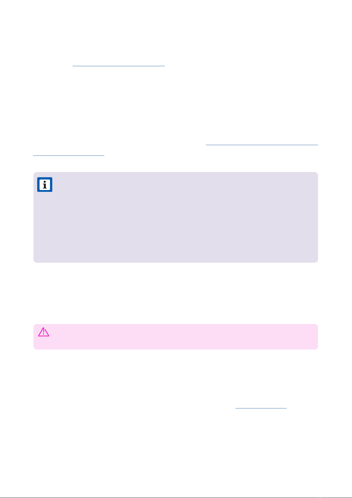
3. Route the mains power hardwire connection into the pedestal from the boom, then
position the pedestal onto the ground stud anchors.
4. Secure the pedestal to the ground stud anchors (refer to Installation Area for more
information).
NOTE:
>The JuicePedestal must be installed in accordance with the National Electrical
Code (NFPA 70) and all applicable local jurisdiction requirements.
>Junction Boxes must be UL Listed or UL Ceied for outdoor-use due to local
regulations, if necessary.
>Conduit ings must be liquid-tight and UL Listed or UL Ceied for outdoor-
use.
WARNING: Do not continue with the installation until the multimeter shows
that there is no power at the hardwire connections to mains.
5
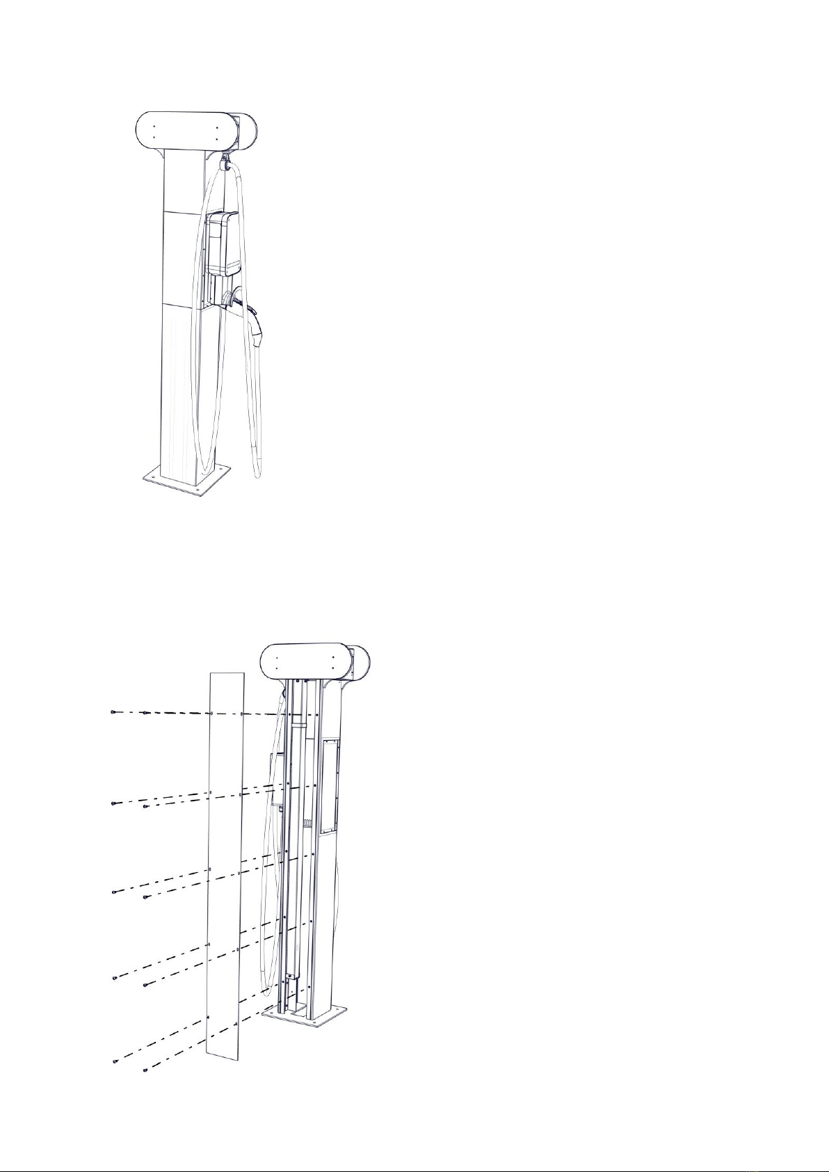
5. Release the 10 fasteners that secure the back plate to the pedestal. Remove the back
plate.

6
6. For each JuiceBox, install a waterproof junction box to house the connection.
7. Connect the mains power wires to the charging station wires.
8. Reinstall the back plate (refer to step 5).
9. Reconnect power to the hardwire connections. The charging stations turn on
automatically.
BLACK RED GREEN
L1 L2 Ground
NOTE: The JuiceBox ex conduit has a diameter of 1 in.
7
Replace a JuiceBox
This section describes how to replace a JuiceBox which is installed on a JuicePedestal.
NOTE: Do not discard any pas or fasteners unless explicitly instructed to do so.
NOTE: Use a multimeter to ensure that wires supplying power to the pedestal
indicates a zero voltage, as there may be more than one circuit in the junction box.
1. Turn o all the circuit breakers that supply power to the pedestal.
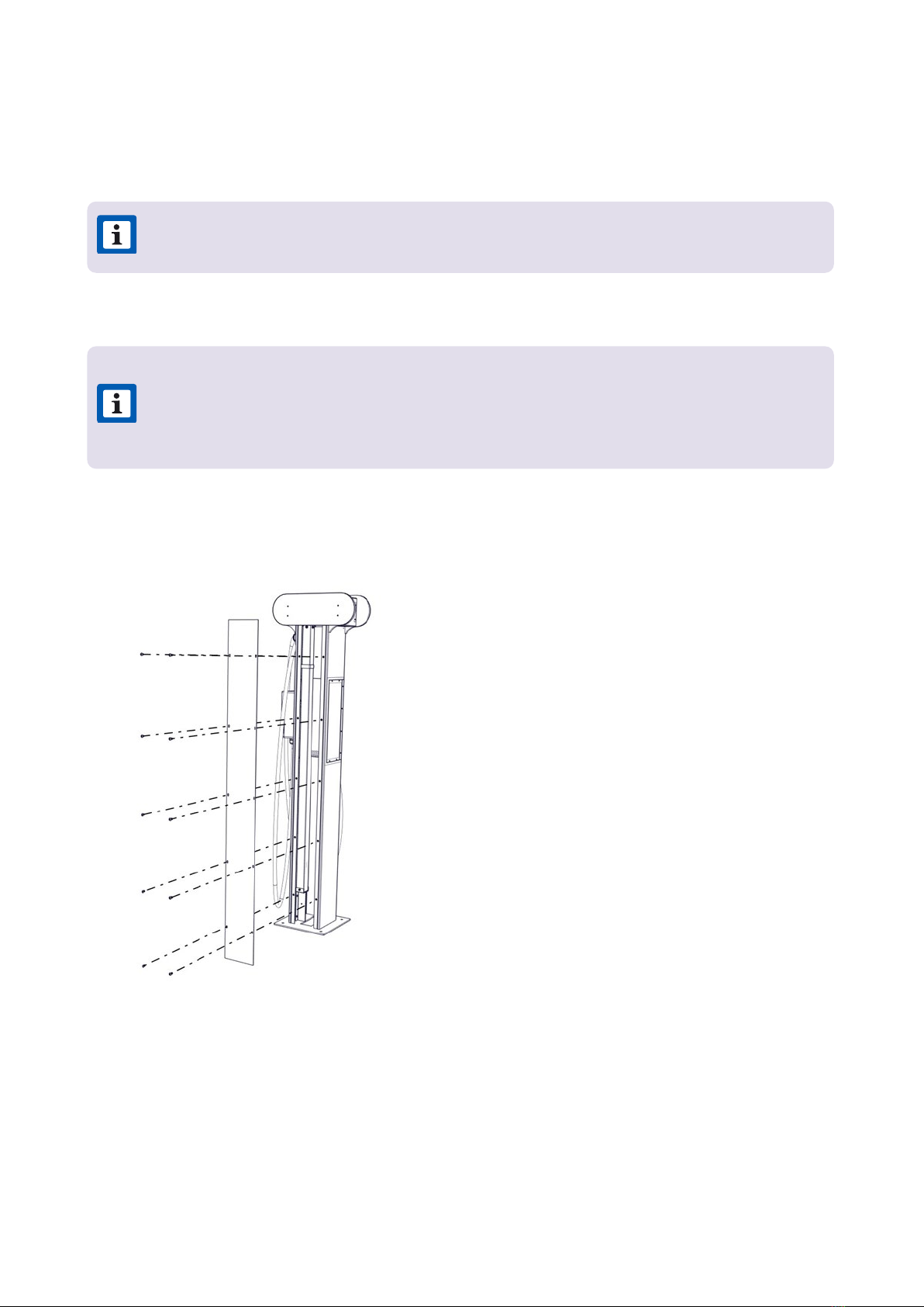
2. Release the 10 fasteners that secure the back plate to the pedestal. Remove the back
plate.
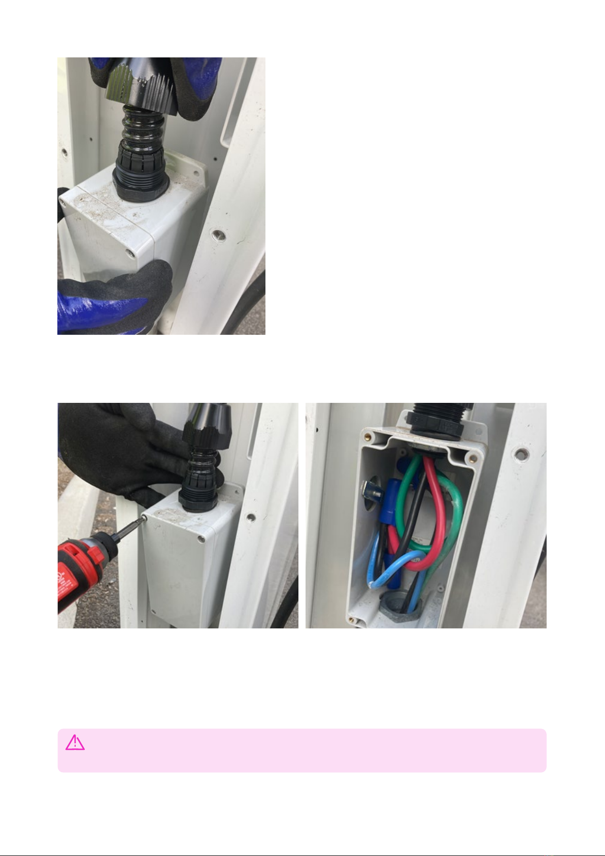
3. To disconnect the electrical connection to the JuiceBox, do the following steps:
a. Remove the cable gland ing that secure the conduit from JuiceBox to the junction
box.
8
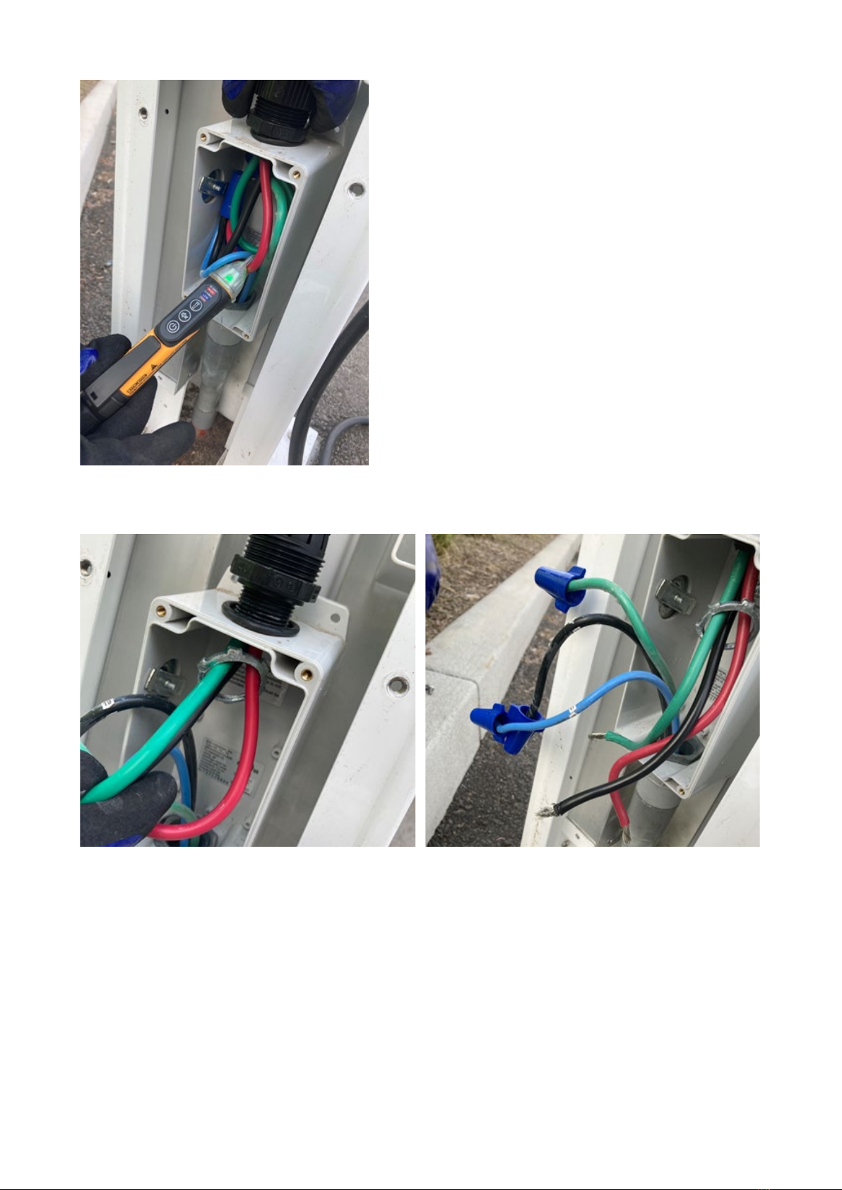
b. Open the junction box within the pedestal and disconnect the connecting means
within the junction box.
c. Use a multimeter to ensure that there is no power at the hardwire connections.
WARNING: Do not continue with this procedure until the multimeter shows
that there is no power at the hardwire connections to mains.
9
d. Disconnect the JuiceBox wiring from the incoming power wiring in the junction box.
4. If the JuiceBox is connected to the UPT, disconnect the Ethernet cable(s) from the back
cover of the payment terminal.

10
5. If the JuiceBox is connected to the JuiceRouter, disconnect the Ethernet cable from the
po on the base of the JuiceRouter.
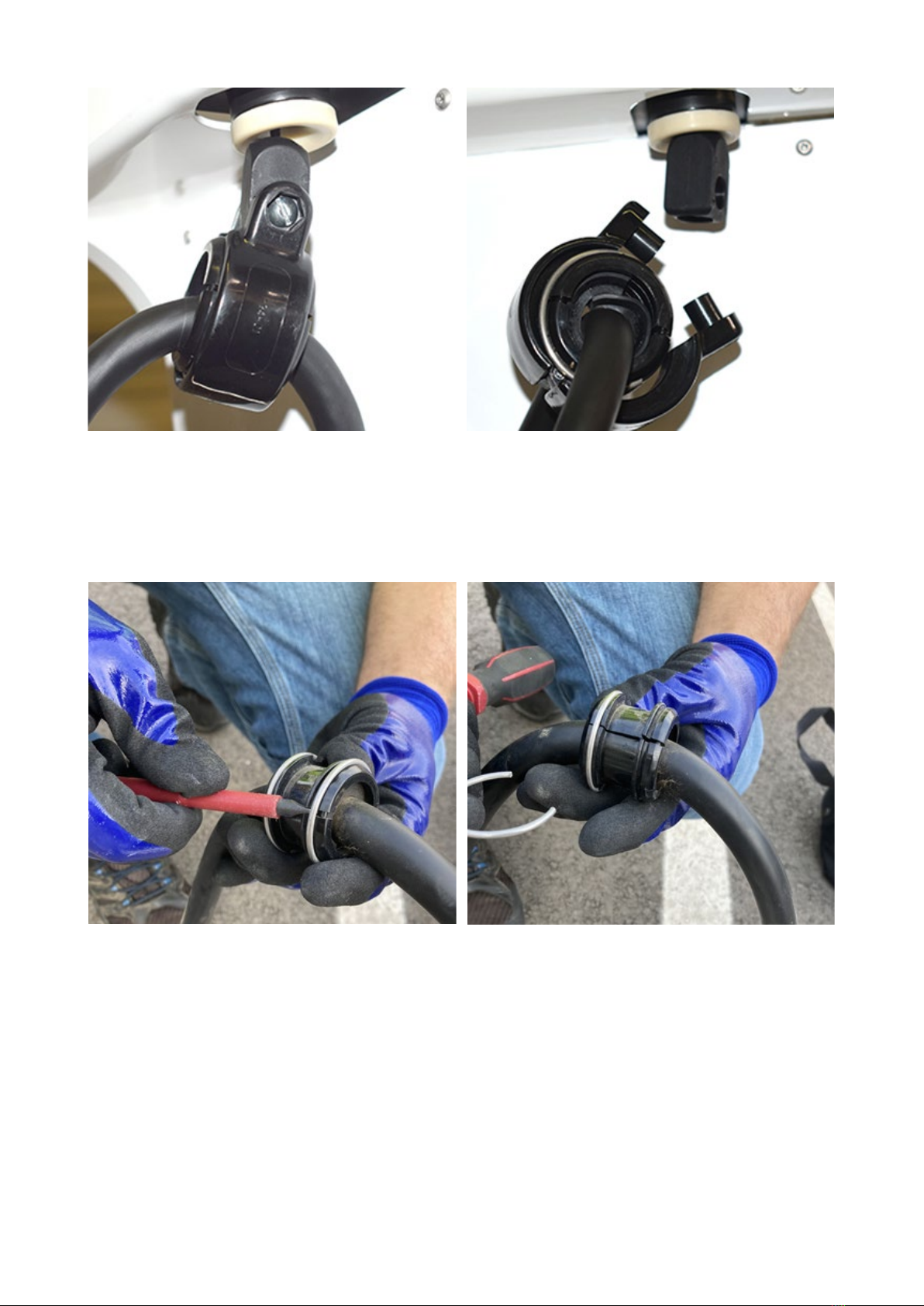
6. Release the screw that secures the cable holder ring, and then release the cable holder
ring from the retractor.
11
7. Use a at head screw driver to remove the locking rings from the cable holder ring.
Remove the cable holder ring from the cable.
8. Release the 2 phillips head screws that secure the JuiceBox to the side panel of the
pedestal.
12
9. Remove the Ethernet cable and conduit gland of old JuiceBox from the holes on the side
panel. Remove the old JuiceBox.
NOTE: Carefully remove the ethernet cable from the hole on the side panel to
avoid any damage to the connector.

13
10. Route the Ethernet cable and the conduit gland of the new JuiceBox into the holes on
the side panel. Position the JuiceBox onto a pedestal (refer to step 9).
11. Reinstall the 2 phillips head screws to secure the JuiceBox to the side panel of the
pedestal (refer to step 8).
12. Add the rubber strip around the cable, position the cable holder ring on the cable and
install the locking rings on the cable holder ring.
13. Install the cable holder ring onto the stopper.

14
14. Connect the Ethernet cable to the po on the base of the JuiceRouter (refer to step 5).
15. Connect the Ethernet cable(s) to the back cover of the payment terminal (refer to step
4).
16. To connect the electrical connection to the JuiceBox, do the following steps:
a. Inse the new JuiceBox wires and conduit into the junction box (refer to step 3d).
b. Connect the JuiceBox wires to the incoming power wiring using the original
connecting means and close the junction box (refer to step 3b).
c. Tighten the cable gland ing that secure the conduit from JuiceBox to the junction
box (refer to step 3a).
17. Reinstall the back plate (refer to step 2).
18. Turn on all the circuit breakers that supply power to the pedestal. The JuiceBox turns
on automatically and the LED indicator ashing to blue color.
15
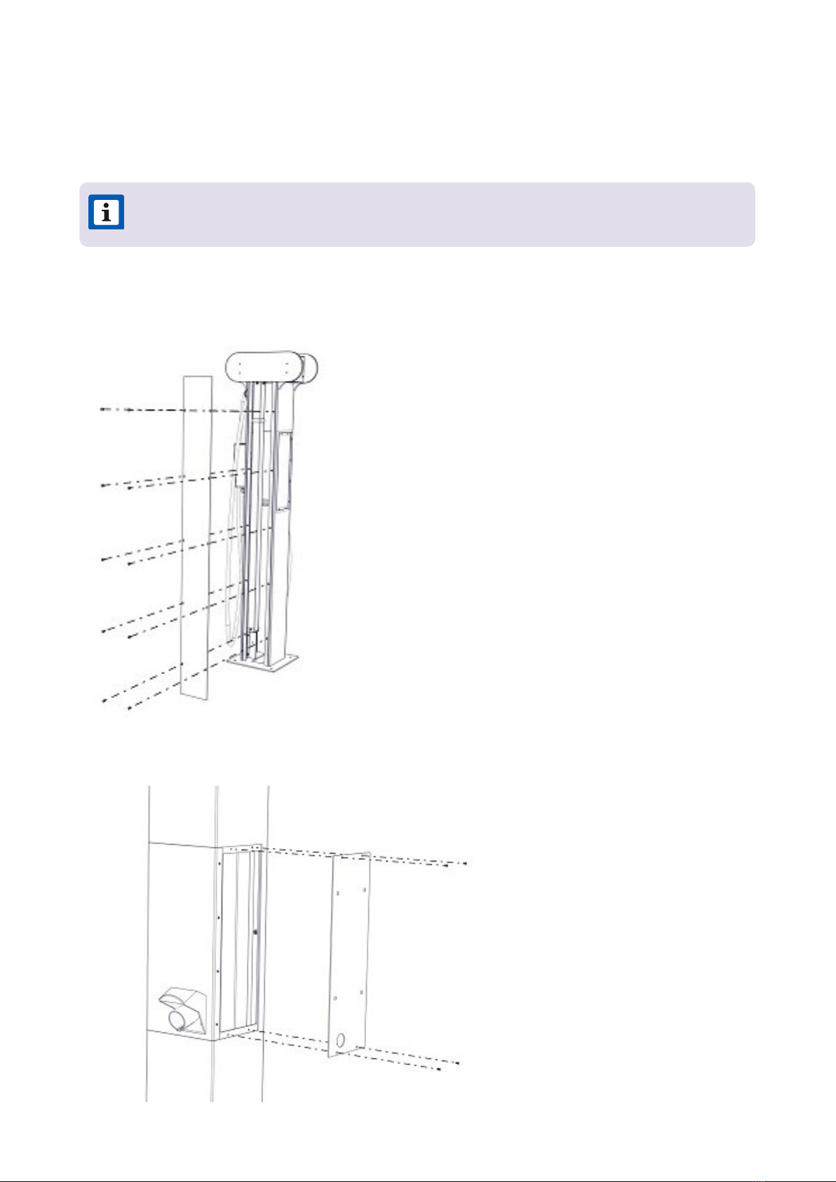
1. Release the 10 fasteners that secure the back plate to the pedestal. Remove the back
plate.
Replace Retractor
This section describes how to replace a retractor.
2. Release the 8 fasteners that secure the frontplate to the pedestal. Remove the frontplate.
NOTE: Do not discard any pas or fasteners unless explicitly instructed to do so.

16
3. Use a T9 Torx Security bit to release the fasteners that secure the top plate.
4. Release the screw that secures the cable holder ring, then release the cable holder ring
from the retractor.
5. Use a at head screw driver to remove the locking rings from the cable holder ring.
Remove the cable holder ring from the cable.

17
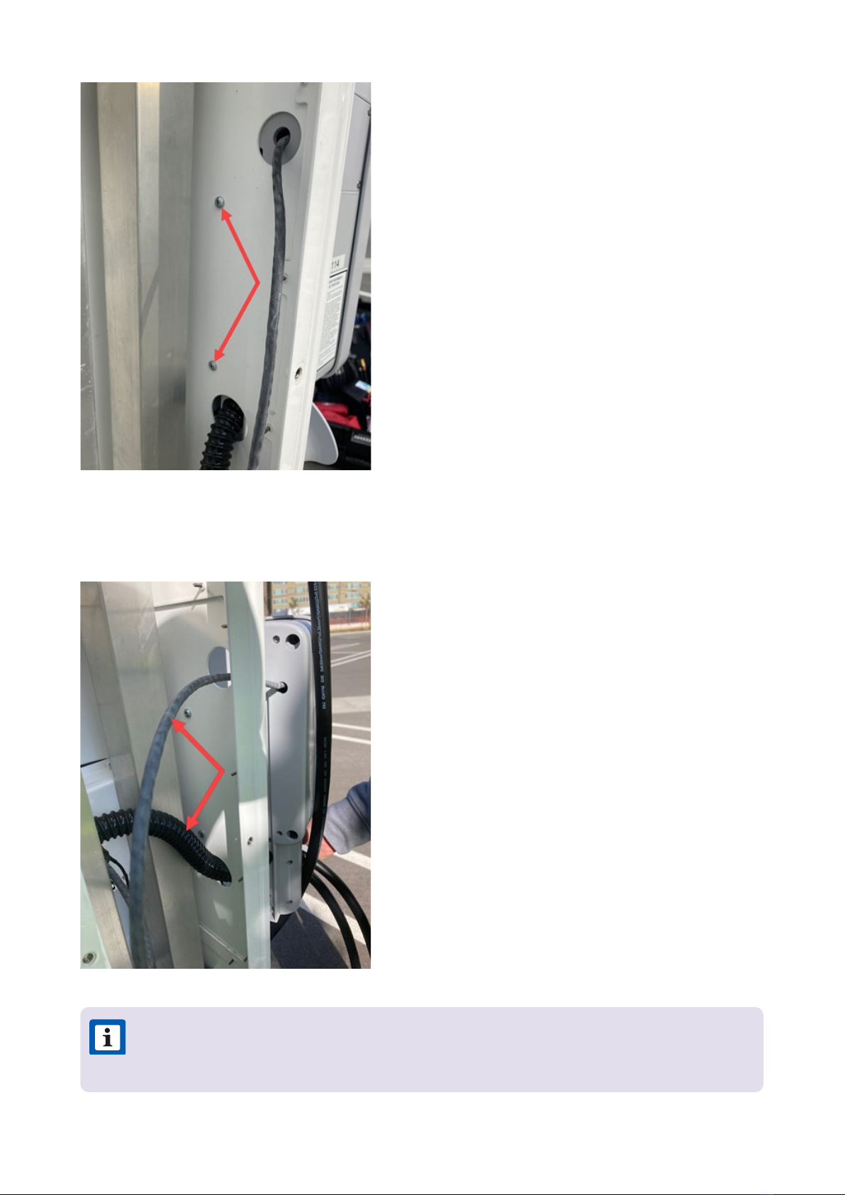
6. While restraining the nut on the opposite side, use a 5/64 in hex key to release the
fastener that secures the upper pole bracket to the pedestal. Remove the upper pole
bracket from the pedestal.
7. Release the fasteners (x4) that secure the lower pole bracket from the pedestal.
NOTE: 2 of the fasteners are not easily visible.
NOTE: Do not remove the lower pole bracket at this time.
18
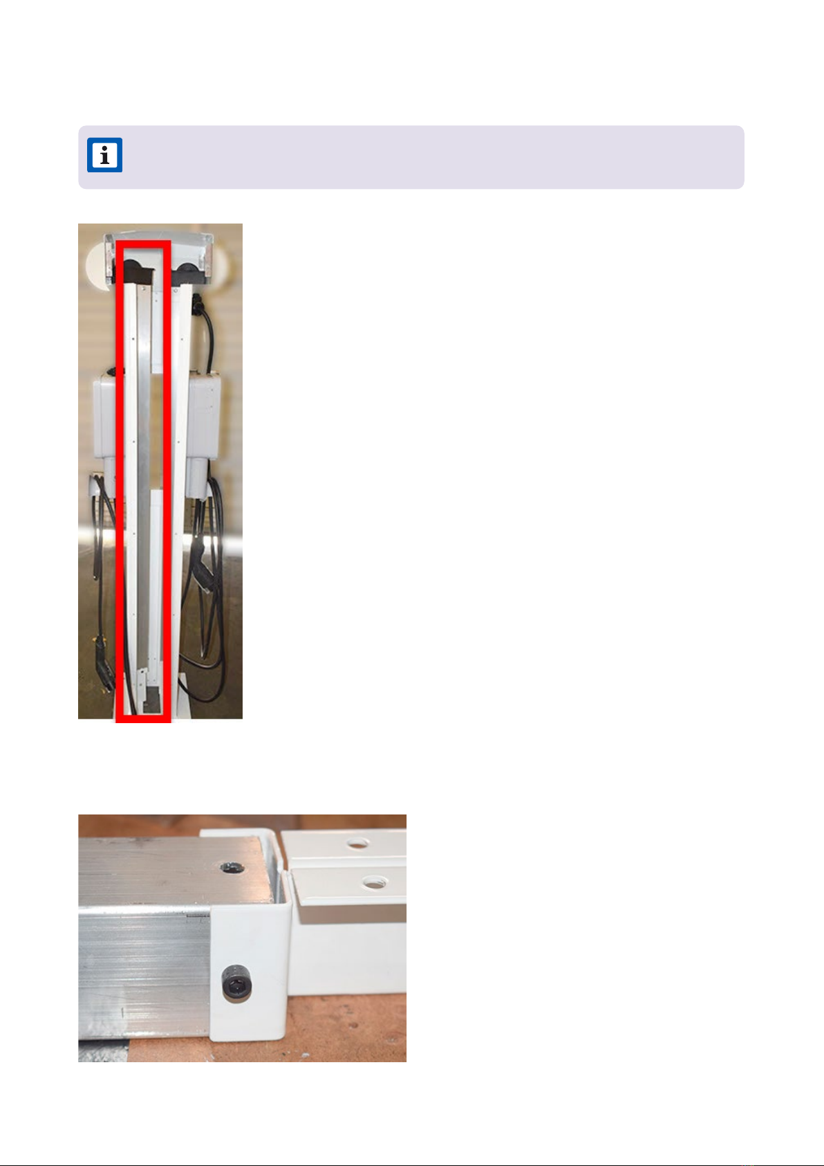
8. Remove the retractor assembly by lifting it upwards, then out of the pedestal.
9. While restraining the nut on the opposite side, use a 3/16 in hex key to release the
fastener that secures the lower pole bracket to the retractor assembly.
NOTE: The bracket from step 7 is removed as pa of the retractor assembly.

19
10. Transfer the lower pole bracket to the new retractor assembly.
11. Position the retractor assembly within the pedestal (refer to step 8).
12. Reinstall the fasteners that secure the lower pole bracket to the pedestal (refer to step
7).
13. Reinstall the fastener that secures the upper pole bracket to the pedestal (refer to step
6).
14. Untie the knot and remove the washer from the retractor cord.
15. Install the stopper:
NOTE: Read this entire step before continuing.
TIP: Push the retractor pole towards the outside of the pedestal to properly install
the fastener.
TIP: Hand tighten the front (visible) fasteners before installing the rear (hidden)
fasteners. When all fasteners are hand-tight, fully tighten the hidden fasteners
rst, then fully tighten the visible fasteners.

20
a. Pull down on the retractor cord until you feel the tension from the counterweight, then
pull the retractor cord out 1 additional inch. Hold the cord in this position.
b. While continuing to hold the cord in place from the previous step, install the stopper
onto the retractor cord. Slide the stopper all the way to the top of the cord.
c. Use a marker to mark the position of the boom of the stopper on the cord. Ensure that
the stopper remains above this mark during the next steps.
d. Pull out the cord and tie a knot at the position that was marked previously.
e. Install the clamshell over the knot.
f. Slide the stopper over the clamshell.
Table of contents
Other Enel X Automobile Accessories manuals


Popular Automobile Accessories manuals by other brands


ULTIMATE SPEED
ULTIMATE SPEED 279746 Assembly and Safety Advice

SSV Works
SSV Works DF-F65 manual

ULTIMATE SPEED
ULTIMATE SPEED CARBON Assembly and Safety Advice

Witter
Witter F174 Fitting instructions

WeatherTech
WeatherTech No-Drill installation instructions

TAUBENREUTHER
TAUBENREUTHER 1-336050 Installation instruction