Enelion Wallbox Adspace User manual

Copyright, Enelion Sp. z o. o.
The manual may change as the product develops. The information provided may not be correct. All rights
reserved.
Revision: V 3.4
Number of pages: 21
Released: August 3, 2021
1

Wallbox Adspace - Assembly manual 8 - 2021
Contents
1 Important information 4
1.1 General Provisions . . . . . . . . . . . . . . . . . . . . . . . . . . . . . . . . . . . . . . . . . . . 4
1.2 Safety instructions . . . . . . . . . . . . . . . . . . . . . . . . . . . . . . . . . . . . . . . . . . . . 4
2 General information 5
2.1 Opening and closing Enelion Wallbox Adspace. . . . . . . . . . . . . . . . . . . . . . . . . . . . . 5
3 Design indications of the installation 7
3.1 Recommended power connection . . . . . . . . . . . . . . . . . . . . . . . . . . . . . . . . . . . 7
3.2 Recommended communication network . . . . . . . . . . . . . . . . . . . . . . . . . . . . . . . . 7
3.3 Location selection criteria . . . . . . . . . . . . . . . . . . . . . . . . . . . . . . . . . . . . . . . . 8
4 Assembly 9
4.1 Preparing the installation . . . . . . . . . . . . . . . . . . . . . . . . . . . . . . . . . . . . . . . . 9
4.2 Selection of bolts and anchors . . . . . . . . . . . . . . . . . . . . . . . . . . . . . . . . . . . . . 9
4.3 Cableroutes............................................... 9
4.4 Mounting the device . . . . . . . . . . . . . . . . . . . . . . . . . . . . . . . . . . . . . . . . . . . 10
5 Connection 11
5.1 Power connection . . . . . . . . . . . . . . . . . . . . . . . . . . . . . . . . . . . . . . . . . . . . 11
5.1.1 Standard power connection . . . . . . . . . . . . . . . . . . . . . . . . . . . . . . . . . . . 12
5.1.2 Power connection in version with MID meter . . . . . . . . . . . . . . . . . . . . . . . . . . 13
5.1.3 RCM B Connection . . . . . . . . . . . . . . . . . . . . . . . . . . . . . . . . . . . . . . . 13
5.2 Connection of communication wires . . . . . . . . . . . . . . . . . . . . . . . . . . . . . . . . . . 14
5.3 EnelionChain .............................................. 14
5.4 Internet connections via Ethernet interface in LAN network . . . . . . . . . . . . . . . . . . . . . . 16
5.5 Backlight power supply . . . . . . . . . . . . . . . . . . . . . . . . . . . . . . . . . . . . . . . . . 16
6 Maintenance 17
6.1 Cleaning................................................. 17
7 Technical data 18
7.1 Enelion Wallbox Adspace . . . . . . . . . . . . . . . . . . . . . . . . . . . . . . . . . . . . . . . . 18
2 Contents

Wallbox Adspace - Assembly manual 8 - 2021
Before the installation, make sure that the module packages contain all the elements. Current version of the
operation manual can be accessed at http://enelion.com/en/help/.
See the contents of the manual before initiating any activities related to the installation or the activation of the
charger.
3 Contents

Wallbox Adspace - Assembly manual 8 - 2021
1. Important information
1.1. General Provisions
Installation and servicing of the device must be per-
formed by qualified and authorized persons, and re-
pairs may only be carried out by the manufacturer or
entities authorized by the manufacturer.
Tampering with the mechanical, electrical and elec-
tronic components and the device software is forbid-
den and shall result in the nullification of the warranty.
The exceptions include operations described herein
and those agreed in writing with the manufacturer.
The manufacturer is not responsible for damage to
property resulting from the forbidden interference in the
product.
The electrical installation to be used by the device dur-
ing its operation must meet the conditions described
in the installation manual. The manufacturer is not re-
sponsible for incorrect assembly and/or protection of
the electrical installation to which the device is con-
nected.
The manufacturer is not responsible for the malfunction
of the electrical installation to which the device is con-
nected.
The electrical installation to be used by the device dur-
ing its operation must comply with the legal standards
in force in the place of assembly and the operation of
the device. The manufacturer is not liable for any dam-
age caused by an electrical installation that does not
meet legal standards.
The device does not have a built-in switch. The de-
vice activates when the supply voltage is applied. The
power supply cut off function must be provided by the
appropriate electrical installation devices described in
the assembly manual. Except in emergencies, the de-
vice must not be turned off during the charging process.
It is forbidden to supply the power to the device when
the device casing remains open.
The use of a mechanically damaged charger or a
charger that indicates a critical error is forbidden.
It is forbidden to place in the charger socket any objects
not intended for this purpose. A working power cable
with a cross-section appropriate for the power supplied
to the device and appropriate for the type of electric
vehicle, terminated with a functional plug type 2 in ac-
cordance with EC 62196-2 is the only object that may
be plugged in the charger socket.
It is forbidden to use any extensions of the charging ca-
ble.
The manufacturer is not responsible for loss of health
or life by any persons resulting from failure to comply
with the above-mentioned recommendations.
The data plate on the device is an integral part of the
device and its removal or damage shall result in the nul-
lification of the warranty.
1.2. Safety instructions
Outdoor installation should not be carried out during
precipitation or strong wind, if there is a risk that wa-
ter or dirt may get into the device.
All operations described in this manual should be per-
formed only having made sure that there is no voltage
in the power cable.
4 Important information

Wallbox Adspace - Assembly manual 8 - 2021
2. General information
Wallbox Adspace is a charging station intended for
electric road passenger vehicles. It is made of an alu-
minum casing, closed at its sides with reinforced poly-
mer material. It includes a charging process control
module, a front panel with an RFID reader, an OLED
screen and LED signaling.
It is distinguished by two available TYPE 2 charg-
ing sockets operating in a 3-phase mode and central
panel with illuminated logo according to the design of
the ordering party (max. illumination surface 70 mm x
440 mm / height x width).
Additional accessories can be installed. The range of
functions of the device can be extended by adding such
accessories as Enelion Bridge, Enelion MID or Enelion
RCM B protection. Some parameters and functions can
be changed by reprogramming the device with the use
of the attached RFID card. Enelion Wallbox Adspace is
available in two colors: black and silver.
Fig. 1: Enelion Wallbox Adspace.
All Enelion charging stations are compatible with the
original Enelion Chain communication protocol, which
enables operation in the local network of chargers. This
makes the Enelion DLB function possible to be acti-
vated providing dynamic load balancing, thus reducing
the number of devices that require an Internet connec-
tion and optimizing the use of power in charging vehi-
cles.
All Enelion devices can be fitted with Enelion Bridge
(an add-on to be purchased separately). It equips the
devices with Smart functions and facilitates their con-
nection to a remote management system (OCPP 1.6
compliant) via the Internet.
INFO
For more information, see the “User Guide”. It
contains detailed information about the func-
tionality and use of the device.
2.1. Opening and closing Enelion Wallbox
Adspace.
INFO
The 3 mm Allen key – included with the charger
– is needed to open (or close) the Enelion Wall-
box Adspace. No other tool is necessary for this
operation.
INFO
Closing of the device is performed by repeating
the steps used for opening but performed in the
reverse order.
INFO
The operations described below are identical for
the device already mounted on the wall. Please
note that the device must be opened at least
once before the installation to allow access to
the mounting holes on its back and to connect
the power cable.
1. Remove the rubber plug from the top hole of the
left and the right side of the device.
Fig. 2: Removal of the plugs.
2. Insert the supplied Allen key into the exposed
hole. The key should be inserted until you feel
resistance, i.e. until it cannot be pushed deeper.
5 General information

Wallbox Adspace - Assembly manual 8 - 2021
Fig. 3: Inserting an Allen key.
3. Turn the key counterclockwise until the locking
pin is aligned with the side of the charger. Re-
move the Allen key from the hole. Repeat the
actions with the second locking pin on the other
side.
Fig. 4: Unscrewing the locking pin.
4. Slide the front panel upwards of the device by
holding the socket housing – use a suction cup
as an option – until the lower edge of the front
panel is exposed.
Fig. 5: Front panel moved upwards.
5. Holding the socket housing, pull the bottom edge
of the panel until it is released from the housing
and tilted slightly.
Fig. 6: Front panel slightly tilted.
6. Holding the front panel in the same plane, slide it
downwards from the top groove of the device.
Fig. 7: Removing the front panel from the device
housing.
7. Slowly continue to pull out the front panel, aware
of the socket lock that could hook onto the hous-
ing.
Fig. 8: Pulling out the front panel.
8. The front panel may freely rest next to the hous-
ing, hanging within the reach of the socket con-
nection wires.
Fig. 9: The device open with the access to its in-
terior.
INFO
The panel is fitted into place by following the
above operations in the reverse order.
oWARNING
Be careful not to crimple the signal tape while
fitting the front panel.
6 General information

Wallbox Adspace - Assembly manual 8 - 2021
3. Design indications of the installation
3.1. Recommended power connection
Enelion charging stations are adapted to five-wire
power supply from TN-S type and TT type grid. It is
possible to apply three-wire power supply from TN-S
type grid.
oWARNING
Connection possibilities have been described in
“User manual”, in the Device configuration sec-
tion.
Enelion charging terminal must be powered from the
electrical switchboard. The board must have the re-
quired protections in the form of an overcurrent circuit
breaker with B or C characteristics and rated current
of 32 A or lower, appropriate to the device version. To
be compliant with the PN-EN IEC 61851-1: 2019-10
standard, each charging point must also be protected
against type A or B residual current. This requirement
must be met by one of the below:
1. installation of a type B residual current device
(RCD B 30 mA/40 A) or RCD EV (30 mA/40 A) in
the switchboard,
2. installation of a type A residual current device
(RCD A 30 mA/40 A) in the switchboard with the
application of Enelion RCM B – type B Residual
Current Monitor, attached to the charging termi-
nal.
The final selection of the safety devices belongs to an
authorized designer or a qualified electrician.
HINT
The above requirements result in the neces-
sity to use independent cables for multi-socket
devices: Wallbox Duo Power and Wallbox
Adspace.
Wallbox Duo multi-socket device allows one to power
the charging sockets only in 1-phase mode. Therefore,
it should be powered with one four-wire cable.
The cross-section of the power supply cables must be
selected by an authorized electrician, depending on the
distance from the switchboard and other conditions per-
tinent to the location. To obtain the maximum charging
power in wall-mounted devices, the use of cables with a
conductor cross-section not greater than 6 mm2is rec-
ommended. The maximum cross-section of the power
supply cable to be assembled in connection terminals
is 16 mm2. The diameter of the power supply cable
with insulation must not exceed 16 mm2.
Cables running underground must be installed in accor-
dance with the binding building regulations. For conve-
nient installation, flexible power cables, stranded type,
terminated with clamping sleeves are recommended
oWARNING
To supply the voltage to the installed and con-
nected charging station, first switch on the RCD
protection, and next the overcurrent switch.
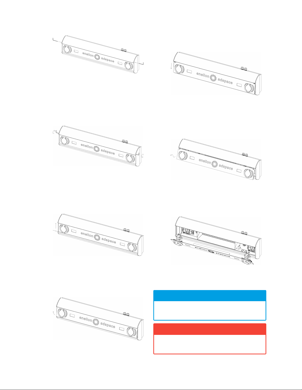
For installation, about 50 cm of power cable re-
serve from the expected installation position is recom-
mended.
HINT
For Wallbox Adspace devices, a reserve of
about 110 cm of the cable supplying power to
the left socket is recommended.
3.2. Recommended communication net-
work
Enelion devices support the Enelion Chain communica-
tion interface. For its implementation, a wired connec-
tion between the devices is required using an Ethernet
CAT 5 or CAT 6 cable.
For installation, leave about 50 cm of communication
cables from the expected installation position.
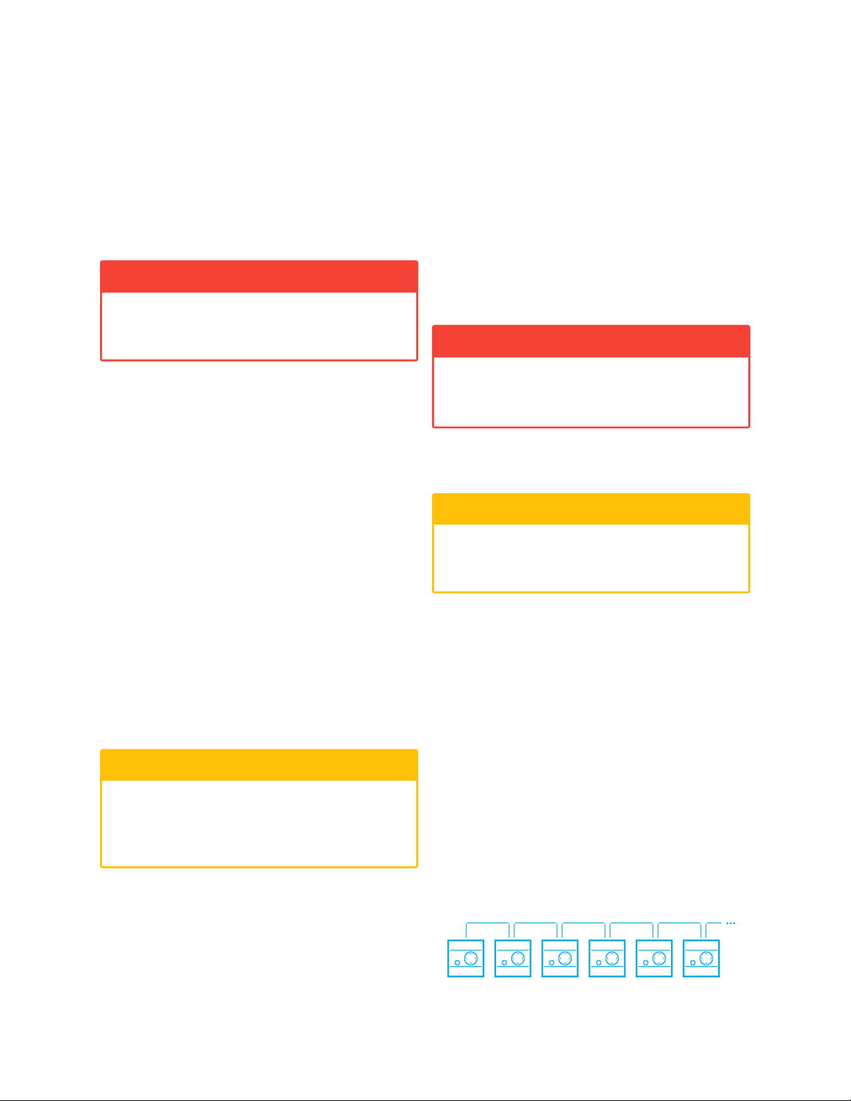
The network works in a serial topology where:
• the number of Enelion charging points does not
exceed 100 devices,
• the total length of the communication cable con-
necting the devices does not exceed 500 m.
Fig. 10: Enelion Chain network topology.
7 Design indications of the installation

Wallbox Adspace - Assembly manual 8 - 2021
Enelion devices equipped with the Enelion Bridge mod-
ule can use the Internet connection via the Ethernet in-
terface in the LAN network. In order to utilize this func-
tion, run the Ethernet CAT 6 cable to the device in which
the use of this option is expected.
INFO
Devices equipped with Enelion Bridge can also
use WiFi and GSM interfaces to ensure the In-
ternet connection, but they do not have require-
ments related to cable installation.
3.3. Location selection criteria
Wall-mounted Enelion devices may be installed both in-
ternally or externally.
The device has been designed to be installed near
parking spaces for electric vehicles. When used in the
vehicle collision hazard zone, the structure should be
secured with appropriate fenders painted in yellow and
black stripes (warning about the gauge).
Bear in mind that the national regulations may define
the space for the installation. The device should not be
located in a place of high exposure to sunlight, which
could cause overheating. Do not install the device near
heat sources or in small, closed spaces (e.g. in a box).
It is forbidden to install a power cord that does not com-
ply with the guidelines in section 3.1 Recommended
power connection. It is forbidden to install the device
in potentially explosive environment.
Local regulations for electrical installations, fire preven-
tion measures and accident prevention must be taken
into account, and escape routes at the installation site
must be provided.
It is forbidden to install the device in a location where
falling objects may damage the charger.
Before installation, make sure that the mounting space
for the device is sufficient.
Wallbox family devices should have at least:
1. 10 cm clearance on each side of the unit.
Stilo family devices should have at least:
1. 10 cm clearance on the right side of the unit.
2. 50 cm clearance above the top edge of the de-
vice.
3. 100 cm clearance below the bottom edge of the
device.
oWARNING
The manufacturer accepts no responsibility for
any damage resulting from failure to comply
with the above-mentioned recommendations.
8 Design indications of the installation

Wallbox Adspace - Assembly manual 8 - 2021
4. Assembly
oWARNING
Before commencing the installation, switch off
the power supplied to the cables.
4.1. Preparing the installation
1. Place the packaged Enelion Wallbox Adspace
horizontally, in accordance with the markings on
the packaging. Cut the package open along
the indicated line. Take the device out of the
cardboard box, remove the polystyrene protective
casing and put the device in the safe horizontal
position.
2. The polystyrene protection contains useful ac-
cessories necessary for the mounting of the de-
vice. Before recycling the packaging, collect
those accessories that include:
• 3 mm Allen key,
• cable gland plug,
• RFID configuration card.
3. Open Enelion Wallbox Adspace in accordance
with the instruction included in section 2.1 Open-
ing and closing Enelion Wallbox Adspace.
4.2. Selection of bolts and anchors
Enelion Wallbox Adspace is mounted on vertical sur-
face using bolts. The device has four mounting open-
ings. Additionally, the device is equipped with holds fa-
cilitating the assembly.
Fig. 11: Mounting holes of Enelion Wallbox Adspace as
seen from the back of the device.
Following the information listed below, choose the
appropriate method of assembly, depending on the
mounting surface:
1. four mounting holes are positioned on the plan of
a rectangle with dimensions of 960 mm x 96 mm
(width x height)
2. mounting holes have a diameter of 5,5 mm,
3. the device weighs between 2,8 kg – 3 kg,
4. mounting must provide stability for the device to
withstand significant forces affecting it when plug-
ging and unplugging the charging cable in the
socket.
oWARNING
Use all four mounting holes in the process of
installation. Failure to comply with the require-
ment will result in the loss of water and dust re-
sistance of the device, as a default classified as
IP 54. This can lead to damage or failure of
the charger, and consequently to loss of life or
health. The manufacturer is not responsible for
damage and injuries arising from failure to ob-
serve the above recommendations.
4.3. Cable routes
The default power cable entry (A entry) is at the top part
of the device.
It is possible to insert the power cables from the bottom
of the device by moving the gland by oneself. To do
this, remove the plugs at the bottom of the device.
The insertion of communication cables (B entry) is pos-
sible from the bottom of the device. This requires the
removal of the plug and the installation of a gland suit-
able for the type and number of communication cables
to be routed. The opening diameter for the communi-
cation cable gland is 19 mm.
9 Assembly

Wallbox Adspace - Assembly manual 8 - 2021
Fig. 12: Locations of cable entry points in Enelion Wall-
box Adspace.
The removal of plugs for the assembly of cable glands
should be performed according to the following guide-
lines:
1. place the device on a stable surface,
2. use a hammer and a flat-bladed screwdriver to
knock out the gland hole plug carefully.
The cable glands in the upper part of the device should
be put into the holes in the lower part of the device
and screwed to ensure tightness. The gland nut re-
quires a 32 mm, spanner and the gland requires a
30 mmspanner. After repositioning the glands, the
openings in the upper part of the device should be
closed with the plugs provided with the product.
The cable gland for communication cables should be
installed in accordance with the manufacturer’s instruc-
tions.
oWARNING
If the gland is repositioned by the user, the man-
ufacturer’s warranty for the tightness of the de-
vice in accordance with the IP54 class becomes
void. Correct performance of the operation en-
sures adequate tightness; however, the manu-
facturer reserves the right to refuse to repair un-
der warranty the damage resulting from the re-
location of the cable gland from the top to the
bottom of the device.
4.4. Mounting the device
INFO
The device has been equipped with a template
facilitating the installation.
1. Determine the final location of the device using
the attached template and the level and mark the
mounting holes. The template marks the mount-
ing holes, the outline of the rear wall of the device,
the axes of the glands (both in the version with a
gland in the upper and lower part of the device)
and the optimal cable lengths. Mounting holes
should be at least 5 cm from the edge of the wall
(in case of a recess, leave enough space on both
sides of the device to reach with the Allen key).
The axis of the power cables must coincide with
the axis of the glands marked on the template.
Make sure that the power cord:
• of the right socket is at least 300 mm long,
• of the left socket is at least 1000 mm long,
when measured from the edge of the device
marked on the template.
2. Make assembly holes and install expansion bolts.
Mounting holes should be made in accordance
with the specification of expansion bolts which
should be placed in the cleaned holes.
3. Make sure that there is no voltage in the power
cord.
4. Open the appliance as described in section 2.1
Opening and closing Enelion Wallbox Adspace.
5. Put the device in the target position by threading
the power cables through the glands.
6. Fasten the device with screws using a screw-
driver with a shaft length of at least 150 mm.
7. Screw on the power cable glands ensuring tight-
ness.
8. (Optional) Insert at least 300 mm of the commu-
nication cables into the device.
The device mounted in this way can be connected.
10 Assembly

Wallbox Adspace - Assembly manual 8 - 2021
5. Connection
5.1. Power connection
Enelion Wallbox Adspace comes in various types. De-
pending on which type is being installed, the power sup-
ply cables may be connected to the terminals or directly
to the approved integrated MID meter.
Charging module - Type 2 socket
with RCMB 6mA DC
Type 2
socket
Type 2
socket
Charging module - Type 2 socket
with RCMB 6mA DC
Terminal block Terminal block Terminal block Terminal block
Housing
Charging module - Type 2 socket
with RCMB 6mA DC Charging module - Type 2 socket
with RCMB 6mA DC
Variant 1 Variant 2
Housing
meter meter
fuse fuse
Fig. 13: Diagrams of connection types 1/2.
11 Connection

Wallbox Adspace - Assembly manual 8 - 2021
Variant 3 Variant 4
Charging module - Type 2 socket
with RCM B 6 mA DC
Charging module - Type 2 socket
with RCM B 6 mA DC
Type 2
socket
Type 2
socket
Charging module - Type 2 socket
with RCM B 6 mA DC
Charging module - Type 2 socket
with RCM B 6 mA DC
Type 2
socket
Type 2
socket
MID METER MID METER MID METER MID METER
Housing Housing
METER METER
fuse fuse
Fig. 14: Diagrams of connection types 2/2.
5.1.1. Standard power connection
INFO
For both charging sockets to function in Ene-
lion Wallbox Adspace the voltage must be sup-
plied to the electrical connection clamps of both
charge controllers. The steps described below
should be applied to the terminals of both charg-
ing sockets.
1. Run the left socket power supply cable along the
bottom part of the device below the backlight
shield.
2. Prepare the power supply cable.
Remove 200 mm of the main insulation off the
power supply cable. Terminate the individual
wires of the cable with fork (M4 or M5 size) or
sleeve terminals.
3. Insert the power supply cables into the terminals.
Fig. 15: Connection using fork terminals.
12 Connection

Wallbox Adspace - Assembly manual 8 - 2021
Fig. 16: Connection with solid conductors – wire.
4. Use a PZ2 end screwdriver to tighten the termi-
nals with 1.5Nm 1,5 N m torque.
Fig. 17: Electrical connection executed correctly.
5.1.2. Power connection in version with MID meter
INFO
For both charging sockets to function, in Ene-
lion Wallbox Adspace the voltage must be sup-
plied to the electrical connection clamps of both
charge controllers. The steps described below
should be applied to the terminals of both charg-
ing sockets.
1. Run the left socket power supply cable along the
bottom part of the device below the backlight
shield.
2. Prepare the power cord.
Remove 200 mm of the main insulation off the
power supply cable. Terminate the individual
wires of the cable with sleeve terminals.
3. Insert the power cables into the terminals of the
MID meter and tighten them.
Unless otherwise marked on the label of the de-
vice, make a standard connection in accordance
with the markings on the meter. The PE protec-
tive conductor should be connected to the pre-
pared coupling.
Fig. 18: Recommended connection when apply-
ing a MID meter.
MID meter communication connection should be done
according to the diagram below:
Fig. 19: MID meter communication connection.
HINT
The colors of the phase wires in Enelion Wall-
box Adspace may not match the colors of the
power cables, maintaining, however, the guide-
lines on Enelion Wallbox Adspace label. This is
a correct and expected situation when using the
phase sequence function.
5.1.3. RCM B Connection
Enelion RCM B – Residual Current Monitor type B ac-
cessory. Enelion RCM B in combination with the RCD
A used in the switchgear meet all safety requirements.
1. Connect the device to the dedicated socket on
the PilotBox board. [Fig. 20]
13 Connection

Wallbox Adspace - Assembly manual 8 - 2021
Fig. 20: PilotBox RCM B socket.
2. Pass through the RCM B hole four powering ca-
bles (All three phases and neutral cord.)
Fig. 21: RCM B connection
HINT
The way of cables through the RCMB hole does
not matter. The RCMB monitor could be freely
assembled on the socket cables or on the main
income cables.
INFO
More information in the User Manual.
5.2. Connection of communication wires
HINT
Both integrated charge controllers in Enelion
Wallbox Adspace are connected by a commu-
nication cable as a default. In the implementa-
tion of the Enelion Chain network, this section
should be treated as a section between devices
and all the guidelines described below should
be applied.
5.3. Enelion Chain
If the communication between the devices is expected
to be via Enelion Chain network, the cables should
be connected to the charge controller. Two cores of
the communication cable and the screen grounding are
used for communication. To connect correctly:
1. Prepare communication cables
2. (a) for devices at the beginning of the network,
select a pair of communication wires,
(b) for devices in a section of the network, pre-
pare the communication cables inserted into
the device by connecting together the cores
of the incoming and outgoing wires (in vari-
ant A) or move to the next step (in variant B,
check figures below).
Fig. 22: Incoming and outgoing communi-
cation cable connection (variant A)
14 Connection

Wallbox Adspace - Assembly manual 8 - 2021
Fig. 23: Incoming and outgoing communi-
cation cables (variant B)
3. Release the connector terminal by pressing the
button using a flathead screwdriver and insert the
wires into the respective locations. There will be
single wires for devices at the start and end of the
network.
Fig. 24: Diagram of Enelion Chain communica-
tion cables connection (variant A)
Fig. 25: Diagram of Enelion Chain communica-
tion cables connection (variant B)
4. Use termination for devices at the beginning and
end of the network. In case of variant A place
terminating jumper on the marked headers [Fig
28]. In case of variant B termination is done
by slide the switch down, to show white square.
In alternate version, if there is no switch, place
a jumper on two pins in the header inside the
charger marked by white line [Fig. 29].
Fig. 26: Termination diagram.
Fig. 27: A sample jumper.
Fig. 28: The place of applying the terminating
jumper (variant A)
15 Connection

Wallbox Adspace - Assembly manual 8 - 2021
Fig. 29: The place of applying the terminating
jumper (variant B)
5.4. Internet connections via Ethernet in-
terface in LAN network
To provide the Internet connection to a charger
equipped with Enelion Bridge module via Ethernet in-
terface:
1. Insert the Ethernet cable into the device through
the gland for communication cables.
2. Terminate the cable with the RJ45 connector ac-
cording to TIA-568A/B to 100BaseT.
Fig. 30: Termination of the Ethernet cable accord-
ing to TIA-568A/B to 100BaseT.
3. Connect the Ethernet cable to the
WAN/INTERNET socket of Enelion Bridge mod-
ule marked with number 2.
Fig. 31: Enelion Bridge module diagram.
5.5. Backlight power supply
The backlight module is powered from the terminals of
one of the charging controllers. It activates with the ap-
pearance of voltage in the charging controller terminals.
16 Connection

Wallbox Adspace - Assembly manual 8 - 2021
6. Maintenance
The device is designed to operate in temperatures from
−25 °C to 55 °C. The manufacturer does not guarantee
the proper functioning of the charging station in temper-
atures outside the specified range. Chargers that are
damaged because of exposure to temperatures below
−25 °C or above 55 °C are not covered under the war-
ranty. In case it is necessary to open the device, make
sure that it is disconnected from the power source. With
the device installed outdoors, make sure that there is no
precipitation or strong wind.
oWARNING
The device may only be opened by a qualified
and authorized person.
6.1. Cleaning
The correct way to clean the charger is to wipe the
housing with a microfiber cloth using a cleaning agent
dedicated to anodized aluminum. Plexiglas elements
(front panel) and plastic elements (socket) should be
cleaned with a microfiber cloth using a cleaning agent
dedicated to cleaning windowpanes. Other cleaning
methods (e.g. wire brush) may lead to the damage of
the device housing. Damage resulting from improper
cleaning of the device does not constitute grounds for
warranty claims.
oWARNING
The device meets the IP 54 standard. There-
fore, it is forbidden to wash the charger with
pressure washers, garden hoses, shower or any
other water stream sources.
17 Maintenance

Wallbox Adspace - Assembly manual 8 - 2021
7. Technical data
7.1. Enelion Wallbox Adspace
Electrical data
Routing of the power cord Surface mounted
Power cord cross-section
Recommended minimum cross-section
• 2 cords 5 x 6,0 mm2(32 A nominal current)
Supply voltage (Europe) 3 x230 V/400 VAC (+-10%)
Voltage frequency 50 Hz/60 Hz
Network type TN, TT
(IT per special request)
Overvoltage category III according to EN 60664–1
Rated short-circuit current Effective value < 6 kA according to EN 61439–1
Overcurrent protection Not included. Protection to be made in accordance with
the locally valid regulations and according to the type of
the device.
Protection Class Class I
Socket type 2x Type 2, standard socket 32 A/400 VAC in accordance
with EN 62196–1
Mechanical data
Dimensions (width x height x depth) 1000 mm x 249 mm x 156 mm
Weight 7 kg ±5%
IP Class IP54
Mechanical strength class IK10
Interfaces
Charging network development Enelion Chain
Add-ons
• Enelion MID
• Enelion Bridge
• Enelion LTE
• Enelion RCM B
RFID MIFARE cards compliant with ISO 14443
18 Technical data

Wallbox Adspace - Assembly manual 8 - 2021
Ambient conditions
Working temperature from −25 °C do 55 °C
Storage temperature range from −40 °C do 80 °C
Permitted relative air humidity from 5% do 95%
Elevation above the sea level maximum 2000 m
Signs of installation faults
Damaged varistors on PilotBox It means faulty connection powering cords
oWARNING
Above information may be the basis for exclu-
sion of warranty.
19 Technical data
Table of contents
Other Enelion Automobile Accessories manuals
Popular Automobile Accessories manuals by other brands

CrimeStopper
CrimeStopper CS-6604 installation manual

Allen Sports
Allen Sports 542RR-R instructions

Accessory Power
Accessory Power ReVIVE series quick start guide

KW automotive
KW automotive 685 10 456 installation instructions

Bulldog Security
Bulldog Security Titan Fitting instructions

LEGRAND
LEGRAND ecotap DC 120 manual