Enerdis C.A 2150-E User manual

INSTRUCTIONS MANUAL
VOLTMETER/ AMMETER DC/ AC (TRMS)
C.A 2150
-
E
INSTRUCTION MANUAL
ENGLISH

2
1
OVERVIEW ..........................................................................................................................................................4
1.1
Introduction to model CA2150-E ................................................................................................................................4
2
GETTING STARTED..............................................................................................................................................5
2.1
Power Supply and connectors ....................................................................................................................................9
2.2
iring overview ...................................................................................................................................................... 10
2.3
Instrument front view.............................................................................................................................................. 11
3
INPUT PROGRAMMING.....................................................................................................................................12
3.1
DC/ AC VOLTAGE INPUT IRING (RANGES: 2, 20, 200, 600 V)................................................................................ 13
3.2
1 or 5 DIRECT AMPERES INPUT IRING ................................................................................................................. 14
3.3
200 mA INPUT IRING........................................................................................................................................... 15
3.4
CURRENT TRANSFORMER 1A / 5A AC IRING....................................................................................................... 16
3.5
SHUNT 50/ 60/ 100 mV DC/ AC IRING.................................................................................................................. 17
4
DISPLAY PROGRAMMING .................................................................................................................................1
4.1
Scale ...................................................................................................................................................................... 19
4.1.1
Description menu configuration Display ............................................................................................................. 20
5
KEYBOARD AND CONNECTOR FUNCTIONS.......................................................................................................22
5.1
Keyboard functions.................................................................................................................................................. 22
5.2
Connector functions ................................................................................................................................................ 24
5.2.1
Logic functions diagram.................................................................................................................................... 25
5.2.2
Table of programmable functions...................................................................................................................... 26
5.2.3
Programming the functions............................................................................................................................... 27
6
PROGRAMMING LOCK OUT BY SOFTWARE.......................................................................................................2
6.1
Security menu diagram............................................................................................................................................ 29
7
OUTPUT OPTIONS.............................................................................................................................................32
7.1
Setpoints output...................................................................................................................................................... 34
7.1.1
Introduction ..................................................................................................................................................... 34
7.1.2
Description of operation.................................................................................................................................... 35
7.1.3
Installation....................................................................................................................................................... 36
7.1.4
iring.............................................................................................................................................................. 36
7.1.5
Technical specifications..................................................................................................................................... 37
7.1.6
Setpoints menu diagram ................................................................................................................................... 38
7.1.7
Direct access to the setpoints value programming ............................................................................................. 39

3
7.2
RS232 / RS485 Output ............................................................................................................................................ 40
7.2.1
Introduction ..................................................................................................................................................... 40
7.2.2
iring.............................................................................................................................................................. 41
7.2.3
Connection in a network by RS485 link.............................................................................................................. 42
7.2.4
RS output menu diagram .................................................................................................................................. 44
7.3
Analog output ......................................................................................................................................................... 49
7.3.1
Introduction ..................................................................................................................................................... 49
7.3.2
Installation of Analog 4-20mA and Analog 0-10V option..................................................................................... 49
7.3.3
Connection....................................................................................................................................................... 50
7.3.4
Technical specifications..................................................................................................................................... 51
7.3.5
Analog output menu diagram............................................................................................................................ 51
WARRANTY .......................................................................................................................................................52
9
TECHNICAL SPECIFICATIONS...........................................................................................................................53

4
1 OVERVIEW
1.1 Introduction to model CA2150-E
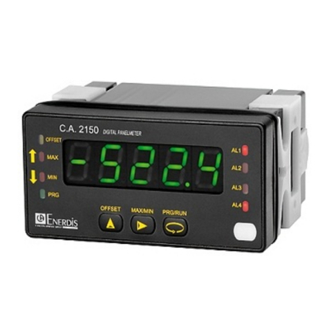
The CA2150-E model from the CA2150 is a digital multifunction instrument which allows the user to program the input as a:
- DC VOLTMETER
- AC VOLTMETER (TRMS)
- DC AMMETER
- AC AMMETER (TRMS)
The basic instrument is a soldered assembly composed of a main board, a tricolor programmable display and a power circuit.
Standard features of the basic instrument include the reading of the input variable as well as remote hold, reading and
memorisation of max and min values (peak/ valley) and a full complement of programmable logic functions.
In addition, a variety of plug-in output cards can be installed at any time to meet further system requirements:
COMMUNICATION
Serial RS232C
Serial RS485
CONTRÔLE
Analogue 4-20mA
Analogue 0-10V
2 Relays SPDT 8A
4 Relays SPST 5A
4 NPN output
All the output options are opto isolated from input signal and power supply.

5
2 GETTING STARTED
Packing contents
• Instruction manual in English including declaration of conformity.
• Digital panel meter CA2150-E.
• Accessories for panel mounting (sealing gasket and fixing clips).
• Accessories for wiring connections (plug-in terminal block connectors with a fingertip key).
• iring label stuck to the CA2150-E case.
• 4 sets of labels with engineering units.
Check the packing contents.
Programming instructions
• The Instrument has software that via keyboard allows accessing to several independents programming menus for
configuration of the input, the display and the logic functions. If additional options are installed (serial outputs, analogue output
and relays output, once recognised by the instrument, they activate their own programming software.
• Programming can also be done via PC with free software available in our website web www.chauvin-arnoux.com provided
that the serial option, RS232 or RS485, has been installed.
Read carefully this section.
Programming lock-out (Page 2 ).
Software allows total programming lockout but also selective lockout of the programming parameters.
• The instrument is delivered from factory with unlocked programming, e.g., with all the programming levels accessible to the
operator
Write down the security code and keep it in a secure place.

6
The figure below shows the locations of the different output options available.
Up to three output options can be installed and operate simultaneously:
- 4-20mA ou 0-10V ( only one )
- RS232C ou RS485 ( only one)
- 2 RELAYS, 4 RELAYS ou 4 OPTOS ( only one ). Dimensions and mounting
Front: 96 x 48 mm Depth: 60 mm
Panel cut-out : 92 x 45 mm
CLEANING: frontal cover should be cleaned only with a soft cloth
soaked in neutral soap product.
DO NOT USE SOLVENTS

7
How to get into programming mode?
First, plug the instrument to the corresponding supply, automatically a display test will be done and after that the software version
will be shown then the instrument will go to work mode. Second, press the key to enter into the programming mode, the
indication "-Pro-" will appear on the display then.
How to store programmed parameters?
If we want to save the changes that we have done in the programming, we must complete the programming of all the parameters
contained in the routine we are in. In the last step of the routine, as a result of pressing on the
key, “StorE” will de displayed
during a few seconds, meanwhile all the data are stored in memory. Then the instrument will go back to working mode.
How is programming routine organised?
Programming software is composed by a number of menus and submenus hierarchically organized. On figure below, beginning
with indication "-Pro-", press repeatedly
to get access to programming menus. Modules 3, 4 and 5 will only be shown if the
option for setpoints, analogue output or RS option has been plugged in. Selecting one menu, the access to the different
programming submenus is done by pressing .
Module selection level

8
Accessing to programmed parameters
Thanks to the tree structure, the programming routines allow to access to change one parameter without passing through the
whole list of parameters.
To advance through programming
The progress through the programming routines is done by pressing key.
In general, the steps to be done will be push key a certain number of times to select an option and push key to validate
the change and going forward to the next step of the program.
The numerical values are programmed digit by digit as explained in the next paragraph.
Programming numerical values
hen the parameter is a numerical value, the display will show the first of the digit to be programmed blinking.
The method of introducing a value is as follow:
Digit selecting: Press repeatedly the key to shift from left to right over all the display digits.
Changing the digit value: Press repeatedly the key to increase the value of blinking digit until it has the desired value, (0
to 9).
The minus sign is programmed depending on the variable type. A variable that represents the value of an input will be able to take
a value in the range -19999 to 19999, without taking into account the decimal point. hen change the first digit, this shows
values from (-1) (-), (0), (1).
A variable that represents a display value will be able to take a value in the range -19999 to 19999, without taking into account
the decimal point. In these case the first digit shows (-1) (-), (0), (1).
Selecting an option from the list
hen the parameter is an option to be chosen among different possibilities, the key allows you to browse through the list of
options until you find the desired parameter.

9
2.1 Power Supply and connectors
WIRING and POWER SUPPLY RANGE
CA2150-E1
85 V – 265 V AC 50/ 60 Hz ou 100 – 300 V DC
CA2150-E2
22 – 53 V AC 50/ 60 Hz ou 10,5 - 70 V DC
Borne 1: Phase
Borne 2: Neutral
NOTE: When DC power supply (direct)
polarity in connector CN1 is indistinct.
WARNING: If not installed and used in accordance with these
instructions, protection against hazards may be impaired.
In order to guarantee the electromagnetic compatibility, the following
guidelines should be kept in mind:
Power supply wires may be routed separated from signal wires.Never run
power and signal wires in the same conduit.Use shielded cable for signal
wiring and connect the shield to the ground of the indicator. The cables
section should be >0.25 mm
2
INSTALLATION
To meet the requirements of the directive EN61010
-
1, where the unit is
permanently connected to the mains supply, it is obligatory to install a circuit
breaking device easy reachable to the operator and clearly marked
as the
disconnect device
.
CONNECTEURS
CN1
To perform wiring connections, strip the wire leaving from 7 and 10 mm
exposed to air and insert it in the proper terminal while pushing the fingertip
down to open the clip inside the connector as indicated in the figures.
Each terminal accep
ts cables of section between 0.08 mm² and 2.5 mm² (A G
28 ÷ 12).
CN2 et CN3
To perform wiring conections, strip the wire leaving from 5 and 6
mm exposed to air and insert it in the proper terminal while pushing the finger
tip
down to open the clip inside the connector as indicated in the figures.
CN2
Each terminal accepts cables of section between 0.08 mm² and 1.5 mm²
(A G 28 ÷ 14).
CN3
Each terminal accepts cables of section between 0.08 mm² and 0.5 mm²
(A G 28 ÷ 20).

10
2.2 Wiring overview
ATTENTION : CA2150-E INPUT WIRING SIGNAL
Before connecting signal wires, the Signal and Input Range should be verified for proper position.
CAUTION:
Connect Only one input signal range to the meter. Hazardous signal levels may be present on
unused inputs.
CAUTION: The isolation rating of the input common of the meter with respect to the option card common and
to the Logical Functions common (if used) is 250 Vrms and 500 Vrms with respect to AC Power (terminals 1
and 2 of connector CN1). To be certain that the ratings are not exceeded, these voltages should be verified by
a high-voltage meter before wiring the meter.
CAUTION:
1- here possible, connect the neutral side of the signal (including current shunts) to the input common of
the meter. If the input signal is sourced from an active circuit, connect the lower impedance (usually
circuit common) to the input signal common of the meter. (pin 1 CN2)
2- For phase to phase line monitoring where a neutral does not exist, or for any other signal input in which
the isolation voltage rating is exceeded, an isolating potential transformer must be used to isolate the
input voltage from earth. ith the transformer, the input common of the meter can then be earth
referenced for safety.
3- hen measuring line currents, the use of a current transformer is recommended. If using external
current shunts, insert the shunt in the neutral return line. If the isolation voltage rating is exceeded, the
use of an isolating current transformer is necessary.

11
2.3 Instrument front view
-Pro- Run
1 Not active in Programming mode 1 AC measurement indication (TRMS)
2 Not active in Programming mode 2 Displayed value corresponds to max. value
3 Not active in Programming mode 3 Displayed value corresponds to min. value
4 Indicates that you are in Programming mode 4 Not active in Run mode
5 Indicates SET 1 is being programmed 5 Indicates that SET 1 is activated
6 Indicates SET 2 is being programmed 6 Indicates that SET 2 is activated
7 Indicates SET 3 is being programmed 7 Indicates that SET 3 is activated
8 Indicates SET 4 is being programmed 8 Indicates that SET 4 is activated
9 Key that allows modifying numerical value 9 Allows direct access to SETPOINTS value prog.
10 Key that allows moving the blinking digit 10 Allows visualization of of MAX and MIN value
11 Key that allows stepping forward in prog. Menu 11 Allows access to Programming mode
12 Display tricolor 12 Display tricolor
13 Label with engineering unit 13 Label with engineering unit

12
3 INPUT PROGRAMMING
The figure below shows the input configuration menu (CnInP). Divided into four submenus, each one corresponding to the
programming of the different types of input: Volt dc, Volt ac, Amp dc, Amp ac. Once the type of signal has been selected you have
then to select the range. Usually the 100, 60, 50 mV (nU) ranges are shunts signals.

13
3.1 DC/ AC VOLTAGE INPUT WIRING (RANGES: 2, 20, 200, 600 V)
Note: MAXIMUM TENSION APPLICABLE IS: 600 V DC/ AC
If the input range is not superior to 2 V then specific input for 2 V can be used with wiring indicated in figure 2
Description CN2
PIN 1 = COMMUN
PIN 2 = SHUNT/ 2 V
PIN 3 = 200 mA
PIN 4 = 1A / 5A
PIN 5 = 20/ 200/ 600 V
Read recommendations
page 10
Figure 2

14
3.2 1 or 5 DIRECT AMPERES INPUT WIRING
Description CN2
PIN 1 = COMMUN
PIN 2 = SHUNT/ 2 V
PIN 3 = 200 mA
PIN 4 = 1A / 5A
PIN 5 = 20/ 200/ 600 V
Read recommendations
page 10

15
3.3 200 mA INPUT WIRING
Description CN2
PIN 1 = COMMUN
PIN 2 = SHUNT/ 2 V
PIN 3 = 200 mA
PIN 4 = 1A / 5A
PIN 5 = 20/ 200/ 600 V
Read recommendations
page 10

16
3.4 CURRENT TRANSFORMER 1A / 5A AC WIRING
VERY IMPORTANT: The connection wires between the transformer and the instrument have to be as short as possible and
their section has to allow that the total resistance of the circuit multiplied by the maximum intensity (5 A), do not exceed the
power of the current transformer being used; otherwise a loss of linearity in the measurement will occur.
Example: ith a 100A/ 5 Transformer of 2 VA, the maximum resistance, in order not to alterate the measurement, will have to be:
2/25= 0,08 ohms, if we subtract the value of the internal shunt that is 0,014 ohm, the result remaining will be 0,066 ohm that
divided by /2 will give 0,033 ohm maximum for each wire from the transformer to the instrument.
Description CN2
PIN 1 = COMMUN
PIN 2 = SHUNT/ 2 V
PIN 3 = 200 mA
PIN 4 = 1A / 5A
PIN 5 = 20/ 200/ 600 V
Read recommendations
page 10

17
3.5 SHUNT 50/ 60/ 100 mV DC/ AC WIRING
NOTE: we recommend braiding the cables used to wire the shunt to the instrument in order to avoid as much as possible to pick-
up interferences.
Description CN2
PIN 1 = COMMUN
PIN 2 = SHUNT/ 2 V
PIN 3 = 200 mA
PIN 4 = 1A / 5A
PIN 5 = 20/ 200/ 600 V
Read recommendations
page 10

18
4 DISPLAY PROGRAMMING
NOTE: In the programming of the 600 V
DC or V AC range, 600,0 is accepted as a
maximum ,in both ScAL and tEAcH
methods.

19
4.1 Scale
Scaling consists of assigning a display value to each input signal value.
With CA2150-
E it is achieved by programming two coordinates
(input1, display1) and (input2, disp
lay2), between which is
established a linear relation where to each input signal value
corresponds a display value.
The relationship can be direct or reversed. In order to obtain
more accuracy, points 1 and 2 should be located approximately
at both extremes of the process.

20
4.1.1 Description menu configuration Display
SCAL method
The input and display values are programmed manually. This method can be used when the value of the signal supplied by the
transducer at each points of the process is known.
tEACH method
The input values are introduced directly from the signal present in the input connector when each point is programmed. The
display values are programmed manually.
This method can be used when it is possible to bring the process to the conditions of each one of the points to be programmed.
Programming scale points
Input points
- 19999
to
99999
Display points
- 19999
to
19999
Display decimal point
0 0.0 0.00 0.000 0.0000
Accessible from the SCAL or tEACH menu, following the first display point. Once acceded to it , it will start to blink in its present
position and through the key will be able to shift to another position.
Moreover it will also affect, as well as the display points, the setpoints value and the value of the analog output scale, in case the
corresponding option has been installed.
Table of contents
Other Enerdis Measuring Instrument manuals
Popular Measuring Instrument manuals by other brands
PCB Piezotronics
PCB Piezotronics 3741B1250G Installation and operating manual

Kanomax
Kanomax ANEMOMASTER A031 Operation manual

Compu-Flow
Compu-Flow C6 quick start guide
Milltronics
Milltronics HydroRanger Plus instruction manual
Apera
Apera DO850 instruction manual
Koehler
Koehler ADA5000 Operation and instruction manual
