Enerdis Enerium 100 User manual

MS1 – 735
2
FOR
ENERIUM
2
Ed04
U
ENERIUM
100/110/200/210/300/310
P
OWER
232 / 332 / 333
Power
Monitor
U
SER MANUAL
100/110/200/210/300/310
OWER
M
ONITORS
232 / 332 / 333

U
SER MANUAL
–
ENERIUM
100/200/300
MS
1
-
7352 ENERIUM100/200/300_ Ed0
4
User
Manual
Page
2
/
86
TABLE OF CONTENTS
1
SAFETY ..................................................................3
1.1
P
REAMBLE
........................................................... 3
1.2
I
NITIAL PRECAUTIONS
............................................. 3
1.3
C
LEANING INSTRUCTIONS
........................................ 3
2
WARRANTY, RESPONSIBILITY AND INTELLECTUAL
PROPERTY .....................................................................4
2.1
W
ARRANTY
.......................................................... 4
2.2
I
NTELLECTUAL PROPERTY RIGHTS
.............................. 4
2.3
M
AINTENANCE
..................................................... 4
2.4
E
QUIPMENT END
-
OF
-
LIFE
........................................ 4
3
OVERVIEW ............................................................5
3.1
P
ACKING
............................................................. 5
3.2
O
PTIONAL ACCESSORIES AND DOCUMENTATION
.......... 5
3.3
O
VERVIEW
...........................................................
3.4
M
ODEL COMPARISON
............................................ 7
3.5
T
ERMINOLOGY
..................................................... 8
4
MECHANICAL CONSTRUCTION ..............................9
4.1
P
REAMBLE
........................................................... 9
4.2
V
ERSION WITH DISPLAY
(M
ODELS
100/200/300) ..... 9
4.3
V
ERSION WITHOUT DISPLAY
(M
ODELS
110/210/310)
11
5
FRONT VIEW ........................................................ 12
5.1
D
ISPLAY SCREEN
.................................................. 12
5.2
O
PTICAL INTERFACE
............................................. 14
6
REAR VIEW .......................................................... 16
.1
M
EASUREMENT INPUTS
........................................ 1
.2
A
UXILIARY SOURCE
.............................................. 20
.3
O
PTIONAL CARDS
................................................ 21
.4
C
ARD OPTION
-
2
ANALOG OUTPUTS
....................... 22
.5
C
ARD OPTION
-
2
ANALOG INPUTS
.......................... 23
.
C
ARD OPTION
-
2
DIGITAL OUTPUTS
........................ 24
.7
C
ARD OPTION
-
2
DIGITAL INPUTS
........................... 25
.8
RS485
COMMUNICATION
.................................... 2
.9
E
THERNET COMMUNICATION
................................. 28
7
MAIN SCREEN AND MAIN MENUS ....................... 3
7.1
M
AIN SCREEN
..................................................... 30
7.2
E
LECTRICAL QUANTITIES AND UNITS
........................ 31
7.3
M
ENUS AND SUB
-
MENUS
..................................... 32
8
MEASUREMENTS SCREEN .................................... 33
8.1
T
HE SCREENS
...................................................... 33
8.2
D
ISPLAY RULES
................................................... 3
9
ENERGIES SCREEN ............................................... 38
9.1
T
HE SCREENS
...................................................... 38
9.2
E
NERGY DISPLAY RULES
........................................ 39
1
SERVICES SCREEN ............................................ 4
10.1
T
HE SCREENS
...................................................... 40
11
ALARMS SCREEN .............................................. 42
11.1
T
HE SCREENS
...................................................... 42
12
CUSTOM SCREENS ........................................... 44
13
CONFIGURATION SCREEN ................................ 45
13.1
E
LECTRICAL NETWORK
.......................................... 4
13.2
RS485
COMMUNICATION
.................................... 48
13.3
R
EMOTE
E
THERNET COMMUNICATION
.................... 50
13.4
D
ISPLAY
............................................................ 51
13.5
P
ASSWORD
....................................................... 52
13.
D
EFAULT PARAMETERS
........................................ 53
13.7
P
ARAMETERS NOT MODIFIABLE BY THE KEYBOARD
..... 53
14
HARMONICS SCREEN ...................................... 54
14.1
T
HE SCREENS
..................................................... 54
15
PHASOR DIAGRAMS SCREEN ........................... 55
15.1
T
HE SCREENS
..................................................... 55
16
POWER QUALITY SCREEN ............................... 58
1 .1
T
HE SCREENS
..................................................... 58
17
WAVEFORMS MANAGEMENT ......................... 64
18
LOAD CURVES ................................................. 65
19
TREND CURVES ............................................... 66
2
LOCAL AND REMOTE COMMUNICATION......... 67
20.1
E.S
ET AND
E.V
IEW APPLICATIONS
.......................... 7
20.2
S
PECIFIC APPLICATION
......................................... 7
21
CHARACTERISTICS ........................................... 69
21.1
M
EASUREMENTS
................................................ 9
21.2
L
OAD CURVES
.................................................... 70
21.3
A
LARMS
........................................................... 70
21.4
A
NALOG OUTPUTS
.............................................. 70
21.5
T
REND CURVES
................................................... 71
21.
I
NHERENT ERRORS
.............................................. 71
21.7
E
NVIRONMENTAL CONSTRAINTS
............................ 73
21.8
S
AVING INFORMATION
......................................... 74
22
FORMULAE AND CALCULATION METHODS ..... 75
22.1
C
ONVENTION
..................................................... 75
22.2
P
HASE VOLTAGES
................................................ 75
22.3
L
INE VOLTAGES
.................................................. 75
22.4
C
URRENT
.......................................................... 75
22.5
R
EAL POWER
..................................................... 7
22.
P
OWER ROTATION DIRECTION
............................... 7
22.7
R
EACTIVE POWER
............................................... 7
22.8
A
PPARENT POWER
.............................................. 7
22.9
P
OWER FACTOR
................................................. 77
22.10
C
OS
(
Φ
) ........................................................ 77
22.11
P
EAK FACTOR
................................................. 77
22.12
T
AN
(
Φ
) ........................................................ 78
22.13
F
REQUENCY
................................................... 78
22.14
H
ARMONICS
.................................................. 78
22.15
T
OTAL HARMONIC DISTORTION
.......................... 78
22.1
E
NERGY AND ENERGY METERING
........................ 79
22.17
U
NBALANCE
.................................................. 79
22.18
P
HASE ORDER
................................................ 80
22.19
H
OUR METER
................................................. 80
22.20
A
VERAGE MEASUREMENTS
............................... 80
22.21
C
ALCULATION OF MINIMA
................................ 82
22.22
Q
UANTITY MINIMA
......................................... 82
22.23
M
INIMA OF AVERAGE QUANTITIES
..................... 83
22.24
C
ALCULATION OF MAXIMA
................................ 83
22.25
Q
UANTITY MAXIMA
......................................... 83
22.2
M
AXIMA OF AVERAGE QUANTITIES
..................... 84
22.27
A
NALOG INPUTS
............................................. 85

U
SER MANUAL
–
ENERIUM
100/200/300
MS
1
-
7352 ENERIUM100/200/300_ Ed0
4
User
Manual
Page
3
/
86
1 S
AFETY
1.1 Preamble
Read the following recommendations before installing and using the device.
You have just purchased an ENERIUM 100, 110, 200, 210, 300 or 310 power monitor. Thank you for
choosing it.
Make sure the device is intact and undamaged as soon as you receive it. In the event of any problems,
please contact the after-sales department for any repairs or replacements.
To get best use from your device please read this manual carefully and apply its storage, installation
and operating instructions with care.
The device described in this manual is intended to be used by trained staff only.
Any maintenance operations must be carried out by qualified and authorised personnel only.
For correct and safe use and for all maintenance operations it is essential that staff follow standard
safety procedures.
This device is intended to be used in Category III, pollution degree 2 installation conditions in
accordance with IEC 61010-1.
Before installation, check that the supply voltage matches that of the ENERIUM device.
1.2 Initial precautions
1.2.1 Safety precautions
Before installing this electrical device and any associated peripherals, check that the power is
disconnected and isolated in accordance with current safety norms.
1.2.2 Precautions against parasitics
Although the ENERIUM is protected from electrical and electromagnetically induced interference, keep
away from the immediate vicinity of equipment generating significant electrical noise (high-power
switches, busbars, etc.) The quality of data communication on the data bus depends heavily on taking
such precautions.
1.2.3 Precautions in the event of breakdowns
When safe operation is no longer possible, the instrument must be switched off and isolated. This
applies when:
•The device is visibly damaged during operation (whether the device still operates or not),
•The device does not work after prolonged storage in poor conditions,
•The device no longer works following severe damage during transport.
1.3 Cleaning instructions
When the monitor is disconnected from the mains, clean the outer surface using only a dry cloth. Do not
use abrasives or solvents. Prevent the connector terminals getting wet.

U
SER MANUAL
–
ENERIUM
100/200/300
MS
1
-
7352 ENERIUM100/200/300_ Ed0
4
User
Manual
Page
4
/
86
2 W
ARRANTY
,
R
ESPONSIBILITY AND
I
NTELLECTUAL
P
ROPERTY
2.1 Warranty
Unless expressly stipulated, the warranty runs for twelve months after the date of supply of the monitor
(extract from our General Conditions of Sale, available on request).
2.2 Intellectual property rights
This manual is the property of ENERDIS and is protected by copyright. It may not be distributed,
reproduced, or translated, in whole or in part, in any manner and in any form whatsoever.
ENERIUM is a registered ENERDIS trademark.
2.3 Maintenance
As no electrical or electronic part is end user-replaceable, the monitor must be returned to the
Manumesure after-sales service centre.
2.4 Equipment end-of-life
This product falls within the scope of the Directive 2012/19/CE on waste electrical and electronic
equipment (WEEE).
Contact the company ENERDIS for information regarding the dismantling and end of life equipment.

U
SER MANUAL
–
ENERIUM
100/200/300
MS
1
-
7352 ENERIUM100/200/300_ Ed0
4
User
Manual
Page
5
/
86
3 O
VERVIEW
3.1 Packing
Each delivered product should contain, at least, the following parts:
Designation No. Off
ENERIUM 100,110, 200, 210, 300 or 310 power monitor 1
CD-ROM containing:
This manual in pdf format
E.Set configuration software (with a 30-day trial version of E.View/E.View+)
The USB driver for the optical head accessory
1
Simplified operating instructions (A4 format) 1
ENERIUM 100, 200 or 300 table brackets 4
ENERIUM 110, 210 or 310 DIN rail brackets 2
Alternative parts depending on the option chosen:
Designation No. Off
Removable connectors for optional cards 0 to 4
3.2 Optional accessories and documentation
Designation Comment Code
USB optical head To enable local communication P01330401
E.View software Display software (Tabular) P01330401
E.View+ software Display software (Graphical) P01330401
E.Online software Multi-energy application software P01335075
Mapping and control words manual Manual MS0-7423
Load curves operating manual Manual MS0-7389
Recording curves operating manual Manual MS0-7390
User manual power quality measurements
Manual MS1-7530
DIN rail and cabinet base fixing kit Allows fitting on DIN rails and to the cabinet base P01330401
E.Set / E.View / E.view+
manual User manual MS0-7376
Firmware update Instruction manual MS0-7419

MS
1
-
7352 ENERIUM100/200/300_ Ed0
3.3 Overview
ENERIUM 100, 110, 200, 210, 300 and 310 power monitors are 144 x 144 format monitors, conforming
to DIN 43700, for electrical networks of all types, for all measurement, display and
applications on low and medium voltage networks.
ENERIUM 100, 110, 200, 210, 300 and 310 conform to the NF EN 61557
standard.
ENERIUM 100 and 110 conform
ENERIUM 200 and 210 conform
ENERIUM 300 and 310 conform
ENERIUM power monitors process more than 50 network quantities (U, V, I, P, Q, S, PF, tan
reactive and apparent energy, THD, etc.).
The infor
mation collected is available on the front panel of the monitor in 5 languages, via a backlit LCD
display, as
well as via an RS485 digital output using ModBus/RTU or ASCII, or Ethernet using
Modbus/TCP.
One or more optional outputs generate an alarm signal
It can be programmed locally or remotely, enabling the monitor to be integrated into an installation
rapidly.
The power monitor is available in six different models: ENERIUM 100, 110, 200, 210, 300 and310.
Models 110, 210 and 310 have no display; equivalent models with a display are the 100, 200 and 300.
(1) Source : http://www.gimelec.fr
U
SER MANUAL
–
ENERIUM
7352 ENERIUM100/200/300_ Ed0
4
User
Manual
ENERIUM 100, 110, 200, 210, 300 and 310 power monitors are 144 x 144 format monitors, conforming
to DIN 43700, for electrical networks of all types, for all measurement, display and
applications on low and medium voltage networks.
ENERIUM 100, 110, 200, 210, 300 and 310 conform to the NF EN 61557
ENERIUM 100 and 110 conform
to
the (1) (IM2) 232 measurement index.
ENERIUM 200 and 210 conform
to
the (1) (IM2) 332 measurement index.
ENERIUM 300 and 310 conform
to
the (1) (IM2) 333 measurement index.
ENERIUM power monitors process more than 50 network quantities (U, V, I, P, Q, S, PF, tan
reactive and apparent energy, THD, etc.).
mation collected is available on the front panel of the monitor in 5 languages, via a backlit LCD
well as via an RS485 digital output using ModBus/RTU or ASCII, or Ethernet using
One or more optional outputs generate an alarm signal
, send pulse counts or manage analog outputs.
It can be programmed locally or remotely, enabling the monitor to be integrated into an installation
The power monitor is available in six different models: ENERIUM 100, 110, 200, 210, 300 and310.
Models 110, 210 and 310 have no display; equivalent models with a display are the 100, 200 and 300.
The ENERIUM 300 monitor
ENERIUM
100/200/300
Page
6
/
86
ENERIUM 100, 110, 200, 210, 300 and 310 power monitors are 144 x 144 format monitors, conforming
to DIN 43700, for electrical networks of all types, for all measurement, display and
supervisory
-12 power measurement
the (1) (IM2) 232 measurement index.
the (1) (IM2) 332 measurement index.
the (1) (IM2) 333 measurement index.
ENERIUM power monitors process more than 50 network quantities (U, V, I, P, Q, S, PF, tanφ, real,
mation collected is available on the front panel of the monitor in 5 languages, via a backlit LCD
well as via an RS485 digital output using ModBus/RTU or ASCII, or Ethernet using
, send pulse counts or manage analog outputs.
It can be programmed locally or remotely, enabling the monitor to be integrated into an installation
The power monitor is available in six different models: ENERIUM 100, 110, 200, 210, 300 and310.
Models 110, 210 and 310 have no display; equivalent models with a display are the 100, 200 and 300.

U
SER MANUAL
–
ENERIUM
100/200/300
MS
1
-
7352 ENERIUM100/200/300_ Ed0
4
User
Manual
Page
7
/
86
3.4 Model comparison
The table below shows the main characteristics of the 100, 110, 200, 210, 300 and 310 models.
Enerium
100
Enerium
110
Enerium
200
Enerium
210
Enerium
300
Enerium
310
Measurements
Calculation and measurement of the
neutral current
3- or 4-wire capability
Tan ϕ
Harmonics up to order 25 25 50 50 50 50
400 Hz network - - - - - -
EN 50160 - - - -
Waveforms (64 samples per cycle) - - - -
Display
Custom screens
-
-
-
Power Quality - - - -
I/O cards
Optional card
(1)
4 4 4 4 4 4
Alarms
Basic 16 16 16 16 16 16
Global 8 8 8 8 8 8
Event journal records 1024 1024 1024 1024 1024 1024
Curves
Load curve - -
8
quantities
chosen
from 10
possible
ones
(2)
8
quantities
chosen
from 10
possible
ones
(2)
8
quantities
chosen
from 10
possible
ones
(2)
8
quantities
chosen
from 10
possible
ones
(2)
Recording curve
Communication
Optical (front panel)
-
-
-
Optical (rear panel)
Ethernet (Modbus / TCP)
(3)
RS485 (Modbus RTU or ASCII)
(3)
IP address parameters at the front
-
-
-
Graphs
Phasor
-
-
-
Harmonics - -
-
-
Fixing
LCD display
-
-
-
DIN Rail
Panel
- - -
Inside cabinet With fixing
kit
4)
With fixing
kit
4)
With fixing
kit
4)

U
SER MANUAL
–
ENERIUM
100/200/300
MS
1
-
7352 ENERIUM100/200/300_ Ed0
4
User
Manual
Page
8
/
86
Enerium
100
Enerium
110
Enerium
200
Enerium
210
Enerium
300
Enerium
310
LED counter
-
-
-
(1) The card options are type 2 analog outputs, 2 analog inputs, 2 digital outputs and 2 digital inputs.
(2) P+, P-, Q1, Q2, Q3, Q4, S+, S-, E-TOR1, E-TOR2, TOR3, TOR4, TOR5, TOR6, TOR7, TOR8, ANAI1, ANAI2, ANAI3,
ANAI4, ANAI5, ANAI6, ANAI7 and ANAI8.
(3) The RS485 and Ethernet interfaces cannot both be present simultaneously.
(4) See § 4Mechanical Construction
3.5 Terminology
Measurements
Meaning
Vi, Ui Phase-Ground (Neutral) Voltage
Uij Phase-Phase Voltage
U
SER MANUAL
–
ENERIUM
100/200/300
MS
1
-
7352 ENERIUM100/200/300_ Ed0
4
User
Manual
Page
9
/
86
4 M
ECHANICAL
C
ONSTRUCTION
4.1 Preamble
Overall dimensions (mm) See below
Weight With display: 800 g & without display: 700 g
Fixing Panel mounting, DIN Rail to DIN 43700, inside cabinet
Cutout size 138 x 138 mm
Fixing See paragraphs 4.2 and 4.3 (Optional DIN Rail and paragraph 3.2 Page 5)
Rating plate At the rear of the equipment
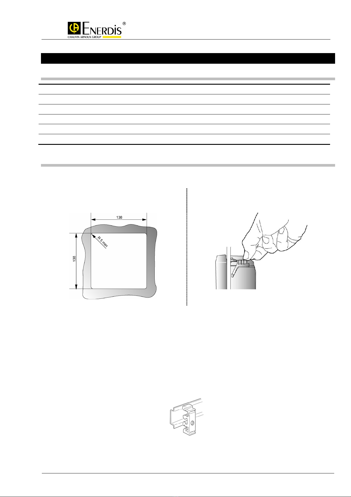
4.2 Version with display (Models 100/200/300)
Fixing can be by panel, DIN Rail, or inside the cabinet Proceed as follows:
For panel fixing:
•Make a cutout as shown below: •Insert the ENERIUM in the cutout from the front.
•Slide the four panel fasteners and push them until
they lock the ENERIUM into place.
Panel cutout dimensions Insert into the panel by lifting up the front and sliding it in
For DIN Rail and fixing inside the cabinet:
•DIN Rail fixing :
oInsert the ENERIUM in the cutout in the support fixture.
oFit the DIN Rail clips in the support fixture.
oConnect up the device.
oClip everything to the DIN Rail in the cabinet.
•Fixing inside the cabinet:
oInsert the ENERIUM in the cutout in the support fixture.
oConnect up the device.
oBolt everything into the cabinet.
Fixing clips

U
SER MANUAL
–
ENERIUM
100/200/300
MS
1
-
7352 ENERIUM100/200/300_ Ed0
4
User
Manual
Page
10
/
86
Support fixture for the DIN Rail and the inside of the cabinet
Overall dimensions in millimetres
144
144

U
SER MANUAL
–
ENERIUM
100/200/300
MS
1
-
7352 ENERIUM100/200/300_ Ed0
4
User
Manual
Page
11
/
86
4.3 Version without display (Models 110/210/310)
Fixing of these models can be by DIN Rail or inside the cabinet Proceed as follows:
•Clip the two supports (see below) on the DIN Rail
(spacing of 158 mm between bolts).
•Bolt the monitor on the two supports (for height
levels are possible).
Support for DIN Rail mounting
•To fix the monitor inside the cabinet, screw the unit
directly into the cabinet.
Overall dimensions in millimetres

U
SER MANUAL
–
ENERIUM
100/200/300
MS
1
-
7352 ENERIUM100/200/300_ Ed0
4
User
Manual
Page
12
/
86
5 F
RONT
V
IEW
This section shows which components are accessible from the front for each model.
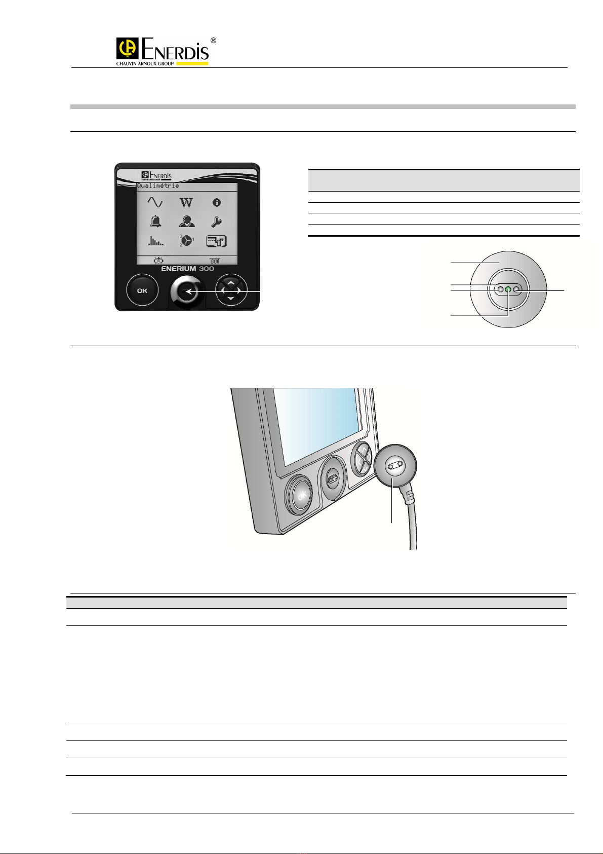
Front face of the ENERIUM 100, 200 or 300
5.1 Display screen
5.1.1 Introduction
The screen is a positive transmissive type LCD, has 128 lines of 160 pixels and is back-lit.
The backlight is activated by pressing one of the two buttons and switches off if no key press is
detected for 3 minutes
The contrast and brightness are adjustable via local or remote communication.
The main menu appears as follows:
Main menu
This screen enables:
•numerous measured and electrical quantities to be displayed
•Parameters to be displayed and changed
For the ENERIUM 100, the , and icons are not available.
For the ENERIUM 200, the icon is not available.
For the ENERIUM 300, all icons are available.
No.
Function
1 LCD screen
2 “OK” confirmation key
3 Front optical interface
4 Navigation keys

U
SER MANUAL
–
ENERIUM
100/200/300
MS
1
-
7352 ENERIUM100/200/300_ Ed0
4
User
Manual
Page
13
/
86
5.1.2 The upper part
The upper part shows the name of the screen being displayed.
Display of the input phase-neutral voltages
5.1.3 The central part
The central part gives an indication of the value of quantities displayed together with the corresponding
units.
The central part displays the measurements
5.1.4 The lower part
The lower part shows the states of the various icons
Icons on the lower part of the screen
Icon
Meaning
Flashing symbol, indicating that at least one global alarm is active
Fixed symbol, indicating a phase sequence error for voltage inputs
Flashing symbol, indicating that communication is in progress via the local or remote interfaces
Fixed symbol, indicating that automatic screen scrolling mode is active
Fixed symbol, indicating that the network is capacitive
Fixed symbol, indicating that the network is inductive
Fixed symbol, indicating that the network is a generator (not shown in receiver mode)
Quantities
Values
Units
MS
1
-
7352 ENERIUM100/200/300_ Ed0
5.2 Optical interface
5.2.1 Introduction
The optical interface consists of the following
5.2.2 Description
The optical interface allows parameters to be set, the downloading of measurements stored locally on
the ENERIUM to be sent to a PC, and the firmware to be updated, via the optical cable (accessory sold
separately, paragraph
3.2
5.2.3 Characteristics
Item
Protocol
Transmission format
Digital I/O
Indicator
Connector
U
SER MANUAL
–
ENERIUM
7352 ENERIUM100/200/300_ Ed0
4
User
Manual
The optical interface consists of the following
parts:
The optical interface allows parameters to be set, the downloading of measurements stored locally on
the ENERIUM to be sent to a PC, and the firmware to be updated, via the optical cable (accessory sold
3.2
Page 5).
Optical cable
Characteristics
ModBus in RTU mode
38400 baud fixed speed
1 start bit
8 data bits
No parity
1 stop bit
0 ms turnaround time
Responds to all slave addresses from 1 to 247
Optical (infrared) ensures bidirectional optical
transmission
Integral green metrology LED (pulse counting)
Optical connection with no electrical contact, paragraph
No.
Function
1 Metal washer
2 Locating device
3
Infrared communication transmitter and receiver
4
Green metrology LED and visual indicator
Optical
interface
Optical head
ENERIUM
100/200/300
Page
14
/
86
The optical interface allows parameters to be set, the downloading of measurements stored locally on
the ENERIUM to be sent to a PC, and the firmware to be updated, via the optical cable (accessory sold
transmission
Optical connection with no electrical contact, paragraph
3.2 on Page 5
Infrared communication transmitter and receiver
Green metrology LED and visual indicator
1
3
2
4
3
MS
1
-
7352 ENERIUM100/200/300_ Ed0
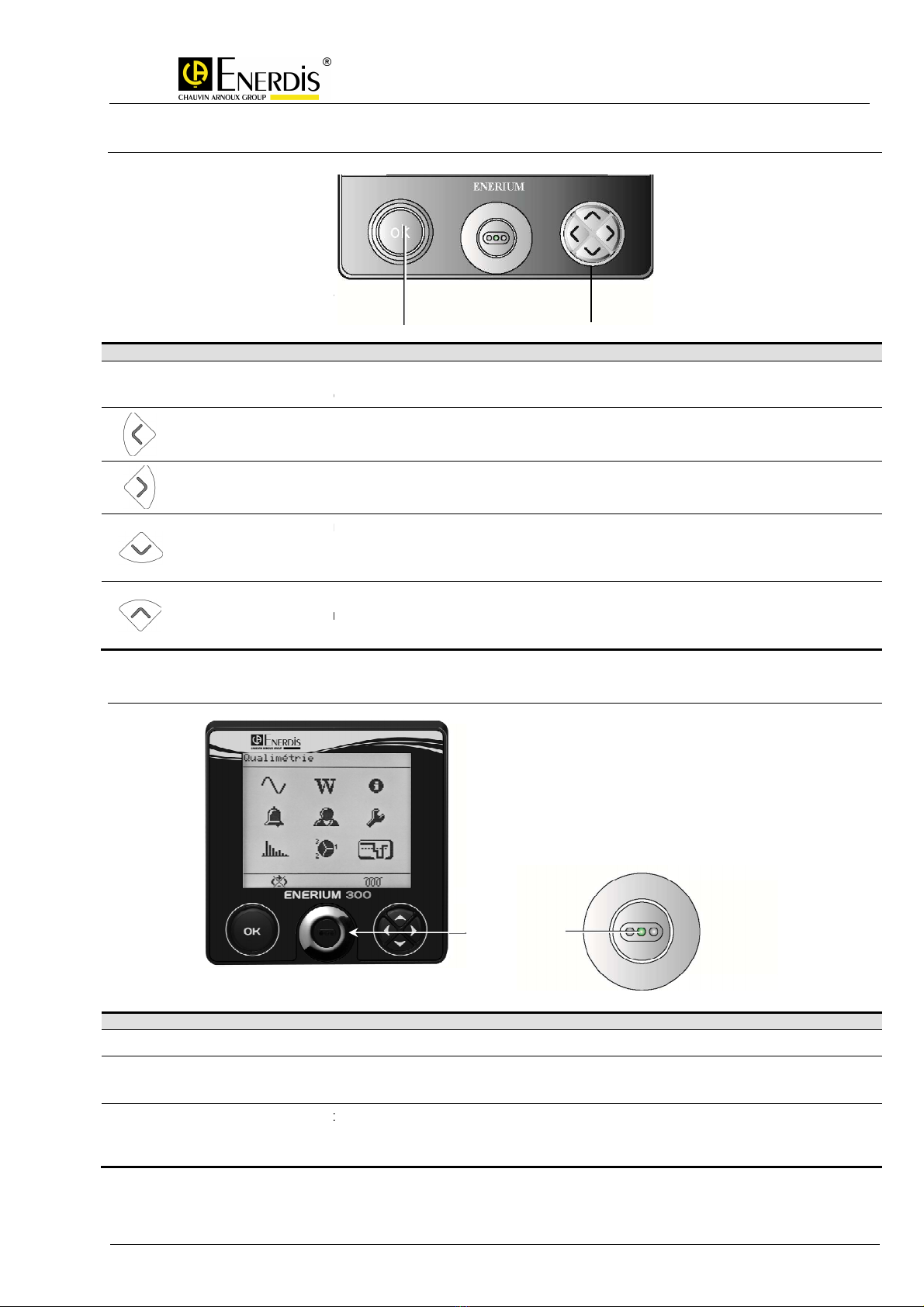
5.2.4 Keys
Key
Function
OK
Confirm selected choice
Entry to/Exit from edit mode
Move cursor left.
Return to preceding menu.
Move cursor right.
Menu: move cursor down
Parameter setting: decrement value
Lookup: go to next screen
Menu: move cursor up
Parameter setting: increment
Lookup: go to previous screen
5.2.5
Front status indicator
Indicator
Indication
Unlit ENERIUM
disconnected
Flashing
ENERIUM 100/200/300: Visual indication of the energy counter for the user or the optical
ENERIUM 110/210/310: No counter information available
Rapid flashing ENERIUM
faulty: Embedded software is faulty or requires an update
ENERIUM
awaiting embedded software to be loaded Communication is not possible and the screen is
faulty.
Confirmation
key
U
SER MANUAL
–
ENERIUM
7352 ENERIUM100/200/300_ Ed0
4
User
Manual
Confirm selected choice
or parameters
Entry to/Exit from edit mode
Return to preceding menu.
Menu: move cursor down
Parameter setting: decrement value
Lookup: go to next screen
Parameter setting: increment
value
Lookup: go to previous screen
Front status indicator
disconnected
ENERIUM 100/200/300: Visual indication of the energy counter for the user or the optical
ENERIUM 110/210/310: No counter information available
faulty: Embedded software is faulty or requires an update
awaiting embedded software to be loaded Communication is not possible and the screen is
Confirmation
Cursor keys
Status
indicator
ENERIUM
100/200/300
Page
15
/
86
ENERIUM 100/200/300: Visual indication of the energy counter for the user or the optical
cable.
awaiting embedded software to be loaded Communication is not possible and the screen is
Cursor keys

U
SER MANUAL
–
ENERIUM
100/200/300
MS
1
-
7352 ENERIUM100/200/300_ Ed0
4
User
Manual
Page
16
/
86
6 R
EAR
V
IEW
This section describes which components are accessible from the rear, for each model:
Rear view of the ENERIUM 100, 200 and 300
Rear view of the ENERIUM 110, 210 and 310
6.1 Measurement inputs
6.1.1 Voltage measurement inputs
6.1.1.1 Location
The voltage input terminals are labelled 9 to 13 on the rear right lower label.
6.1.1.2 Characteristics
Variables
Range
Nominal phase voltage 57.7/230 V
Nominal line voltage 100/400 V
Maximum line voltage 520V
Crest factor 2
Frequency 42.5 Hz to 69 Hz
24-hour overvoltage 800 V
Per-phase consumption 0.1 VA
Impedance 1 MΩ
No.
Function
1 Optional card connector block (digital or analog)
2 Rear optical interface
3 Current input terminals
4 Voltage input terminals
5 RS485 connector
6 Ethernet connector
7 Auxiliary source connector
Voltage inputs

U
SER MANUAL
–
ENERIUM
100/200/300
MS
1
-
7352 ENERIUM100/200/300_ Ed0
4
User
Manual
Page
17
/
86
Variables
Range
Non-removable terminals 5 screw terminals for rigid and flexible cables of between 4 and 6 mm²
Maximum torque: 0.8 Nm
6.1.2 Current measurement inputs
6.1.2.1 Location
The current input terminals are labelled 1 to 5 on the rear right lower label.
6.1.2.2 Characteristics
Variables
Range
Starting current 5 mA
Normal input current 5 A
Maximum input current 6.5 A
Crest factor 3
Frequency 42.5 Hz to 69 Hz
24-hour overcurrent 10A
Short-term overcurrent 250 A, over 1s
Per-phase consumption < 0.2 VA
Non-removable terminals 8 screw terminals for rigid and flexible cables of between 4 and 6 mm²
Maximum torque: 0.8 Nm
6.1.3 U and I protection
The use of fuses on the voltage inputs and a system for short-circuiting the input current is highly
recommended.
Current inputs
U
SER MANUAL
–
ENERIUM
100/200/300
MS
1
-
7352 ENERIUM100/200/300_ Ed0
4
User
Manual
Page
18
/
86
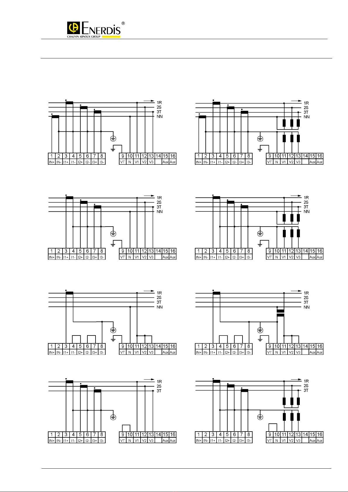
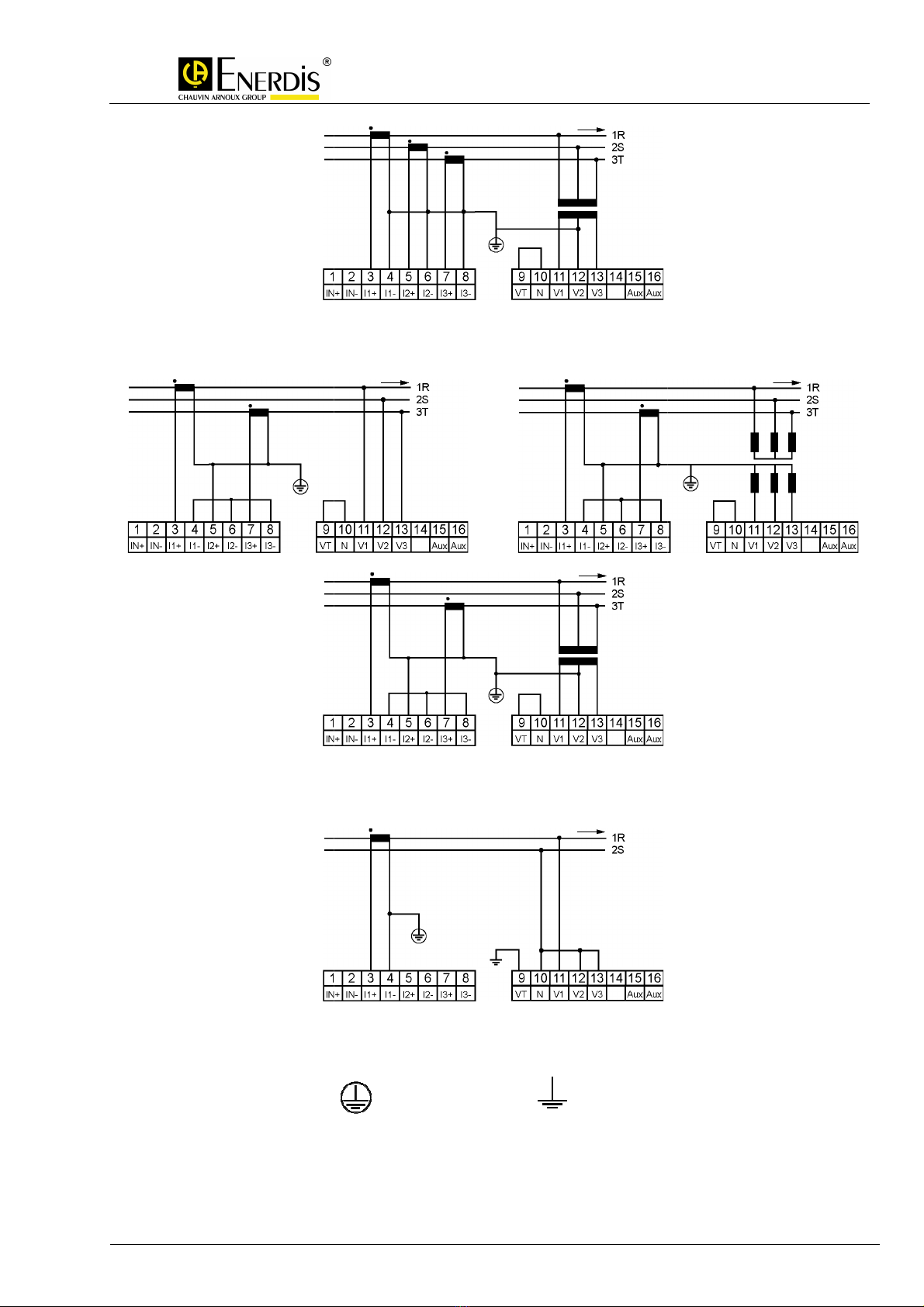
6.1.4 Recommended connection diagrams
The voltage and current inputs are connected according to the type of installation selected. The
recommended connection diagrams are as follows:
6.1.4.1 Unbalanced three-phase, 4 wire – 4 TC
Direct voltage input Voltage input 3 TP star
6.1.4.2 Balanced three phase, 4 wire – 3 TC
Direct voltage input Voltage input 3 TP star
6.1.4.3 Unbalanced three-phase, 4 wire – 1 TC
Direct voltage input Voltage input 1 TP
6.1.4.4 Unbalanced three-phase, 3 wire – 3 TC
Direct voltage input Voltage input 3 TP star
3
MS
1
-
7352 ENERIUM100/200/300_ Ed0
6.1.4.5 Unbalanced three-
phase, 3 wire
Direct voltage input
6.1.4.6 Unbalanced three-
phase, 2 wire
U
SER MANUAL
–
ENERIUM
7352 ENERIUM100/200/300_ Ed0
4
User
Manual
Voltage input 3 TP delta
phase, 3 wire
– 2 TC
Direct voltage input
Voltage input 3 TP star
Voltage input 3 TP delta
phase, 2 wire
– 1 TC
Direct voltage input
: Protective earth : Signal earth
ENERIUM
100/200/300
Page
19
/
86
Voltage input 3 TP star

U
SER MANUAL
–
ENERIUM
100/200/300
MS
1
-
7352 ENERIUM100/200/300_ Ed0
4
User
Manual
Page
20
/
86
6.2 Auxiliary source
6.2.1 Location
The auxiliary source terminals are labelled 15 to 16 on the rear right lower label.
Following a break in the auxiliary source, critical data are stored in non-volatile memory (paragraph
21.8).
6.2.2 Characteristics
Source
Characteristics
High Level supply (*) 80 Vac/dc to 265 Vac/dc
Frequency in the range 42.5 Hz to 69 Hz
Polarity-insensitive
Low Level supply (*) 19 Vdc to 58 Vdc
Consumption < 20 VA – 10 W
Non-removable terminals 2 screw terminals for rigid and flexible cables of between 4 and 8 mm²
Maximum torque: 0.8 Nm
(*) One or other. Power provided by the manufacturer
6.2.3 Connection
Ensure correct polarity if using the Low Level supply.
Connect the AC or DC power supply as paragraph 6.2.1.
A fuse or circuit breaker must be used.
Auxiliary source inputs
Other manuals for Enerium 100
1
This manual suits for next models
5
Table of contents
Other Enerdis Measuring Instrument manuals


Popular Measuring Instrument manuals by other brands

Umarex
Umarex Laserliner AutoCross-Laser 2 XP operating instructions

MONARCH INSTRUMENT
MONARCH INSTRUMENT PALM STROBE x instruction manual

BTI
BTI PROFILINE Disfix 50 manual

YOKOGAWA
YOKOGAWA PZ4000 user manual

CET
CET PMC-S963-E quick start guide

Dwyer Instruments
Dwyer Instruments 460 Operating instructions and parts list


