Energie SY250 Use and care manual

www.energie.pt 1
Assembly and User Manual
Thermodynamic Solar System
COMBI [6 | 12 | 16]
COMBI HT [12]
Energie Control Panel (SY250)
Directivas
2006/95/CE
2004/108/CE
R2V0 (23/03/2011)
EN
Review: 0
Version: 0
Date: 28/11/2014
CENTRAL HEATING
SWIMMING POOLS HEATING
LARGE VOLUMES HOT WATER
Energie Zuinig 2.0
Tel. 06 23605714

ASSEMBLY AND USER MANUAL
ENERGIE CONTROL PANEL (SY250)
2 www.energie.pt
INDEX
1. ENERGIE CONTROL PANEL (SY250)........................................................................... 3
2. CONNECTION BOX........................................................................................................ 3
1. Remove the four screws on the corners (A), see on the above connection box scheme....... 4
3. CONTROL PANEL.......................................................................................................... 4
3.1. Keys.................................................................................................................................. 5
3.2. LEDs................................................................................................................................. 5
3.3. Display.............................................................................................................................. 5
4. SYSTEM MENU.............................................................................................................. 6
5. ACCESS TO PARAMETERS / PROGRAMMING .......................................................... 8
6. MENU OF PROGRAMMING OF PARAMETERS.......................................................... 9
7. PROGRAMMING MENU “BUFFER 1” ........................................................................ 10
8. PROGRAMMING MENU “BUFFER 2 DHW” .............................................................. 11
9. INSTALLATION PLANT .............................................................................................. 11
10. “COUNTER” MENU...................................................................................................... 13
11. “TEST OUTPUTS” MENU............................................................................................. 14
12. LIST OF ERRORS.......................................................................................................... 14
13. OPERATION MODE...................................................................................................... 15
13.1. “OFF” Mode .............................................................................................................. 15
13.2. “CHECK-UP” Mode.................................................................................................. 15
13.3. “NORMAL” Mode .................................................................................................... 15
13.4. “SAFETY” MODE .................................................................................................... 16
14. APPLICATIONS OF THE BACKUP SYSTEM ............................................................. 17
14.1. System: ENERGIE and BACKUP.............................................................................. 17
14.2. System: ENERGIE and (ENERGIE + BACKUP) ...................................................... 18
14.3. System: (ENERGIE + BACKUP) and ENERGIE ...................................................... 18
ASSEMBLY AND USER MANUAL
ENERGIE CONTROL PANEL (SY250)
www.energie.pt 3
1. ENERGIE CONTROL PANEL (SY250)
The ENERGIE CONTROL PANEL SY250 is a control / command instrument for the ENERGIE thermodynamic
solar system.
It enables the setting of several functioning parameters of the equipment adapted to the system and user
operations.
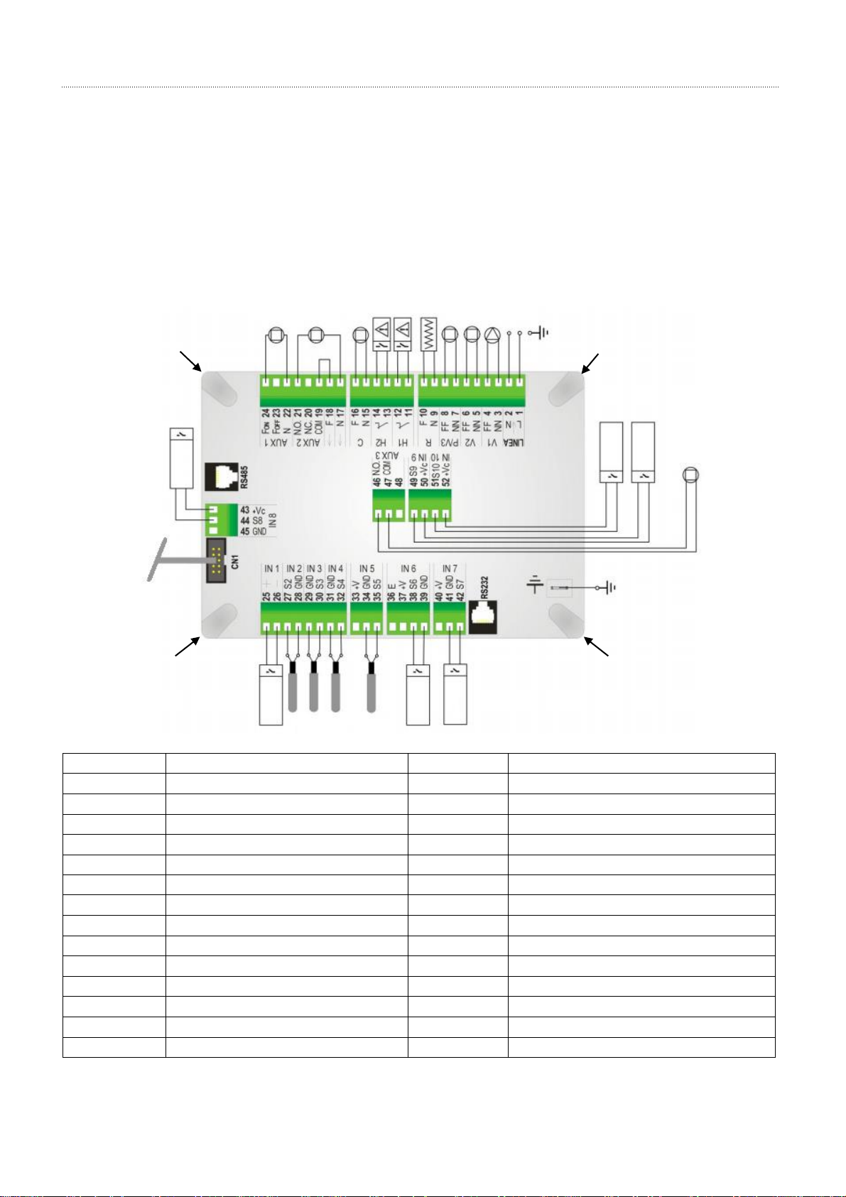
2. CONNECTION BOX
Connections
Function
Connections
Function
1-2
Power Supply 230VAC/ 50Hz
27-28
Probe 1 (return water temperature)
3-4
Pump 1
29-30
Probe 4 DHW
5-6
3 way valve (Central Heating circuit)
31-32
Probe 2 (gas)
7-8
3 way valve (DHW circuit)
33
Without connetion
9-10
Carter Resistance
34-35
Probe 3
11-12
Input TH (thermal)
36-37
Without connection.
13-14
Flow switch
38-39
Input LP (Low pressure switch)
15-16
Compressor
40
Without connection.
17-21
Back up 1 (support 1)
41-42
Input HP (High pressure switch)
18-19
Chante
43-44
Environment Thermostat
20
Without connection.
46-47
ON/OFF controller (V.E.E)
22-24
Back up 2 (support 2)
48
Without connection.
23
Without connection.
49-50
Digital input
25-26
External Thermostat
51-52
Controller input (V.E.E)
A
A
A
A

ASSEMBLY AND USER MANUAL
ENERGIE CONTROL PANEL (SY250)
4 www.energie.pt
ELECTRONIC BOARD BATTERY
1. Remove the four screws on the corners (A), see on the above connection box scheme
2. Open the connection box
3. Check the battery on the electronic board
3. CONTROL PANEL
The control panel is the interface between equipment and user. It enables one to check on the system’s
functioning and consult / modify its parameters.
BATTERY
ASSEMBLY AND USER MANUAL
ENERGIE CONTROL PANEL (SY250)
www.energie.pt 5
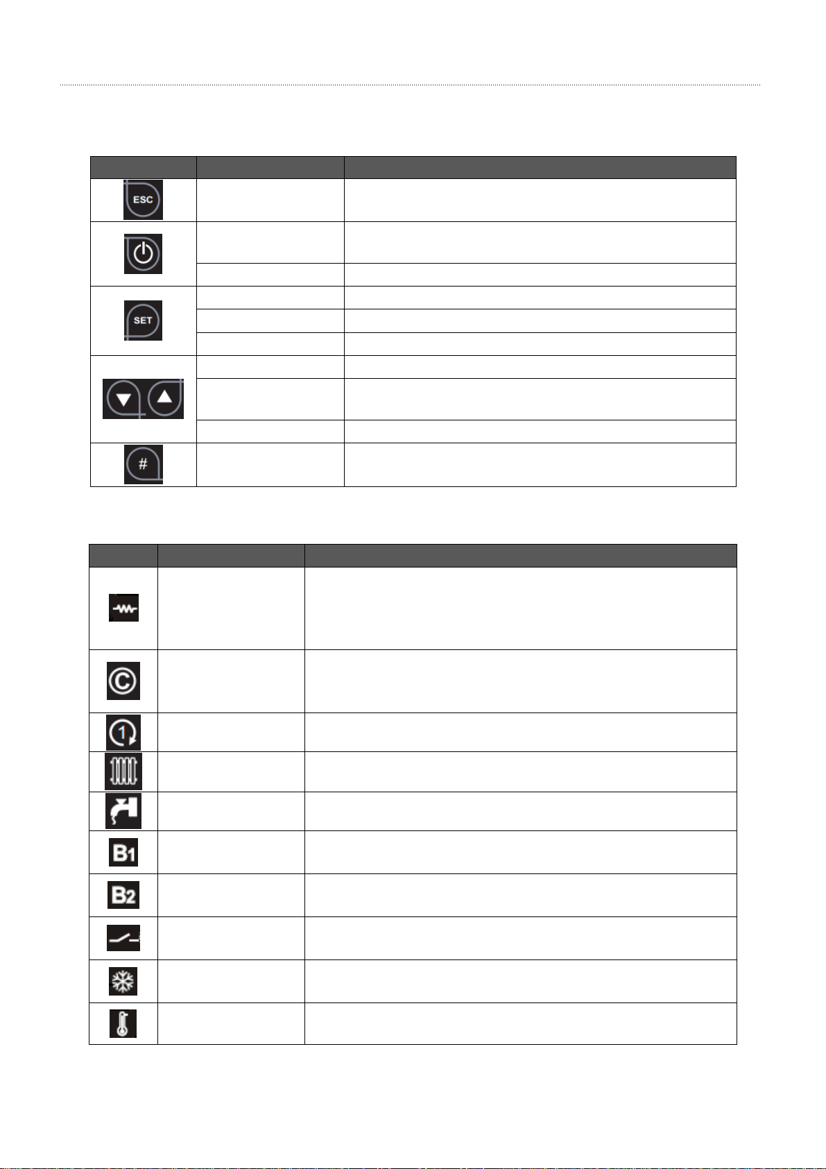
3.1. Keys
KEY
FUNCTION
DESCRIPTION
RETURN
ESC function enables leaving a menu or sub-menu.
UNBLOCK
When the system is frozen press the key for 3 seconds until
you hear the sound signal.
ON/OFF
Switch on/ switch off the equipment (press for 3 seconds).
MENU
Open menu and Sub-Menu.
MODIFY
Open the option to modify parameters.
SET
Save data.
CHANGE VALUES
It enables setting / modifying the values for the parameters.
RUN MENU / SUB-
MENU
Function for running menus and sub-menus.
DISPLAY
Function for consulting values of parameters.
ON / OFF
RESISTANCE
Pressing the key enables switching on and off the resistance.
3.2. LEDs
LED
FUNCTION
DESCRIPTION
RESISTANCE
LED ON: On
LED OFF: Off
LED blinks: after pressing the key P5, the resistance may switch on
if the conditions are right.
COMPRESSOR
LED ON: On
LED OFF: Off
LED blinks: Time-setting (timer T06)
PUMP 1
LED ON: Pump is working
3 WAY VALVE
LED ON: Central Heating circuit
3 WAY VALVE
LED ON: DHW circuit
BACKUP 1
LED ON: Backup system 1 is on (CH)
LED blinks: Time-setting (timer T02)
BACKUP 2
LED ON: Backup system 2 is on (DHW).
LED blinks: Time-setting (timer T03)
INPUT V
LED ON: Closed contact
LED OFF: Open contact
EXTERNAL
THERMOSTAT
LED ON: Closed contact
LED OFF: Open contact
ENVIRONMENT
THERMOSTAT
LED ON: Temperature of the environment is below the set value
(closed contact)
3.3. Display

ASSEMBLY AND USER MANUAL
ENERGIE CONTROL PANEL (SY250)
6 www.energie.pt
The Electrónico will have the following configuration as a display background, which enables the simultaneous
visualization of different parameters:
Display
Examples
Description
S1
Probe Temperature 1
S2
Probe Temperature 2
Chrono programming is active
4. SYSTEM MENU
This chapter will describe the menus that the user can access when he intends to carry out a modification of the
configuration of the display or equipment. The menu is divided in the following items:
Chrono Menu
Date and Time Menu
Language Menu
Keyboard Menu
System Menu
CHRONO MENU: Hourly programming of equipment according to the chosen mode.
Code of ERROR
System Status
Date and Time
CHRONO
Temperature Probes
de Temp.
LEDs

ASSEMBLY AND USER MANUAL
ENERGIE CONTROL PANEL (SY250)
www.energie.pt 7
CHRONO PROGRAMMING
Daily program
For each day there are 3 possible switch on and switch off times.
Weekly program
Using this program the 3 switch on and switch off times are the same for all days of the week.
Week-end program
It is possible to select the periods “Monday-Friday” or “Saturday-Sunday”. For each period there are 3 switch on
and switch off times.
NOTE: After the Chrono programming to switch on the system by Chrono it is necessary to enable the
desired mode (Daily, Weekly or Week-end) from Modality menu.
The three programs modalities are saved separately: if you set for example the daily mode, the others
mode aren’t modified.
Date and Time Menu: Change time and date of system.
Language Menu: Change language of display.

ASSEMBLY AND USER MANUAL
ENERGIE CONTROL PANEL (SY250)
8 www.energie.pt
Keyboard Menu: It enables the user to test the connection of display and controller; update the information of the
display when placed in a different controller; set contrast of display; set brightness of display.
System Menu: Change or consult system parameters.
5. ACCESS TO PARAMETERS / PROGRAMMING
In order to gain access to menus, submenus and consult / change system parameters, the user must insert a
system access password that is set by default to “0000”.
In order to introduce the access password simply press to show the first digit, press to change
the digit and select . Repeat the procedure for each digit of the password.

ASSEMBLY AND USER MANUAL
ENERGIE CONTROL PANEL (SY250)
www.energie.pt 9
If the introduced password is correct the following information will be on display.
Display
Function
Description
Installation Plant
Set / consult system parameters
Set / consult parameters for Dep. of Inertia (Probe 3)
Set / consult parameters for AQS Dep. (Probe 4)
Counters
Test outputs
Restore factory parameters
To run through, change or consult the list of parameters, you must use the following keys:
Display
Function
Description
Gain access to selected parameter
Run through parameters
Save value for parameter and move to the next one
Cancel value for parameter or leave menu
6. MENU OF PROGRAMMING OF PARAMETERS
Menu in which you can display / modify the values for temperatures of probe 1, probe 2, circulation pumps,
timers, etc.
Code
Type
Name
Min(ºC)
Max(ºC)
Factory parameter
THS101
S1
Return Minimum Temperature
0
60
2 °C
THS102
S1
Return Maximum Temperature
10
70
45 °C
HYS102
S1
THS102 Temperature Gradient
1
10
5 °C
THS103
S1
Alarm Temperature
10
75
55 °C
THS201
S2
Alarm Temperature (gas)
10
80
60 °C
T01
Timer
Time Min Compressor OFF
1
2000 hours
12 hours
T06
Timer
Compressor Timer
0
20 min
1 min
T07
Timer
Delay in compressor start-up
0
60 min
20 min
P08
Conf.
DHW priority circuit
0
1
1
P09
Conf.
Set reading for input V
0
1
0
ASSEMBLY AND USER MANUAL
ENERGIE CONTROL PANEL (SY250)
10 www.energie.pt
Note 1: T01 → Timer is activated every time the compressor comes to a halt. When the timer exceeds the set
time, and the compressor starts again, it will activate T07 and connect the carter resistance.
The value for T07 MUST NEVER be below 20 min.
Note 2: Sequence of circuits (priority)
P08 = 0 → Simultaneous circuits central heating and DHW.
P08 = 1 → DHW priority circuit.
The P08 value must never be changed to 0.
Note 3: Analog input configuration (S4 probe, pin 29-30)
P09 = 0 → Input V is set to “read” a temperature probe (Probe 4).
P09 = 1 → Input V is set to “read” a contact.
The P09 value must never be changed to 1.
7. PROGRAMMING MENU “BUFFER 1”
Code
Type
Name
Min(°C)
Max(°C)
Factory
parameter
T02
Timer
Delay Backup 1
1
60
10 min
THS301
S3
Minimum Temperature
10
50
10 °C
HYS301
S3
THS301 Temperature Gradient
1
10
1 °C
THS302
S3
Maximum Temperature
20
65
45 °C
HYS302
S3
THS302 Temperature Gradient
1
10
3 °C
THS303
S3
Alarm Temperature
10
80
65 °C
HYS303
S3
THS303 Temperature Gradient
1
10
3 °C
THS304
S3
Minimum Temperature Backup 1
10
60
10 °C
THS305
S3
Maximum temperature Backup 1
20
80
47 °C
HYS305
S3
THS305 Temperature Gradient
1
50
5 °C
THS306
S3
Minimum Temperature 2
10
50
10 °C
HYS306
S3
THS306 Temperature Gradient
1
10
1 °C
BUFFER 1 MANAGEMENT
The Back Up Output has the following functioning:
System State
Output state
Control
OFF
OFF
---
Check Up
Normal
Safety
ON
Probe S3 temperature<THS303 Thermostat and
THS304 Thermostat<Probe S3 temperature <THS305
Thermostat and Input T closed and Input Flowswitch closed
and External Thermostat closed
OFF
Off other cases
When the temperature decreases is considered the lowest between Thermostat THS302 and Thermostat THS304
to disable the output. The Back Up starts with a delay equal to the parameter T02.

ASSEMBLY AND USER MANUAL
ENERGIE CONTROL PANEL (SY250)
www.energie.pt 11
8. PROGRAMMING MENU “BUFFER 2 DHW”
Code
Type
Name
Min(°C)
Max(°C)
Factory
parameter
T03
Timer
Delay Backup 2
1
60
1 min
THS402
S4
Maximum Temperature
20
65
20 °C
HYS402
S4
THS402 Temperature Gradient
1
10
2 °C
THS403
S4
Alarm Temperature
10
80
60 °C
HYS403
S4
THS403 Temperature Gradient
1
10
2 °C
THS404
S4
Minimum Temperature Backup 2
10
60
10 °C
THS405
S4
Maximum Temperature Backup 2
20
80
50 °C
HYS405
S4
THS405 Temperature Gradient
1
50
5 °C
THS406
S4
DHW Temperature
20
60
50 °C
HYS406
S4
THS406 Temperature Gradient
1
10
3 °C
BUFFER 2 MANAGEMENT
The Back Up Output has the following functioning:
System State
Output state
Control
OFF
OFF
---
Check Up
Normal
Safety
ON
Probe S4 temperature<THS403 Thermostat and THS404
Thermostat<Probe S4 temperature<THS405 Thermostat
and External Thermostat closed
OFF
Off other cases
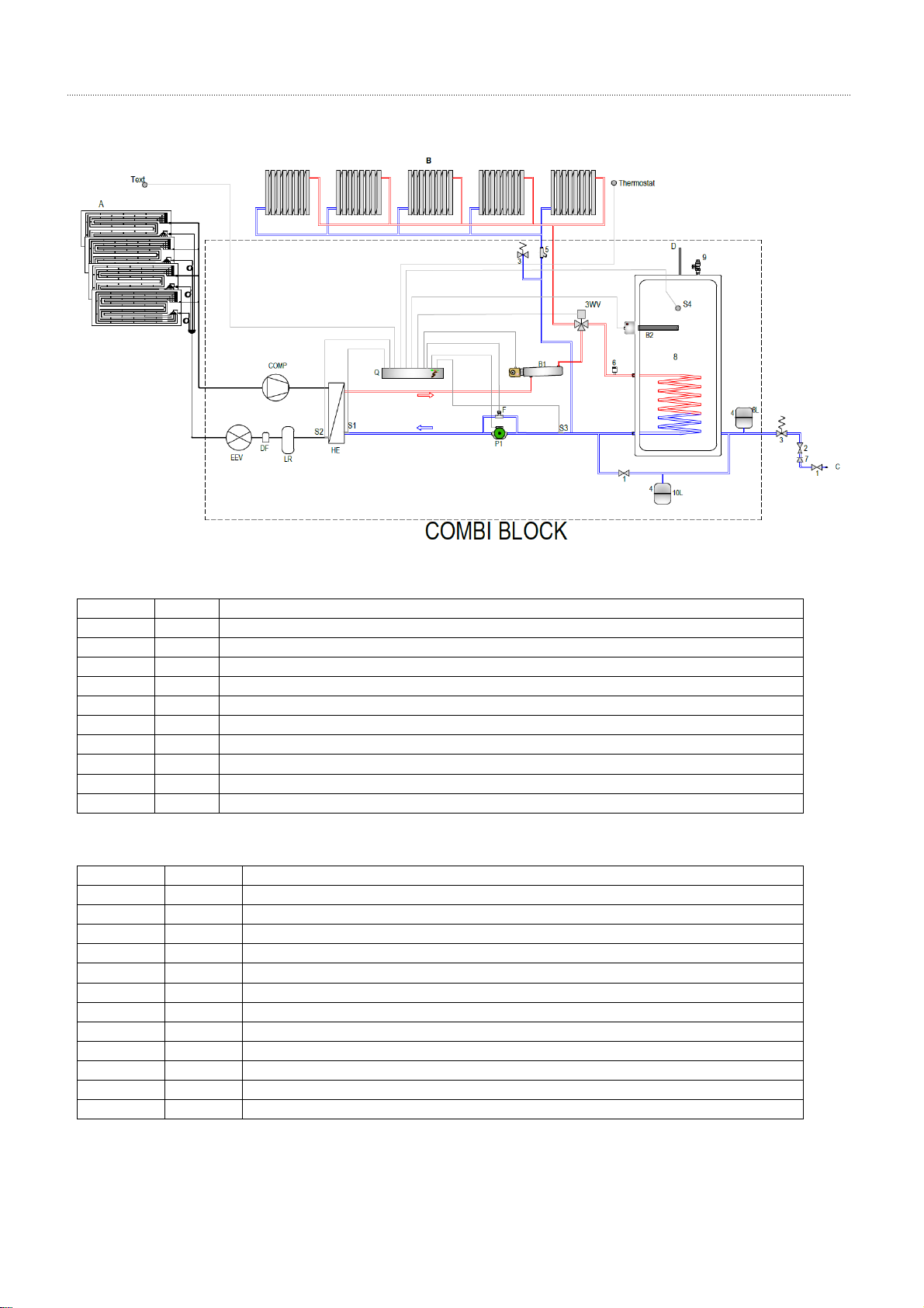
9. INSTALLATION PLANT
Representative plant [PLANT 12]
Inputs (Probes): S1, S2, S3 and S4
Outputs: Pump P1, 3 way valve (P1 and P2),Buffer B1 and Buffer B2
Note: B1 and B2 will not start unless the external thermostat is closed (LED ON).
The plant 12 must never be changed. Otherwise, there is the danger of injury and guaranty loss.
ASSEMBLY AND USER MANUAL
ENERGIE CONTROL PANEL (SY250)
12 www.energie.pt
Plant
Parameters:
Code
Type
Description
THS101
S1
Minimum Temperature (water return)
THS102
S1
Maximum Temperature (water return)
HYS102
S1
THS102 Temperature Gradient
THS103
S1
Alarm Temperature (water return)
THS201
S2
Alarm Temperature (Gas)
T01
Timer
Time Min Compressor OFF
T06
Timer
Timer (delay in the compressor’s start-up)
T07
Timer
Timer (delay in the compressor’s start-up, carter resistance is ON)
P08
Conf.
Priorities of circuits
P09
Conf.
Set reading for input V
Buffer 1:
Code
Type
Description
T02
Timer
Delay in the start-up Backup 1
THS301
S3
Start-up Minimum Temperature P2
HYS301
S3
THS301 Temperature Gradient
THS302
S3
Maximum Temperature for STOP COMBI System.
HYS302
S3
THS302 Temperature Gradient
THS303
S3
Alarm Temperature
HYS303
S3
THS303 Temperature Gradient
THS304
S3
Start-up minimum temperature Backup 1
THS305
S3
Maximum Temperature for STOP Backup 1
HYS305
S3
THS305 Temperature Gradient
THS306
S3
Start-up Minimum Temperature P3
HYS306
S3
THS306 Temperature Gradient

ASSEMBLY AND USER MANUAL
ENERGIE CONTROL PANEL (SY250)
www.energie.pt 13
Buffer 2:
Code
Type
Description
T03
Timer
Delay in the start-up Backup 2
THS404
S4
Start-up Minimum Temperature Backup 2
THS405
S4
Maximum Temperature for STOP Backup 2
HYS405
S4
THS405 Temperature Gradient
THS406
S4
AQS Temperature (Set point)
HYS406
S4
THS406 Temperature Gradient
10. “COUNTER” MENU
The counter menu will be divided into 3 submenus:
Compressor.
Reset.
List of Errors.
Compressor: Shows the number of hours of operation of the compressor.
Reset: Erases the record of all alarms and sets the counters to zero. In order to erase all records and set the
counters to zero, it is necessary to introduce a password (Manufacturer).
List of Errors: Shows a list of the last 5 errors in the following way:
Note: If the contact for the fluxostat is open, the system will not register any other type of error.
ASSEMBLY AND USER MANUAL
ENERGIE CONTROL PANEL (SY250)
14 www.energie.pt
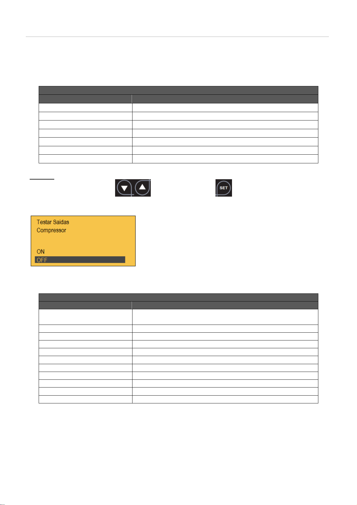
11. “TEST OUTPUTS” MENU
In order to test the outputs the system must be switched off. The test for each output is carried out individually.
Display
Submenu
Description
Compressor
Switches on the Compressor
Pump 1
Switches on the Circulation Pump 1
3 way valve (P2)
Switches on the Central Heating circuit
3 way valve (P3)
Switches on the DHW circuit
Resistance
Switches on the Carter Resistance
Backup 1
Switches on the Backup System 1
Backup 2
Switches on the Backup System 2 (DHW)
Example
Select icon “ON” with the keys and next press the key to switch on the compressor. Carry
out the process in reverse to switch off the compressor.
12. LIST OF ERRORS
Display
Error
Description
Er01 –Flow
(during check up is not an error)
Contact of flow switch is open (absence of flow or insufficient flow)
Er02 –TN
Safety Thermostat
Er03 –LP
Circuit Low Pressure Alarm
Er04 –HP
Circuit High Pressure Alarm
Er05 –TS1
Temperature Probe Alarm S1
Er05 –TS2
Temperature Probe Alarm S2
Er06 –TS3
Temperature Probe Alarm S3
Er07 –TS4
Temperature Probe Alarm S4
Er08 –RTC
Damaged Internal Clock or battery is discharged or weak
Er09 –TL
Probes S1, S2, S3 or S4 are damaged
Er11 –EVD
Electronic expansion valve controller
ASSEMBLY AND USER MANUAL
ENERGIE CONTROL PANEL (SY250)
www.energie.pt 15
13. OPERATION MODE
The electronic ENERGIE (SY250) possesses 4 operation modes. In this chapter, the operation modes for inputs’
control and outputs’ control will be explained.
Modes:
OFF
CHECK-UP
NORMAL
SAFETY
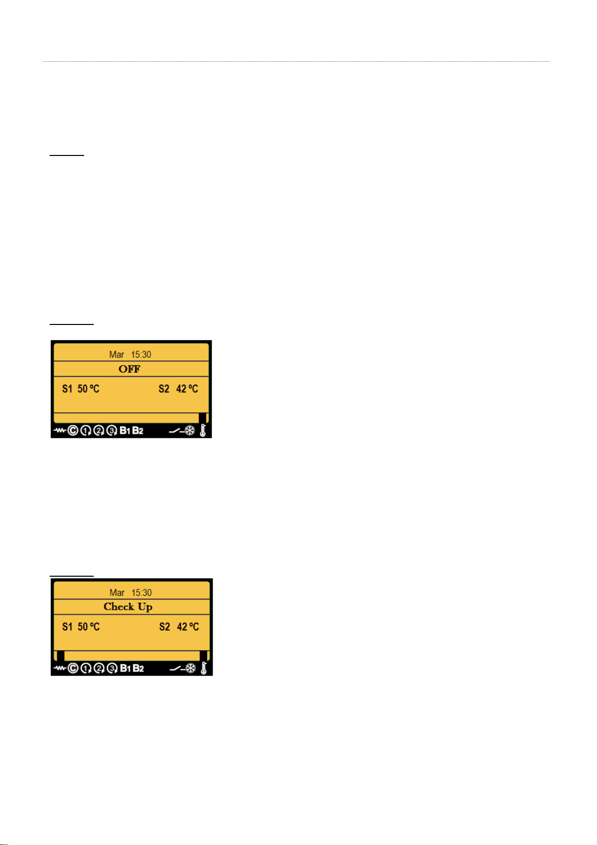
13.1. “OFF” Mode
In the off mode (OFF) the screen shows:
- Display OFF (only if you visualize the clock and the values for the probes)
- Compressor, Pump 1, Carter Resistance, Back Up –OFF (everything switched off).
Example:
13.2. “CHECK-UP” Mode
In the mode for time-setting (check-up), the electronic will review every connection, checking the connection of
the probes; the screen shows:
- Display Check Up.
- Carter Resistance and Environment Thermostat are “ON”.
- Compressor, Pump 1, etc., everything “OFF”.
- Etc.
Example:
13.3. “NORMAL” Mode
In the (normal) operating mode the control panel shows the following information, according to the typology of
installation employed:
- Compressor is “ON”
- Circulation Pump 1 is “ON”

ASSEMBLY AND USER MANUAL
ENERGIE CONTROL PANEL (SY250)
16 www.energie.pt
- Environment Thermostat is “ON”
- Etc.
Example:
13.4. “SAFETY” MODE
In the safety mode, the electrónico will protect the equipment from potential malfunctions such as:
- Safety thermal (TH)
- Low pressure (LP)
- High Pressure (HP)
- Damaged Probe or not properly connected (TL)
- Etc.
Example:

ASSEMBLY AND USER MANUAL
ENERGIE CONTROL PANEL (SY250)
www.energie.pt 17
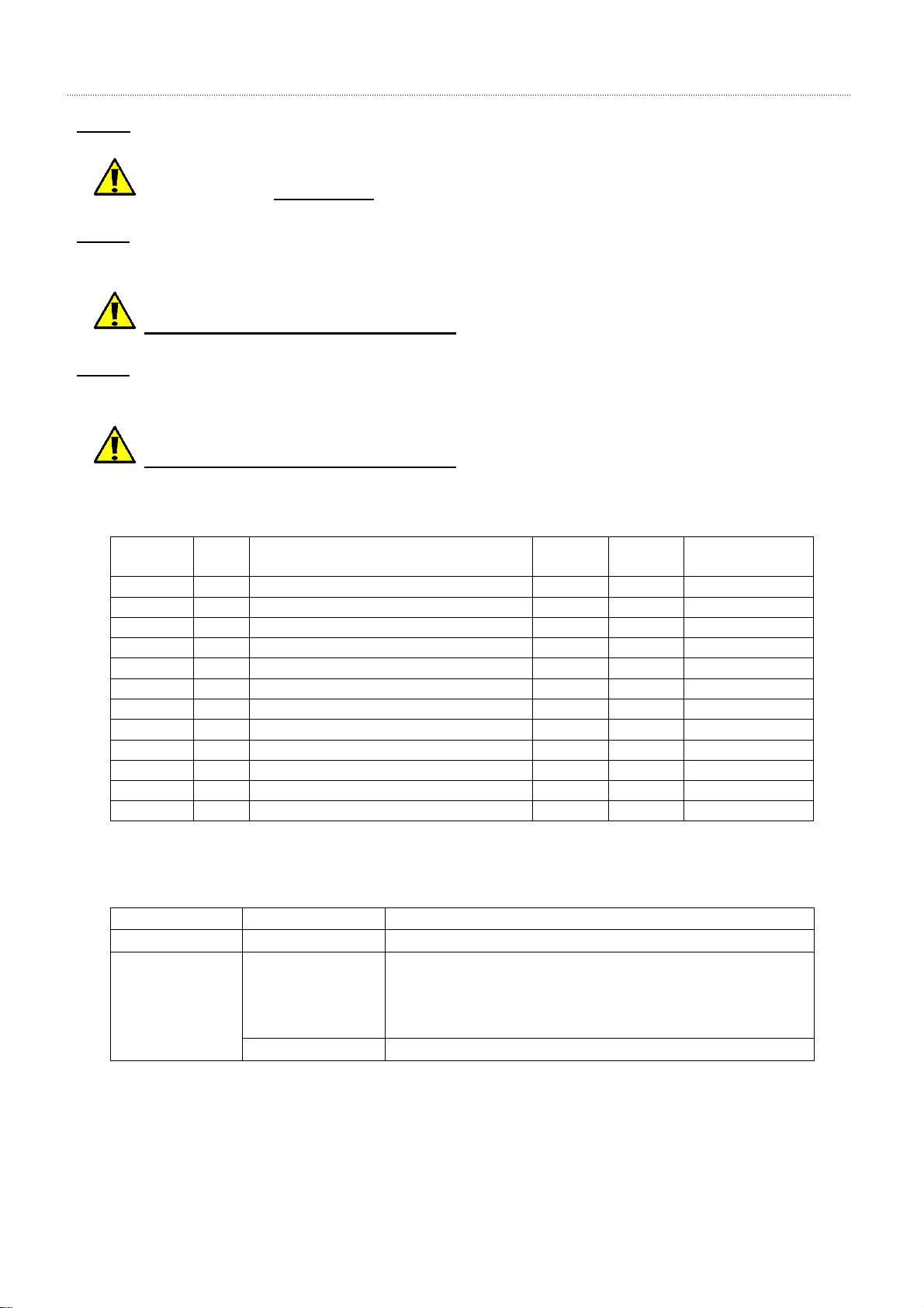
14. APPLICATIONS OF THE BACKUP SYSTEM
The Backup System(s) can engage simultaneously with the ENERGIE System in the following situations:
ENERGIE System and BACKUP. To raise the water temperature above 55 °C.
ENERGIE System and (ENERGIE + BACKUP). Low external temperatures.
(ENERGIE + BACKUP)and ENERGIE System. Start with “Backup” support.
Note: In every situation described above the Backups 1 and 2 will not engage unless the external thermostat is
closed.
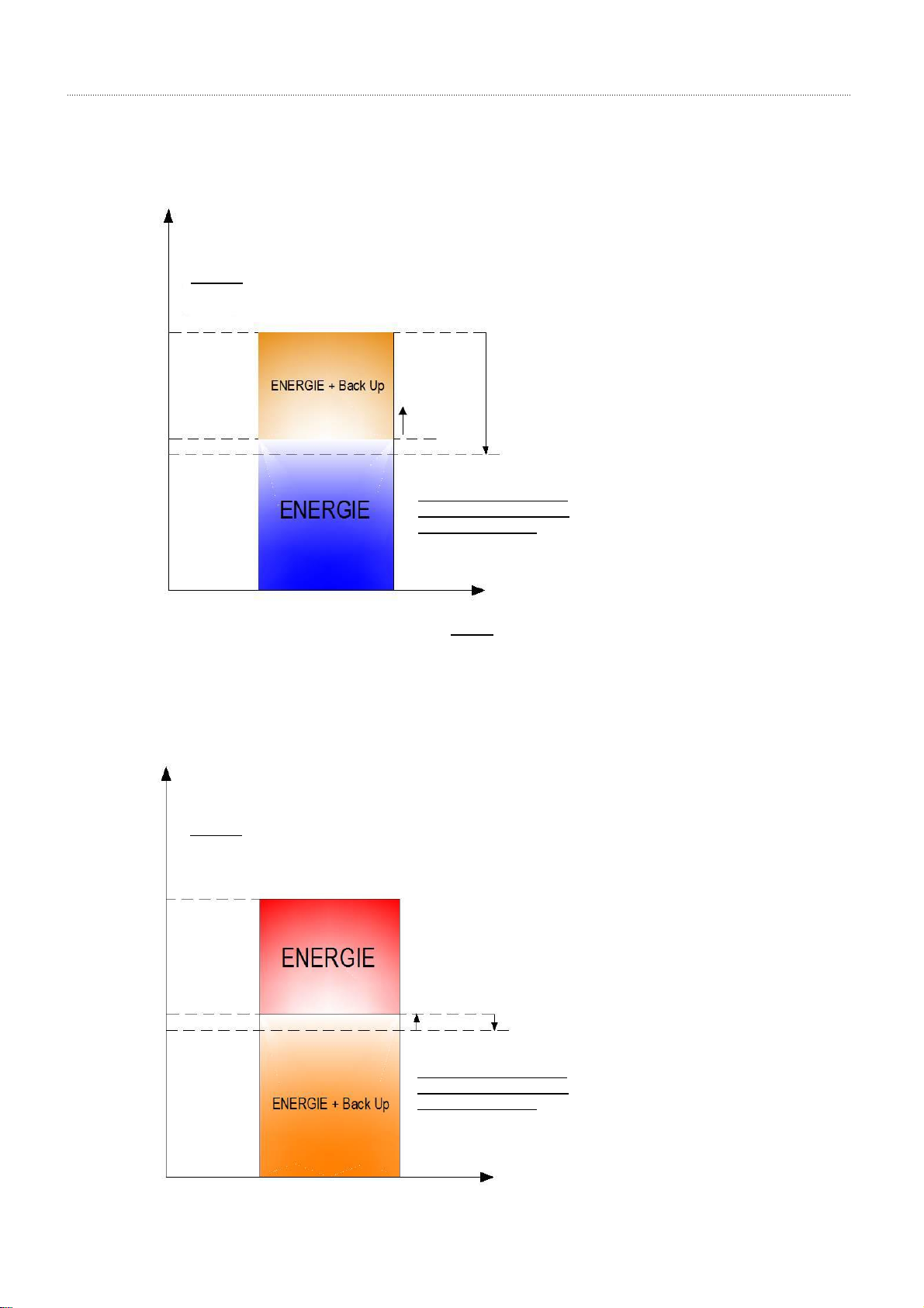
14.1. System: ENERGIE and BACKUP
The Parameters that should be adopted in the configuration of the Backup System are the following:
ENERGIE and BACKUP
ENERGIE and (ENERGIE + BACKUP)
(ENERGIE + BACKUP) and ENERGIE
Temperature > 55 °C
Low external temperatures
Start with Backup
Condition:
Back up only works if the outdoor
thermostat contact is closed
Condition:
Back up only works if the outdoor
thermostat contact is closed
Condition:
Back up only works if the outdoor
thermostat contact is closed
Timer
Timer
Timer
Temperature (0C)
Temperature (0C)
Temperature (0C)
Condition:
Back up only works if the outdoor
thermostat contact is closed
After reaching 65 0C, back up
only works at 43 0C (THS305-
HYS305) + Timer (T02)
Timer (T02)
HYS305=220C
430(650- 22 0)
THS305 = 65 0C
THS302 = 50 0C
THS304 = 48 0C
Probe temperature (0C)
Note: The diferential HYS305 should be higher than THS305 –THS304
ASSEMBLY AND USER MANUAL
ENERGIE CONTROL PANEL (SY250)
18 www.energie.pt
14.2. System: ENERGIE and (ENERGIE + BACKUP)
The Parameters that should be adopted in the configuration of the Backup System are the following:
14.3. System: (ENERGIE + BACKUP) and ENERGIE
The Parameters that should be adopted in the configuration of the Backup System are the following:
Condition:
Back up only works if the outdoor
thermostat contact is closed
HYS305=220C
Timer (T02)
280(450- 17 0)
After reaching 45 0C, back up
only works at 28 0C (THS305-
HYS305) + Timer (T02)
Note: The diferential HYS305 should be higher than THS305 –THS304
THS305 = 45 0C
THS302 = 45 0C
THS304 = 38 0C
Probe temperature (0C)
Timer (T02)
HYS305=50C
After reaching 45 0C, back up
only works at 25 0C (THS305-
HYS305) + Timer (T02)
Condition:
Back up only works if the outdoor
thermostat contact is closed
THS302 = 45 0C
THS305 = 30 0C
Probe temperature (0C)

Table of contents


