Energy Recovery Pressure Exchanger 4S Series Instruction manual

Energy Recovery, Inc. 1 ERI Document Number 80022-01-04
ENERGY RECOVERY
,
INC.
INSTALLATION, OPERATION, & MAINTENANCE
MANUAL
ERI DOCUMENT NUMBER 80022-01 REVISION 4
ERI™
4S Series Pressure Exchanger™
Energy Recovery Device
Energy Recovery, Inc.
1908 Doolittle Drive, San Leandro, CA 94577 USA
Tel: +1 510 483 7370 / Fax: +1 510 483 7371
© Energy Recovery, Inc., 2004-6

4S-SERIES PRESSURE EXCHANGER ENERGY RECOVERY DEVICES
Energy Recovery, Inc. 2 ERI Document Number 80022-01-04
INSTALLATION, OPERATION, & MAINTENANCE MANUAL
ERI 4S SERIES PRESSURE EXCHANGER
TABLE OF CONTENTS
1.0 INTRODUCTION 3
2.0 SAFETY 3
3.0 QUALITY & ARRIVAL INSPECTION 4
4.0 DESIGN CONSIDERATIONS 4
4.1 HOW THE PX ENERGY RECOVERY DEVICE WORKS 4
4.2 PX ENERGY RECOVERY DEVICES IN SWRO SYSTEMS 5
4.3 PX ENERGY RECOVERY DEVICE PERFORMANCE 7
4.4 THE PX BOOSTER PUMP 7
4.5 CONTROL OF FEED FLOW,PRESSURE AND PERMEATE WATER QUALITY 7
4.6 FRESH WATER FLUSHING 8
4.7 DEBRIS AND INITIAL FLUSHING 8
4.8 HIGH PRESSURE REMAINS AFTER SHUTDOWN 9
4.9 LOW PRESSURE ISOLATION AND OVER PRESSURIZATION 9
4.10 MULTIPLE PX UNIT MANIFOLD DESIGN 9
5.0 INSTALLATION 10
6.0 OPERATION 10
6.1 SYSTEM PERFORMANCE SPECIFICATIONS,PRECAUTIONS AND CONDITIONS 10
6.2 START AND STOP PROCEDURES 12
6.2.1 SYSTEM START UP SEQUENCE 12
6.2.2 SHORT TERM (1-3 DAYS)SYSTEM SHUT DOWN SEQUENCE 13
6.2.3 MEDIUM TERM (4-14 DAYS)SYSTEM SHUT DOWN SEQUENCE 13
6.2.4 LONG TERM (OVER 2WEEKS)SYSTEM SHUT DOWN SEQUENCE 13
6.2.5 MEMBRANE CLEANING 14
6.3 FLOW CONTROL AND BALANCING THE SYSTEM 14
6.3.1 HIGH PRESSURE FLOW CONTROL 14
6.3.2 LOW PRESSURE FLOW CONTROL 14
6.3.3 BALANCING THE PX ENERGY RECOVERY DEVICE 15
6.3.4 VERIFICATION OF PX ENERGY RECOVERY DEVICE FLOW BALANCE 15
6.3.5 MEASUREMENT OF PX DEVICE LUBRICATION FLOW RATE 16
7.0 SPARE PARTS AND TOOL KITS 16
8.0 MAINTENANCE 16
8.1 DISASSEMBLY PROCEDURE 17
8.2 ASSEMBLY PROCEDURE 20
9.0 TROUBLE SHOOTING 27
10.0 FIELD COMMISSIONING 30
11.0 REVISION LOG 30
12.0 LIMITED PRIMARY PRODUCT WARRANTY 31
13.0 DRAWINGS AND DATA 33

4S-SERIES PRESSURE EXCHANGER ENERGY RECOVERY DEVICES
Energy Recovery, Inc. 3 ERI Document Number 80022-01-04
1.0 INTRODUCTION
This manual contains instructions for the installation, operation, and maintenance of the Energy
Recovery, Inc.™™ERI™4S Series PX Pressure Exchanger™energy recovery device in sea
water reverse osmosis (SWRO) systems. This information is provided to ensure the long life and
safe operation of your PX™energy recovery device. Please read this manual thoroughly before
installation and operation and keep it for future reference. The instructions in this manual are
intended for personnel with general training and experience in the operation and maintenance of
fluid handling systems.
2.0 SAFETY
The PX Pressure Exchanger energy recovery device is designed to provide safe and reliable
service. However, it is both a pressure vessel and a piece of rotating industrial machinery.
Therefore, operations and maintenance personnel must exercise good judgment and proper safety
practices to avoid damage to the equipment, to avoid damage to surrounding areas, and to
prevent injury. It must be understood that the information contained in this manual does not
relieve operation and maintenance personnel of the responsibility of exercising normal good
judgment in the operation and care of this product and its components. The safety officer at the
location where this equipment is installed must establish a safety program based on a thorough
analysis of local industrial hazards. Proper installation and care of shutdown devices and over-
pressure and over-flow protection equipment must be an essential part of any such program. In
general, all personnel must be guided by all the basic rules of safety associated with high-
pressure equipment and processes. Operation under conditions outside of those stated in Table 6-
1 can result in damage to the ERI device and must be avoided.
The flags shown and defined below are used throughout this manual. They should be given
special attention when they appear in the text.
™Energy Recovery, Inc., ERI, PX, Pressure Exchanger, and PX Pressure Exchanger are trademarks of
Energy Recovery, Inc.
Energy Recovery, Inc. will not be liable for any project delay, damage or injury
caused by the failure to comply with the procedures in this manual. This product
must never be operated at flow rates, pressures or temperatures outside of those
stated in Table 6-1, or used with liquids not approved by Energy Recovery, Inc.
NOTE
These flags denote items that, if not strictly observed, can
result in serious injury to personnel.
These flags denote items that, if not strictly observed, can
result in damage or destruction to equipment.
These flags denote highlighted items.
NOTE
CAUTION

4S-SERIES PRESSURE EXCHANGER ENERGY RECOVERY DEVICES
Energy Recovery, Inc. 4 ERI Document Number 80022-01-04
3.0 QUALITY & ARRIVAL INSPECTION
Energy Recovery, Inc.’s commitment to quality includes the procurement of top quality materials and
fabrication to extremely tight tolerances. Every part is checked to ensure it meets all dimensional
specifications at each stage of the manufacturing process. Assembled ERI devices are subjected to
extensive testing in our wet test facility. Each PX unit is tested for efficiency, noise levels, operating
pressures, and flow rates. Testing records are maintained and each unit is tracked with a serial number.
Each PX unit should be inspected immediately upon arrival at a customer’s site and any irregularities due
to shipment should be reported to the carrier. PX Pressure Exchanger devices are packed in polystyrene
foam with plugs in the fittings to protect the unit from damage during transportation. The PX unit has
been run with a dilute biocide solution to minimize the possibility of biological growth during shipment
and storage. The PX unit must never be exposed to temperatures less than 33 deg F [1 deg C] or greater
than 120 deg F [49 deg C] during storage or operation.
4.0 DESIGN CONSIDERATIONS
4.1 How the PX Energy Recovery Device Works
The PX Pressure Exchanger energy recovery device facilitates pressure transfer from the high-
pressure brine reject stream to the low-pressure seawater feed stream by putting the streams in
direct, momentary contact. The transfer occurs in the ducts of a rotor. The rotor is fit into a
ceramic sleeve between two ceramic endcovers with precise clearances that, when filled with
high-pressure water, create an almost frictionless hydrodynamic bearing. At any given instant,
half of the rotor ducts are exposed to the high-pressure stream and half the ducts are exposed to
the low-pressure stream. As the rotor turns, the ducts pass a sealing area that separates high and
low pressure. Thus, the ducts that contain high-pressure are separated from the adjacent ducts
containing low-pressure by the seal formed with the rotor’s ribs and the ceramic endcovers.
A schematic representation of the ceramic components of the PX energy recovery device is
provided in Figure 4-1. Seawater supplied by the seawater supply pump flows into a duct on the
left side at low pressure. This flow expels brine from the duct on the right side. After the rotor
turns past a sealing area, high-pressure brine flows into the right side of the duct, pressurizing the
seawater. Pressurized seawater then flows out to the booster pump. This pressure exchange
process is repeated for each duct with every rotation of the rotor such that the ducts are
continuously filling and discharging. At a nominal speed of 1,200 rpm, 20 revolutions are
completed every second.
Figure 4-2 illustrates the typical flow path of a PX energy recovery device in an SWRO system.
The reject brine from the SWRO membranes (G) passes through the PX unit, where its pressure
When handling and installing a PX unit, care should be taken to avoid
dropping the unit or putting undue strain on the port fittings to avoid internal
damage. Do not lift or support the PX unit by the port fittings.
The PX unit and associated boost pump are sized for the membrane reject flow. The
capacity of the main high-pressure pump is equal to the permeate flow rate plus the
hydrodynamic bearing lubrication flow rate.
NOTE
CAUTION

4S-SERIES PRESSURE EXCHANGER ENERGY RECOVERY DEVICES
Energy Recovery, Inc. 5 ERI Document Number 80022-01-04
is transferred directly to a portion of the incoming raw seawater at up to 97% efficiency. This
pressurized seawater stream (D), which is nearly equal in volume and pressure to the reject
stream, passes through a booster pump (not the main high-pressure pump) to add the small
amount of pressure lost to friction in the PX unit, the membranes and the associated piping. The
booster pump also serves to drive the flow of the high-pressure stream through the PX unit (G
and D). Fully pressurized seawater then merges with the high-pressure pump discharge to feed
the membranes.
4.2 PX Energy Recovery Devices in SWRO Systems
The PX energy recovery device fundamentally changes the way an SWRO system operates. The
issues presented in this and the following sections should be taken into consideration when
designing an SWRO system. In addition, engineers at Energy Recovery, Inc. are available for
design consultation and review of process and instrument diagrams.
Example flow rates and pressures for an SWRO system with one PX-90S are listed in Table 4-1
below with reference to Figure 4-2. In an SWRO system with an ERI energy recovery device
Figure 4-2. Typical Flow Path of an SWRO System with a PX Unit
Figure 4-1. Flow Path through a PX Unit
Table 4-1. Example Flow Rates and Pressures
High Pressure side
Sealed Area
High-pressure seawater
going to booster pump
High-
p
ressure brine reject
from SWRO membranes
Low-pressure seawater
inlet from seawater
Low-pressure brine
reject to drain
Seawater
Reject Water
Liquid Plug
Rotor Rotation
G
D
B H
Low Pressure side
B
PX Booster Pump
Main High
Pressure Pum
p
Seawater Supply
Pump
Permeate
Pressure Exchanger
Device or PX Unit
Array
F
H
G
I
E
A
C
D
Membranes

4S-SERIES PRESSURE EXCHANGER ENERGY RECOVERY DEVICES
Energy Recovery, Inc. 6 ERI Document Number 80022-01-04
installed, the main high-pressure (HP) pump is sized to equal the SWRO permeate flow plus a
small amount of bearing lubrication flow, not the full SWRO feed flow. Therefore, PX energy
recovery technology significantly reduces flow through the main HP pump. This point is
significant because a reduction in the size of the main HP pump results in lower capital and
operating costs. In a typical SWRO system with a PX unit operating at 40% recovery, the main
HP pump will provide 41% of the energy, the booster will provide 2% and the PX unit will
provide the remaining 57%. Since the PX unit uses no external power, a total power savings of
57% is possible compared to a system with no energy recovery.
Table 4-1. Typical SWRO System Flows and Pressures
STREAM DESCRIPTION FLOW RATE
GPM / M3/HR
PRESSURE.
PSI / BAR
A Seawater Supply 133 / 30.2 25 / 1.7
B LP IN to PX Unit / Seawater 78 / 17.7 25 / 1.7
C Main HP Pump outlet 55 / 12.6 1000 / 69
D HP OUT of PX Unit / Seawater 78 / 17.7 957 / 66
E Booster Pump Outlet / Seawater 78 / 17.7 1000 / 69
F SWRO Feed Stream 133 / 30.2 1000 / 69
G HP IN to PX Unit / Reject 80 / 18.2 971 / 67
H LP OUT of PX Unit / Reject 80 / 18.2 15 / 1.0
I SWRO Product Water 53 / 12.1 5 / 0.3
An SWRO system with ERI energy recovery device(s) can operate efficiently at low recovery
rates because PX units replace all of the reject-brine flow with a nearly equal volume of feed-
seawater at up to 97% efficiency. One advantage of operating at lower recoveries with PX
energy recovery devices is that a lower operating pressure is required to produce a given amount
of permeate. Since the main high-pressure-pump flow rate always equals the permeate flow rate
plus the hydrodynamic bearing lubrication flow rate, low energy consumption at low recovery
rates is possible with ERI technology. The overall energy consumption of an SWRO plant using
the PX energy recovery device(s) typically has a minimum point at recovery rates of between 30-
40%. Outside this recovery range, the plant will start to consume slightly higher amounts of
power. Figure 4-3 illustrates the relationship between SWRO recovery rate and overall SWRO
power consumption.
2.0
2.2
2.4
2.6
2.8
3.0
25% 30% 35% 40% 45% 50%
Recovery
Energy (kWh/m3)
Figure 4-3. SWRO Plant Energy
Consumption as a Function of Recovery Rate

4S-SERIES PRESSURE EXCHANGER ENERGY RECOVERY DEVICES
Energy Recovery, Inc. 7 ERI Document Number 80022-01-04
4.3 PX Energy Recovery Device Performance
PX Pressure Exchanger device performance data for a range of possible flow and pressure
conditions is provided on Energy Recovery, Inc.’s website. The following data are given in the
form of performance curves:
•High- and low-pressure pressure drop as a function of flow rate
•Minimum discharge pressure as a function of flow rate
•Volumetric mixing as a function of flow rate
•Noise as a function of flow rate
•Lubrication flow as a function of high-pressure pressure
4.4 The PX Booster Pump
In the typical SWRO system illustrated in Figure 4-2, a booster pump is required to add pressure
to the seawater from the PX unit before it merges with the high-pressure feed to the membranes.
A pressure boost is necessary to compensate for friction losses in the membranes, the PX unit
and the associated piping. The flow and pressure supplied by the booster pump must be
controlled with a variable frequency drive or control valve because the booster pump controls the
high-pressure flow rate through the PX unit. Recommended practice is to use a slightly oversized
booster pump to handle projected RO membrane flows taking into account seasonal variations,
membrane fouling and manifold losses. Energy Recovery, Inc. carries a line of PX Booster
Pumps with capacities up to 300 gpm (68 m3/hr). ERI PX Booster Pumps can be manifolded to
run in parallel to achieve higher capacities. Alternately, several suppliers of high-capacity
booster pumps are listed on Energy Recovery, Inc.’s website.
4.5 Control of Feed Flow, Pressure and Permeate Water Quality
The flow rate, pressure and quality of the feed streams to the PX unit(s) must be monitored and
controlled. Operation and control of a PX unit in an SWRO system can be understood by
considering two parallel pipes, one of high-pressure water and one of low-pressure water flowing
through the PX unit. With reference to Figure 4-2, the high-pressure water flows in a circuit
through the membranes, the PX unit or PX unit array, the booster pump and back to the
membranes (F→G→D→E) at a rate controlled by the booster pump with a variable frequency
drive or a throttle valve at the booster pump discharge. The low-pressure water flows from the
seawater supply pump through the PX unit or PX unit array to the system discharge (A→B→H)
at a rate controlled by the supply pump and a throttle valve in the brine discharge from the PX
unit or PX unit array (H). Since the high- and low-pressure flows are independent, the SWRO
plant must be designed for monitoring and control of the flow rates of both streams.
Special consideration should be given to flow and pressure control of the seawater supply. As
mentioned, a throttle valve in the brine discharge from the PX unit can be used to control low-
pressure flow through the PX unit. Once this valve is set, flow will remain constant as long as the
feed pressure does not change. However, if the feed pressure changes, the LP pressure flow
through the PX unit will change accordingly. As long as the maximum allowable feed flow to the
PX unit is not exceeded, the PX unit will automatically adjust to small pressure and flow
variations. However, momentary feed pressure increases can result in flow spikes that could
overflow and damage the PX unit.

4S-SERIES PRESSURE EXCHANGER ENERGY RECOVERY DEVICES
Energy Recovery, Inc. 8 ERI Document Number 80022-01-04
Failing to flush the PX unit with fresh water before shutdowns may
result in excessive biological growth that may foul the PX unit and
inhibit rotation upon start-up.
Pressure/flow spikes require particular consideration in systems with multiple SWRO trains as
trains go on- and off-line. An automatic flow control system is typically not responsive enough
to provide constant flow during sudden pressure changes. Emergency shutdown sequences
should include shutting down the seawater supply pump(s) to avoid overflow. Designers of large
plants should consider installing a dedicated pump for supplying seawater to the PX unit or PX
unit array at a constant controlled flow rate. If large low-pressure spikes and overflow cannot be
avoided, a pressure regulator and/or relief valve should be installed before the PX units to help
stabilize flow. Where feasible, Energy Recovery, Inc. recommends incorporation of a high flow
alarm on the seawater supply set at 95% of PX unit capacity and an automatic high flow
shutdown at a maximum of 100% of capacity.
4.6 Fresh Water Flushing
The SWRO system should include provisions for flushing the PX energy recovery device with
fresh water. Flushing is necessary to prevent biological growth in the PX unit during prolonged
shutdowns. Biological grown can cause the PX unit’s rotor to stick upon start-up. See Section 6.2
for detailed startup and shutdown procedures.
4.7 Debris and Initial Flushing
Debris and/or air in the feed streams to the PX unit can damage the device. All piping systems
should be flushed prior to initial startup to remove any debris. All air must be purged from both
the low- and high-pressure circuits before the system is SWRO pressurized. If the SWRO system
is to be started up automatically, sufficient time must be allowed in the startup sequence for air to
be purged from the system before starting the HP pump. During initial start up, all piping
associated with the PX energy recovery device should be thoroughly flushed to assure that no
debris enters and/or damages the PX unit. Energy Recovery, Inc. recommends installation of
basket strainers at both inlets to the PX device or PX device array. Such devices protect the PX
unit(s) from damage by debris generated by upstream failures that can occur over time related to
corrosion, wearing parts or filter failures. Alternately, Energy Recovery recommends installation
of temporary startup strainers during startup and commissioning activities. Energy Recovery can
provide a list of strainer vendors upon request.
The maximum allowable feed flow rate to the PX unit should never
b
e exceeded. Dama
g
e to the PX device ma
y
occur.
Thoroughly flush associated piping with water filtered to 5 microns
before installing the PX unit. Foreign material may cause damage.
CAUTION
CAUTION
CAUTION
All air and gas in the SWRO system must be purged prior to
pressurization. Large bubbles in a pressurized system can
result in catastrophic piping and equipment failure.

4S-SERIES PRESSURE EXCHANGER ENERGY RECOVERY DEVICES
Energy Recovery, Inc. 9 ERI Document Number 80022-01-04
4.8 High Pressure Remains After Shutdown
The high-pressure section of an SWRO system with a PX energy recovery device can remain
pressurized for a long time after a shutdown. Pressure decreases as water flows through the
hydrodynamic bearing of the PX unit. If more rapid system depressurization during shutdowns is
required, the system should be designed with accommodating valves and piping.
4.9 Low Pressure Isolation and Over Pressurization
If the low-pressure flow stream of the PX energy recovery device is isolated before the high-
pressure side is depressurized, there is a risk that the PX unit or the low-pressure piping could be
damaged by over-pressurization. High-pressure water continuously flows through the PX
device’s hydrodynamic bearing to low pressure regions in the PX unit. To prevent over-
pressurization, appropriate relief valves and procedures should be implemented to assure that the
high-pressure side of the PX unit is depressurized prior to isolation of the low-pressure side.
4.10 Multiple PX Unit Manifold Design
The performance of PX energy recovery devices in arrays is identical to the performance of
individual PX units as long as the manifolds are correctly designed. To assure even flow
distribution in a membrane rack or a PX unit array is to eliminate manifold constrictions by using
large manifold pipe diameters. In a sufficiently large manifold, the pressure drop along the
manifold is much less than the pressure drop through a PX unit such that the manifolds serve as
constant-pressure reservoirs regardless of flow orientation. With a properly designed manifold,
the PX units in an array naturally distribute flow evenly.
A sample connection at the low-pressure outlet of each PX unit in a PX unit array can be used to
confirm the performance of individual units. Low-pressure sample ports are recommended over
high-pressure sample ports because low cost, corrosion resistant plastic valves can be used.
When PX devices are operating normally at balanced flow, the salinity of the low-pressure outlet
water from each PX unit will be approximately equal to the salinity of the reject water from the
membranes. If the PX units are not balanced, the salinity of the low-pressure discharge from the
unit will be low. If one of the PX units is not functioning properly, the salinity of the low-
pressure discharge from the unit will be lower than the other units. If a rotor is stuck, the salinity
from the stuck unit will be close to the salinity of the seawater feed.
If rapid de-pressurization is desired, a high-pressure bypass valve can be
installed at the outlet of the RO membranes, which can be used to manually
and/or automatically relieve the pressure at shutdowns.
When connecting multiple PX units together in parallel, they all must be
of the same capacity.
ERI encourages plant designers and engineers to submit P&IDs to ERI for
engineering review, especially for large or complex SWRO systems.
NOTE
CAUTION
NOTE

4S-SERIES PRESSURE EXCHANGER ENERGY RECOVERY DEVICES
Energy Recovery, Inc. 10 ERI Document Number 80022-01-04
5.0 INSTALLATION
The 4S-series PX energy recovery device can be installed in horizontal, vertical or any other
orientation. The PX-45S, -70S and -90S have four connections labeled HP IN, HP OUT, LP IN,
and LP OUT. The PX-140S has dual HP OUT and LP IN connections and single HP IN and LP
OUT connections.
•HP IN is the high-pressure reject/brine inlet.
•HP OUT is the high-pressure seawater outlet.
•LP IN is the low-pressure seawater inlet.
•LP OUT is the low-pressure reject/brine outlet.
The external fittings on the PX energy recovery device are made with AL-6XN®, 254 SMO®, or
equivalent stainless steel. The vessel is made of glass-reinforced plastic. Proper piping, piping
support, and vessel support must be implemented to minimize external stresses on all piping
fittings. Bearing pads should be used to avoid abrasion of the vessel. Flexible couplings should
be used for joining fittings and piping. Use only water-soluble lubricants such as glycerin or soap
on all O-rings and seals. Do not use grease! Section 13.0 contains an installation diagram/piping
detail for use for piping, manifold, and support rack design.
6.0 OPERATION
6.1 System Performance Specifications, Precautions and Conditions
Successful operation of the PX Pressure Exchanger energy recovery device requires observation
of some basic operating conditions and precautions. The PX unit must be installed, operated, and
maintained in accordance with this manual and good industrial practice to assure safe operation
and a long service life. Failure to observe these conditions and precautions can result in violation
of the warranty, damage to the equipment, and/or harm to personnel. Table 6-1 provides a
summary of system performance limits.
®Trademark of Allegheny Ludlum Corp.
®Trademark of Avesta Sheffield AB
Thoroughly flush associated piping with water filtered to 5 microns
before installing the PX unit. Foreign material may cause damage.
The PX unit must not be supported by its pipe fittings, nor should the PX
unit be allowed to support piping or manifolds. During installation do not
lift the PX b
y
the
p
orts.
A pressure gauge should be installed near each pipe connection to the PX
unit or PX unit array to facilitate monitoring of PX unit performance.
CAUTION
CAUTION
CAUTION
4S-SERIES PRESSURE EXCHANGER ENERGY RECOVERY DEVICES
Energy Recovery, Inc. 11 ERI Document Number 80022-01-04
Table 6-1. System Performance Limits
Parameter Specification
English Units SI Units
Maximum high pressure (HP IN or HP OUT) 1,200 psig 82.7 bar
Maximum feedwater inlet pressure (LP IN) 300 psig 20.7 bar
Minimum feedwater inlet pressure (LP IN) 27 psig 1.9 bar
Minimum brine discharge pressure (LP OUT) 15 psig (1) 1.0 bar
Minimum filtration requirement (nominal) 5 micron
Seawater temperature range 33-120 ºF 1-49 ºC
pH range 1-12 (short term at limits)
Allowable flow rates (2)
PX-45S 25-45 gpm 5.7-10.2 m3/hr
PX-70S 40-70 gpm 9.1-15.9 m3/hr
PX-90S 60-90 gpm 13.6-20.4
m3/hr
PX-140S 90-140 gpm 20.4-31.8
m3/hr
(1) The low pressure discharge stream from the PX unit must be constricted to provide
backpressure. Without backpressure, the noise profile will increase and destructive
cavitation may occur resulting in damage to the device(s).
(2) Unlimited system capacities are achieved by using multiple units in parallel.
The following precautions / conditions apply:
Introduction of non-water soluble films such as grease, oil, wax,
petroleum jelly, etc. may cause the PX unit’s rotor to seize.
The lock ring segments in the ends of the PX assembly must be kept dry
and free of corrosion. Deterioration of these segments could lead to
failure of the PX unit enclosure.
Do not allow the high-pressure reject feed to the PX unit to exceed
1,200 psi (83 bar). If necessary, install a pressure switch and/or safety
valve in the high-pressure line(s) to ensure the system does not exceed
1,200 psi (83 bar).
Do not allow the high-pressure or low-pressure stream flow rates to
exceed the flow rates listed in Table 6-1. It is necessary to install flow
meters on both the high-pressure stream and on the low-pressure steam to
comply with the warranty. Failure to do so can result in damage or
destruction to the PX unit and/or other equipment.
When connecting multiple PX units together in parallel, they all must
be of the same capacity.
CAUTION
CAUTION
CAUTION

4S-SERIES PRESSURE EXCHANGER ENERGY RECOVERY DEVICES
Energy Recovery, Inc. 12 ERI Document Number 80022-01-04
•Allowable flow ranges for individual PX units are listed in Table 6-1. PX units are not
designed to operate outside of these ranges.
•Seawater feed to PX units must be filtered to 5 microns or less and should be subjected to the
same pretreatment as seawater being fed to the SWRO membranes.
•Entrained or trapped air or other gasses must be purged from the SWRO system before
pressurization. Large bubbles in a pressurized system can result in damage to piping and
equipment including the PX unit.
•Piping connections to PX units must be designed to minimize stress on the fittings and
vessel.
•The PX unit vessel-bearing plates (end caps) incorporate interlocking restraining devices.
Deterioration of these devices could lead to catastrophic mechanical failure of the PX unit
enclosure. The PX unit vessel has weep holes drilled through it near the bearing plates to
help keep the vessel heads drained. The vessel heads and weep holes should be regularly
flushed with fresh water or permeate to help prevent salt buildup and corrosion.
•The PX unit must never be exposed to temperatures less than 33 deg F [1 deg C] or greater
than 120 deg F [49 deg C].
•Under no circumstances shall the brine inlet pressure (HP IN) exceed 1,200 psig (82.7 bar).
•The seawater feed inlet pressure shall not exceed 300 psig (20.7 bar). The minimum
discharge pressure from the PX unit shall be 15 psig (1.0 bar).
•The PX unit(s) must be removed from the SWRO system when performing hydrostatic
testing on piping or other SWRO system components. Never attempt to hydrostatically test a
PX device.
•Install piping and fittings so that the PX unit(s) can be isolated from membrane reject flow
during membrane cleaning. Failure to do so may introduce debris that may damage the PX
unit.
6.2 Start and Stop Procedures
The following procedures are general guidelines for the startup and shutdown of PX systems.
Procedure details will vary by plant design. Always ensure the operating limits listed in section
6.1 are not exceeded.
6.2.1 System Start Up Sequence
1. All valves should be in their normal operating positions.
2. Start the seawater supply pump. The feed flow through the PX unit may or may not cause
the rotor to begin to rotate. Rotation will produce a humming noise that is audible at close
proximity to the PX unit.
3. Adjust the seawater flow to the desired flow rate.
4. Bleed air from the system.
5. After the PX device has run with seawater for 5 to 10 minutes, start the PX booster
(brine) pump. Rotor speed will increase and remaining air will be released from the PX
unit. Bleed any remaining air from the system.

4S-SERIES PRESSURE EXCHANGER ENERGY RECOVERY DEVICES
Energy Recovery, Inc. 13 ERI Document Number 80022-01-04
6. Adjust the brine flow to balance the high- and low-pressure flows to the PX unit.
7. After the PX unit and booster pump have run for 5 to 10 minutes and all air and gas has
been purged from the system, start the main high-pressure pump. The SWRO system
pressure will increase to the point where the permeate flow will equal the flow from the
main high-pressure pump. The noise level from the PX unit will increase. Small
variations in noise level and rotor speed are normal.
8. Verify the high- and low-pressure flow rates. Adjust flows as necessary to achieve
balanced flow to the PX unit.
9. Verify that brine reject pressure (LP OUT) is above minimum requirements.
6.2.2 Short Term (1-3 Days) System Shut Down Sequence
1. Stop the main high-pressure pump.
2. Wait until the system pressure drops below 400 psig (28 bar). Open a purge valve if
necessary to expedite depressurization.
3. Stop the PX booster pump.
4. Stop the seawater inlet supply pump.
6.2.3 Medium Term (4-14 Days) System Shut Down Sequence
1. Feed the PX unit and SWRO system with fresh water. A feed pressure of 27 psi (1.9 bar)
is necessary to assure complete flushing.
2. Make sure booster pump is operating. Run the system for 5 to 10 minutes until all the
seawater is purged.
3. Stop the booster pump.
5. Isolate the fresh water supply source.
6.2.4 Long Term (Over 2 Weeks) System Shut Down Sequence
If a plant is to be shut down for an extended period of time, the SWRO system including the PX
units must be thoroughly flushed with fresh water to remove any salt and precautions should be
taken to inhibit biological growth. The high-pressure and low-pressure sides of the PX unit must
be flushed separately. The low-pressure flush should flushed with fresh water through the
seawater feed line to the PX unit and to the brine drain. The high-pressure flush is typically
performed by circulating water through the PX unit and the membranes using the booster pump.
The PX units should receive a final flush with the same solution used to preserve the SWRO
membranes.
A minimum of 27 psi (1.9 bar) is required to feed the PX unit low-pressure inlet.
The fresh water flush will not occur without sufficient
p
ressure.
Continuous operation of the main high-pressure pump is not recommended during
the fresh water flush sequence, however momentary operation of the pump will
hel
p
p
ur
g
e seawater from the PX unit and membranes.
The main high-pressure pump should never be operated without the booster pump.
An interlock should be installed so that the high-pressure pump will automatically
shut down if the booster pump shuts down.
NOTE
NOTE
NOTE

4S-SERIES PRESSURE EXCHANGER ENERGY RECOVERY DEVICES
Energy Recovery, Inc. 14 ERI Document Number 80022-01-04
6.2.5 Membrane Cleaning
PX unit(s) must be isolated from the reverse osmosis system whenever a chemical cleaning of
the membranes is being performed to prevent debris from the membrane from entering the PX
device. If isolation valves are not provided in the system design, the PX units must be removed
during such cleanings.
6.3 Flow Control and Balancing the System
Flow rates and pressures in a typical SWRO plant will vary slightly over the life of a plant due to
temperature variations, membrane fouling, and feed salinity variations. The PX unit’s rotor is
powered by the flow of fluid through the device. The speed of the rotor is self-adjusting over the
PX unit’s operating range.
The following subsections make references to PX unit installation process and instrument
diagrams provided in Section 13.0.
6.3.1 High Pressure Flow Control
The high-pressure flow through the PX unit is set by adjusting the booster pump with a variable
frequency drive. The flow rate of the high-pressure seawater out of the PX unit equals the flow
rate of the high-pressure brine to the PX unit minus the bearing lubrication flow. The high-
pressure flow rate must be verified with a high-pressure flow meter.
6.3.2 Low Pressure Flow Control
The low-pressure flow through the PX unit is controlled by the seawater supply pump and a
throttle valve in the brine discharge from the PX unit(s). This valve also adds backpressure on
the PX device required to prevent destructive cavitation. The low-pressure flow rate must be
verified with a flow meter. The flow rate of the low-pressure brine from the PX unit equals the
flow rate of the low-pressure seawater to the PX unit plus the bearing lubrication flow rate.
The PX unit must be flushed with fresh water for extended shutdowns to
avoid excessive biological growth that may foul the PX device and inhibit
rotation upon start-up. The high pressure and low pressure sides of the PX
unit should be flushed separately.
PX units must be isolated from the reverse osmosis system whenever a
chemical cleaning of the membranes is being performed.
CAUTION
CAUTION
Recommended practice is to use a slightly oversized booster pump to handle
projected SWRO membrane flows taking into account seasonal variations,
membrane fouling, and manifold losses. The flow of the booster pump can be
controlled with a variable frequency drive.
The high-pressure flow through the PX unit must never exceed the maximum
rated flow rate. The only reliable way to determine this flow rate is to use a
hi
g
h-
p
ressure flow meter.
NOTE
CAUTION

4S-SERIES PRESSURE EXCHANGER ENERGY RECOVERY DEVICES
Energy Recovery, Inc. 15 ERI Document Number 80022-01-04
Caution should be exercised when considering installing a flow meter on the low-pressure
discharge of the PX unit as low-pressure brine is often foamy.
6.3.3 Balancing the PX Energy Recovery Device
To achieve balanced flow through the PX energy recovery device, use flow meters installed in
the low- and high-pressure lines. The high- and low-pressure brine flows should be set equal to
within 5.0% for optimum SWRO operation. Similarly, the high- and low-pressure seawater flows
should be set equal to within 5.0%. If any doubt exists in reading the flow meter, see Section
6.3.4 below.
Operating the PX unit with unbalanced flows can result in contamination of the seawater feed by
the brine reject. The PX device is designed to operate at fluid mixing levels at or below 6
percent. Balanced flows help limit mixing of concentrate with the feed. Flowing the seawater
inlet much less than the seawater outlet will result in lower quality permeate, increased feed
pressure and higher energy consumption.
The following procedure should be applied to achieve balanced flows:
1. Determine the desired flow rate of high-pressure seawater from the PX unit.
2. Adjust the seawater supply rate or the throttle valve on the low-pressure reject from the
PX unit until the low-pressure seawater inlet flow rate equals the high-pressure seawater
outlet flow.
3. Adjust the variable frequency drive on the booster pump or the high-pressure control
valve until the desired flow rate is achieved as indicated by the high-pressure flow meter.
6.3.4 Verification of PX Energy Recovery Device Flow Balance
Once the PX energy recovery device has been balanced using flow readings, balance can be
verified by checking the salinity of the high-pressure seawater from the PX unit. If the high- and
low-pressure flows through PX unit are balanced, the conductivity at the PX unit high-pressure
outlet should be 3-4% higher than the conductivity of the low-pressure seawater supply.
Concurrently, the conductivity of the PX unit low-pressure outlet should be 3-4% lower than the
conductivity of the high-pressure brine. If the conductivity of the PX unit high-pressure outlet is
too high, the high-pressure flow rate is probably higher than the low-pressure flow rate causing
“blow through” of brine inside the PX unit. High salinity from the PX unit increases osmotic
pressure in the membranes which may reduce membrane productivity. See the Trouble Shooting
Guidelines in Section 9.0 for more information.
Low conductivity in the PX unit low-pressure outlet is an indication of low-pressure overflow.
Although membrane productivity is not typically compromised by excess low-pressure flow, the
excess flow goes to the brine discharge and represents a loss of plant pretreatment costs and
capacity. Caution should be exercised to prevent overflow of the PX unit by high low-pressure
flow.
The low-pressure flow through the PX unit must never exceed the maximum
rated flow. The only definite way to determine this flow rate is to use a flow
m
e
t
e
r in th
e
l
ow
-
p
r
essu
r
e
lin
e
t
o
o
r fr
o
m th
e
PX
u
nit
.
CAUTION

4S-SERIES PRESSURE EXCHANGER ENERGY RECOVERY DEVICES
Energy Recovery, Inc. 16 ERI Document Number 80022-01-04
6.3.5 Measurement of PX Device Lubrication Flow Rate
In a PX energy recovery device, some of the high-pressure water flows through the
hydrodynamic bearing to low-pressure regions in the assembly. The lubrication flow rate varies
with system pressure according to performance curves available on Energy Recovery, Inc.’s
website. If the PX device is damaged by debris, overflow or insufficient discharge pressure,
excess lubrication flow may occur. Inversely, monitoring lubrication flow is a good way to check
the integrity of an operating PX unit. Lubrication flow can be determined using any of the
following three methods:
1. Measure the flow rate of the low-pressure seawater to the main high-pressure pump and
the flow rate of the permeate. The difference is the lubrication flow rate.
2. Measure the flow rate of the high-pressure brine to the PX unit and the high-pressure
seawater from the PX unit. The difference is the lubrication flow rate.
3. Measure the flow rate of the low-pressure brine from the PX unit and the low-pressure
seawater to the PX unit. The difference is the lubrication flow rate.
Although each of these methods should provide the same result, Energy Recovery, Inc.
recommends measuring lubrication flow using the first method because the flow meters
necessary to collect flow data according to this method are typically already incorporated into the
SWRO plant design.
7.0 SPARE PARTS AND TOOL KITS
The PX Pressure Exchanger energy recovery device needs no scheduled periodic maintenance.
However, in the event that the PX unit is disassembled, Energy Recovery, Inc. recommends use
of the following:
ALL 4S-Series PXs: 4S Tool Kit – Energy Recovery, Inc. Part Number 20023-01
PX-45S, -70S, -90S: 4S Single Rotor Spares Kit – Energy Recovery, Inc. Part Number 20018-01
PX-140S: 4S Dual Rotor Spares Kit – Energy Recovery, Inc. Part Number 20019-01
Replacements for other components in the PX unit assembly are available. Refer to Section 13.0
for PX device component names and the bill of materials for the PX unit assembly.
8.0 MAINTENANCE
If the inlet and outlet flows are measured and balanced properly, the seawater is filtered and the
PX unit is properly flushed after every shut down (as described in Section 6.2), the PX device
should operate maintenance- and trouble-free for many years. The PX unit needs no scheduled
periodic maintenance. There are no shafts, couplings, seals or lubrication systems to maintain or
monitor.
The PX unit is designed so that it can be assembled and disassembled in the field with basic tools
and equipment. The procedures provided in this subsection are for complete assembly or
A sample operating-log has been provided at the end of Section 8.0 and must be
submitted by fax or e-mail to Energy Recovery, Inc. in San Leandro, California
upon completion of the startup and balancing routines. Submittal of this form with
the initial startup data within 24 hours of startup is requested. The data must be
recorded daily and maintained during the life of the warranty to support any claims.
NOTE

4S-SERIES PRESSURE EXCHANGER ENERGY RECOVERY DEVICES
Energy Recovery, Inc. 17 ERI Document Number 80022-01-04
disassembly of a PX unit. Depending upon the reason for the maintenance work, complete
assembly or disassembly may not be required. Refer to Section 13.0 for PX device component
names and the bill of materials for the PX unit assembly. Refer to Section 7.0 for recommended
spare parts and tool kits. If the PX unit must be assembled or disassembled, the tools and fixtures
listed in Table 8.1 are required.
Table 8.1 - Tools Required for Assembly and Disassembly
EQUIPMENT PURPOSE
lifting eye bolt (supplied with PX unit) for extracting ceramic cartridge from vessel
3/16 – inch Allen wrench for removing hex screws from lock rings
2 1 /2 – inch box wrenches to assemble and disassemble the ceramic cartridge
inside wrench or strap wrench for removing ports
torque wrench to assemble the ceramic rotor subassembly
slide hammer OR claw hammer/crow bar for removing access covers
water-soluble lubricant (e.g.: glycerin) for installing O-rings
8.1 Disassembly Procedure
The procedure provided in this subsection is for complete disassembly of a 4S Series PX energy
recovery device. Refer to Section 7.0 for a listing of spare parts kits and tool kits useful for
disassembly and reassembly of a PX unit. For single rotor models (PX-45S, PX-70S or PX-90S),
the internal components are reached through the seawater end of the vessel, therefore only the
seawater access cover needs to be removed. For the PX-140S, the internal components are
reached through both ends of the vessel. Refer to Section 13.0 for PX device component names
and bills of materials for PX unit assemblies.
1. Depressurize all high pressure and low pressure piping to and from the PX unit.
2. Close all valves to and from the PX unit. Disconnect all flexible couplings from the high- and low-
pressure ports. Drain the PX unit. Place the PX unit on a sturdy table for service.
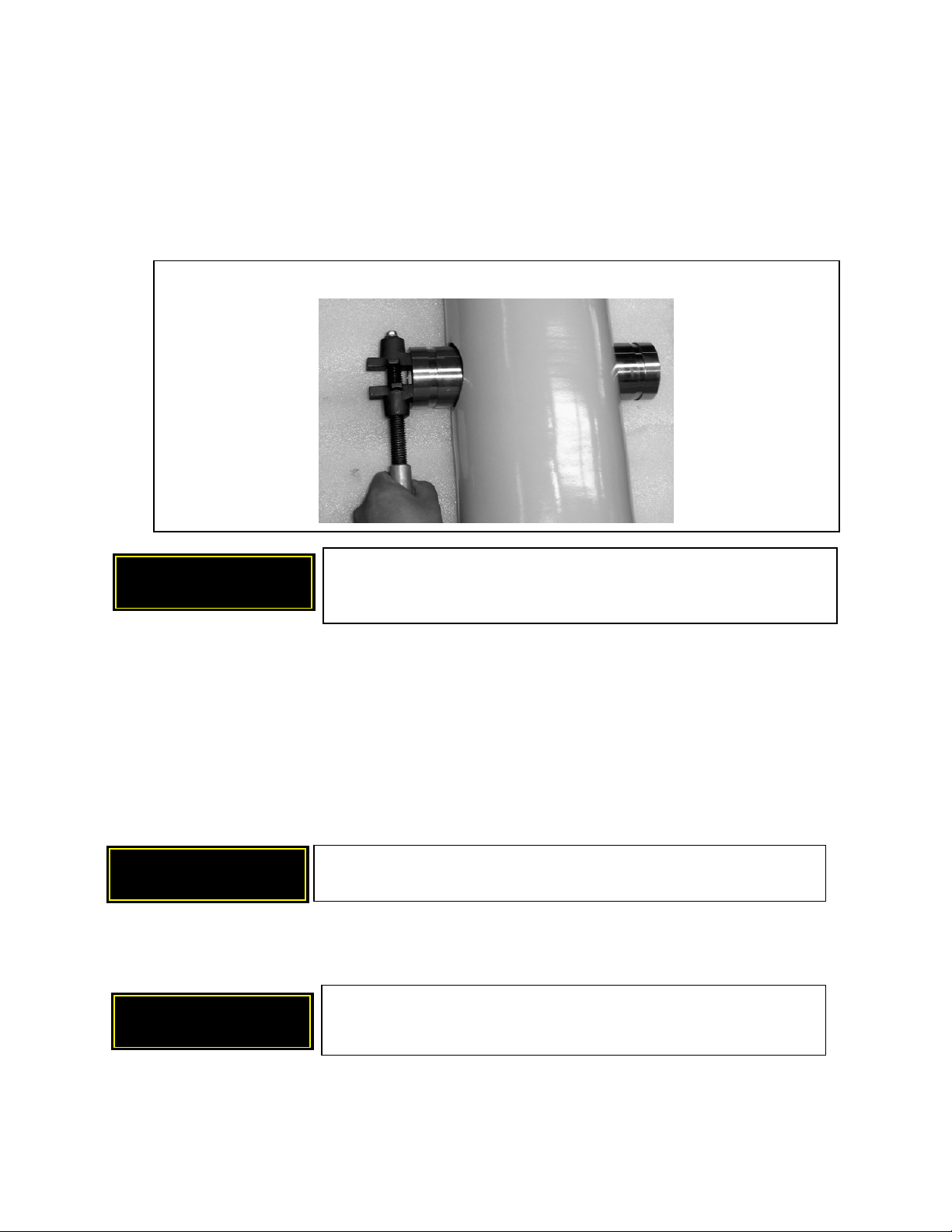
3. Remove low pressure LP inlet port (LP IN) from the end of the PX unit using an inside wrench or a
strap wrench. See Figure 8.1.
When handling and installing a PX unit, do not drop the unit or put
undue strain on the port fittings to avoid internal damage.
Make sure the system is fully depressurized prior to
disconnecting the PX unit.
Figure 8.1 - Remove LP IN port from the end of unit
CAUTION

4S-SERIES PRESSURE EXCHANGER ENERGY RECOVERY DEVICES
Energy Recovery, Inc. 18 ERI Document Number 80022-01-04
4. Remove the six (6) socket head cap screws from the access cover(s).
5. Remove fiberglass locking ring segments. It may be necessary to tap down on the access cover to
relieve compression between the access cover and locking rings. See Figure 8.2 below.
6. Remove access cover by one of the following methods:
a. If using Energy Recovery, Inc. 4S Series Tool Kit, bolt the slide hammer onto the access cover.
Pull access cover.
b. If slide hammer is not available, reinstall LP port into access cover with flexible coupling as
shown in Figure 8.3. Pry off the access covers with a claw hammer or a crow bar. Use a section
of the segmented locking ring to protect the vessel housing from damage while prying.
7. Remove the low-pressure nipple.
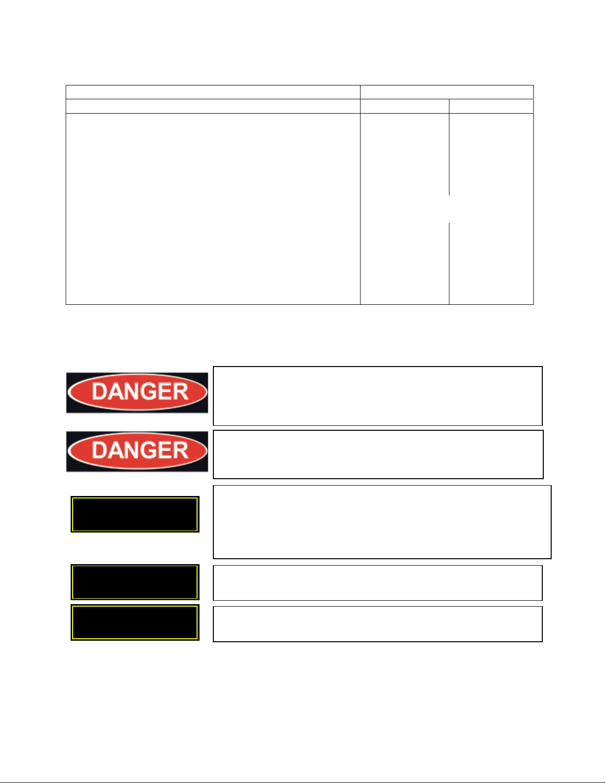
8. Mark the vessel to facilitate correct alignment of the cartridge during reassembly. See Figure 8.4.
9. Thread the lifting eye bolt (5/16”-18) into the standoff on the ceramic cartridge. Extract the ceramic
cartridge. See Figure 8.5. For Single Rotor 4S Series PXs (PX-45S, PX-70S or PX-90S), the ceramic
cartridge must be removed from the seawater (LP IN / HP OUT) end.
10. Stand the ceramic cartridge on blocks allowing clearance for the tension bolt, nuts, and stand-offs on
the bottom of the cartridge. See Figure 8.6 which illustrates the correct orientation of the cartridge.
Figure 8.3 – Pry off access cover using LP port with flexible coupling
Protect edge of
vessel with locking
ring segment LP port
Flexible
coupling
NOTE: Metal objects can chip or crack ceramic. Use caution when
handling ceramic components to avoid damage.
CAUTION
Figure 8.2 – Remove cap screws, locking rings and access cover from
the end of unit. Tap down to loosen access cover if necessary.
4S-SERIES PRESSURE EXCHANGER ENERGY RECOVERY DEVICES
Energy Recovery, Inc. 19 ERI Document Number 80022-01-04
11. Mark the ceramic sleeve with a pencil or marker to assure that correct orientation is retained as shown
in Figure 8.6. The ceramic components must be returned to the vessel in the same orientation they
were removed. Use a pencil or marker to write “SEAWATER” or “BRINE” on the sleeve to assist
with reassembly. The seawater endcover has an O-ring on the outside.
12. Remove the stand-offs from the both ends of the tension rod assembly.
13. Remove the nuts and washers from both ends of the tension rod assembly.
14. Lift the ceramic endcover off the rotor and sleeve. Set the endcover on a clean surface with the
polished side oriented upwards.
15. Lift the rotor and sleeve off the bottom endcover. DO NOT ALLOW THE ROTOR TO COME OUT
OF THE SLEEVE. Place the rotor and sleeve on a clean surface. If the rotor comes out of the sleeve,
the following procedure should be applied:
a. Clean the rotor and sleeve. Rinse liberally.
b. Inspect rotor and sleeve. Remove all debris. Rinse again if necessary.
c. Identify the end of the rotor marked “CHK”. Place the rotor on a flat clean surface with the end
marked “CHK” oriented upward.
d. Identify the end of the sleeve marked “CHK”. If the sleeve is marked “CHK”, orient the end
marked “CHK” upward. If the sleeve is marked “CHK SWP”, orient the end marked “CHK
SWP” downward.
e. Slowly slide the sleeve onto the rotor. This is a very tight fit and requires a gentle touch. Do not
force the sleeve on by pressing or hitting it. The sleeve should slide on easily. If the rotor and
sleeve become bound, use hot water on the sleeve to loosen it from the rotor.
Figure 8.6 – Stand ceramic cartridge on blocks
Mark sleeve with
p
encil to remember
orientation
Seawater end has
O-ring on endcover
Figure 8.5 – Thread lifting eye into standoffFigure 8.4 – Mark vessel to recall alignment
Place a
mark in line
with LP
countersink
Standoff
LP nipple
countersink
4S-SERIES PRESSURE EXCHANGER ENERGY RECOVERY DEVICES
Energy Recovery, Inc. 20 ERI Document Number 80022-01-04
f. Contact Energy Recovery, Inc. immediately if ceramic is damaged or broken or if problems are
encountered. Do not attempt to reassemble a PX unit with damaged or broken parts.
16. Remove the low pressure nipples.
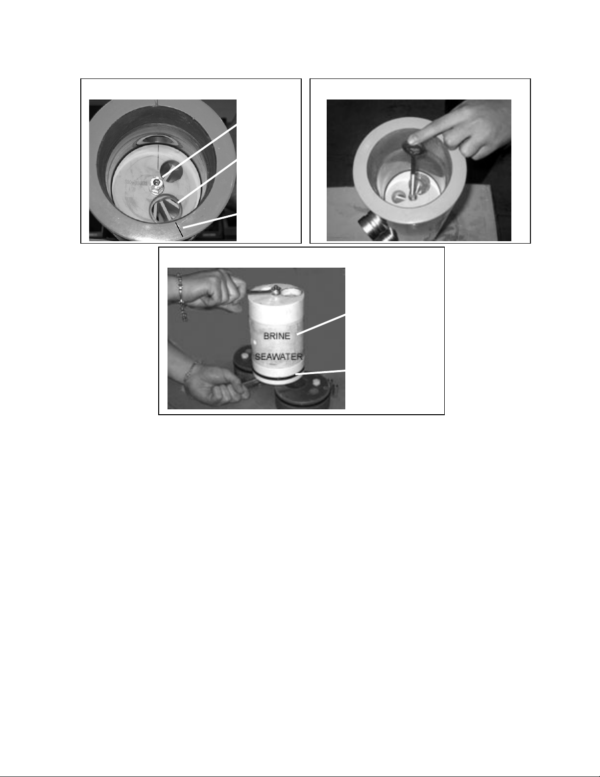
17. The PX-140S contains a center manifold which is not normally removed. However, the center
manifold can be removed by removing both side ports using an inside wrench as shown in Figure 8.7.
After removal of the ports, the center manifold will easily slide out of the vessel.
8.2 Assembly Procedure
This assembly procedure assumes that the PX energy recovery device has been disassembled per the
previous section. All parts should be carefully cleaned with soap and water prior to assembly to assure
that no dirt or debris contaminates the PX unit. All parts should be thoroughly inspected for damage
and/or debris prior to reassembly. O-rings should be carefully inspected for damage and should be
replaced if damage is apparent. Do not attempt to reassemble a PX unit with damaged or broken parts.
Refer to Section 7.0 for a listing of spare parts kits and tool kits useful for disassembly and reassembly of
a PX unit. Refer to Section 13.0 for a complete listing of PX device component names and the bill of
materials for PX unit assembly.
1. Insert dowel pins into the 3 holes in the face of one endcover as shown in Figure 8.8. Make sure the
dowel pins insert fully without binding and without being shaved. If the pins bind, remove and clear
pins and holes of any debris.
2. Place the rotor and sleeve on the endcover. Make sure that the dowel pins in the endcover line up with
the 3 holes in the sleeve as illustrated in Figure 8.9.
Use extreme caution when handling ceramic components. Do not
attempt to reassemble a PX unit with contaminated, damaged or broken
parts. Permanent damage may result.
Figure 8.7 – Remove PX-140S side ports with inside wrench if removing center manifold
CAUTION
Do not attempt to reassemble a PX unit with contaminated, damaged
or broken parts. Permanent damage may result.
CAUTION
Alignment pins must not bind or be shaved during installation.
Carefully inspect ceramic contact lines after installation for any
indication of
p
in dama
g
e or bindin
g
.
CAUTION
Table of contents
Other Energy Recovery Test Equipment manuals


Popular Test Equipment manuals by other brands


Waygate Technologies
Waygate Technologies Krautkramer USM 100 operating manual

Apera
Apera DO8032 installation manual

Masibus
Masibus iCal LC-11 user manual

Min
Min DS203 user manual

National Instruments
National Instruments USB Digitizers NI USB-5132 Getting started guide

Unitest
Unitest TELARIS LOOP instruction manual

Macherey-Nagel
Macherey-Nagel URYXXON 500 user manual

PRESTON PRESSURE
PRESTON PRESSURE PS-625 Operation and maintenance manual

Franklin Fueling Systems
Franklin Fueling Systems HEALY VP1000-220-IC manual

Fluke
Fluke SHAFTALIGN touch Safety and General Information

Hanna Instruments
Hanna Instruments HI 98121 user manual

IDEAL
IDEAL OTDR Quick reference guide