8
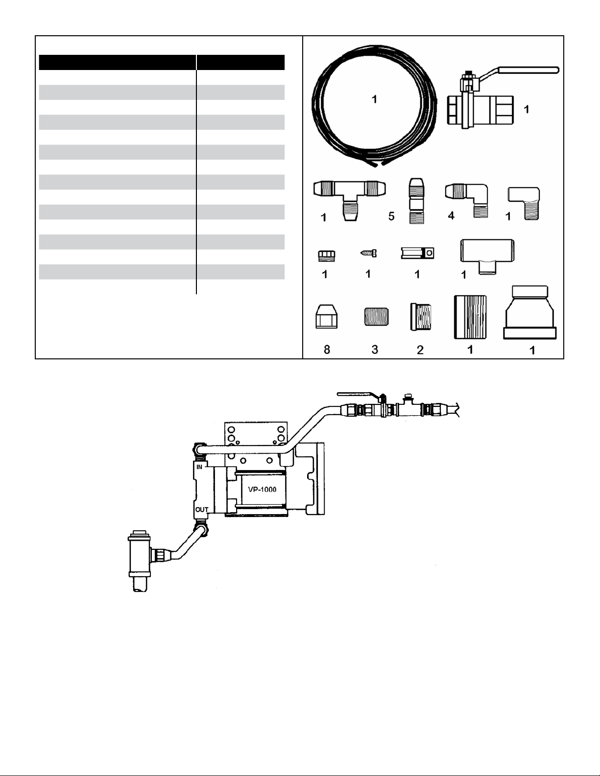
Installing the VP1000-220-IC System
Mounting the Vacuum Pump & Electrical
Conduit Assembly
The VP1000-220-IC System must be installed by a
licensed petroleum technician following all applicable
federal and local codes / regulations.
Warning Disable and tag-out all electrical feeds
into the dispenser. No electrical power
is allowed to the dispenser during the
installation of the vacuum pump and
control module.
The recommended mounting position of the VP1000-
220-IC vacuum pump is with the vacuum inlet and the
electrical connection facing upwards towards the top of the
dispenser.
• The vacuum pump’s performance is not affected by the
mounting location within a dispenser.
• The vacuum pump can be mounted at any location
within the hazardous area of a dispenser if all applicable
NFPA codes are followed.
• The installation must use “UL” approved electrical
conduit, explosion-proof junction box, and electrical
union as required components connecting the VP1000
vacuum pump to the potted conduit.
The vacuum pump can be mounted on any solid surface
or dispenser brace suitable to support the weight of the
pump (32 lbs. / 14.51 Kg). The black steel bracket that is
attached to the VP1000-220-IC Vacuum Pump can be
removed and rotated (3 different mounting positions) so
as to achieve the recommended mounting position of
the pump. If additional support is needed, the use of the
universal steel bracket supplied in the universal hardware
kit is recommended.
1. Begin the installation by mounting the vapor pump
in the hazardous portion of the dispenser. Do not
nal tighten the mounting bolts at this time.
2. Install the Potted Conduit Assembly in an available
barrier knockout (Figure 9). The potted conduit
assembly is used for the electrical conduit
transition from the hazardous area into the
electronic area where the VP1000-220-IC will be
interfaced with existing dispenser electronics.
3. The opening required through the vapor barrier for
the potted assembly must be 1-1/8" in diameter.
Installers can use a sheet metal punch to create
the opening or use an existing knock-out if
available.
4. Remove the top hex nut and washer from the
potted conduit assembly. Guide the assembly
through the knock-out, replace the washer, thread
the hex nut back onto the assembly, and hand-
tighten the assembly into place. If the dispenser
has dual vapor barriers, the rubber washer is
installed on the top side of the lower deck. (See
Figure 9).
Some dispensers have 2 decks.
Dispenser deck(s) between
hydraulics and electronics.
Free space
between decks
List of items included with potted conduit
1. Hex jam nut (2 required)
2. Washer, metal (2 required)
3. Washer, rubber (1 required) if
dispenser has two decks between
hydraulic area and electronics area.
4. ¾" x 6" potted conduit
(36" of wires at module end)
(42" of wires at VP1000-220-IC end)
Wires from
potted conduit
to VP1000-220-IC
Figure 9: List of items Included with Potted Conduit
To power supply
and solenoid signal
To VP1000-220-IC
vacuum pump
Figure 10: Junction Box Wiring
5. After the potted conduit and the VP1000 vacuum
pump are in place (not nal tightened), you can begin
to make up the electrical conduit that will connect the
two components. Keep in mind that an electrical union
and the explosion proof junction box must be installed
between the two points.