Energy Recovery Pressure Exchanger PX Q400 User manual

PX Q400 Energy Recovery Device
Energy Recovery Document Number 80882-01-00
1
TABLE OF CONTENTS
1. INTRODUCTION ................................................................................................................. 3
ABOUT THIS MANUAL ......................................................................................... 3
DEVICE BASICS.................................................................................................... 3
PX DEVICE IN RO SYSTEMS................................................................................... 4
CIRCULATION PUMP WITH PX DEVICES ............................................................... 4
PX OPERATIONAL LIMITS..................................................................................... 4
2. SAFETY............................................................................................................................... 5
HIGH PRESSURE REMAINS AFTER SHUTDOWN .................................................... 6
LOW PRESSURE ISOLATION AND OVER-PRESSURIZATION .................................... 6
HYDROSTATIC TESTING ....................................................................................... 7
3. STORAGE AND HANDLING INFORMATION......................................................................... 7
STORAGE AND HANDLING INFORMATION........................................................... 7
LIFTING............................................................................................................... 7
LIFTING EQUIPMENT ..............................................................................................7
HORIZONTAL LIFTING PROCEDURE ........................................................................8
VERTICAL LIFTING PROCEDURE .............................................................................. 9
INSTALLATION .................................................................................................... 9
4. OPERATION........................................................................................................................ 10
FEEDWATER SUPPLY ........................................................................................... 10
START AND STOP PROCEDURES........................................................................... 10
STARTUP SEQUENCE ..............................................................................................10
SHORT TERM SHUTDOWN SEQUENCE ................................................................... 11
LONG TERM SHUTDOWN SEQUENCE..................................................................... 12
FEEDWATER FILTRATION .................................................................................... 12
FLOW CONTROL.................................................................................................. 12
LUBRICATION FLOW RATE ......................................................................................12
HIGH-AND LOW-PRESSURE FLOW RATES .............................................................. 13
FLOW BALANCE ...................................................................................................... 13
4.5. FLUSHING........................................................................................................... 14
4.6. PURGE AIR .......................................................................................................... 15

PX Q400 Energy Recovery Device
Energy Recovery Document Number 80882-01-00
2
5. SERVICE ............................................................................................................................. 15
SPARE PARTS AND TOOL KITS .............................................................................. 15
DISASSEMBLY PROCEDURE ................................................................................. 16
DISASSEMBLY PROCEDURE FOR THE PX DEVICE ON THE RACK OR PIPING ............. 17
PX DISASSEMBLY.....................................................................................................18
ASSEMBLY PROCEDURE ...................................................................................... 24
CARTRIDGE ASSEMBLY ...........................................................................................24
6. TROUBLESHOOTING .......................................................................................................... 30
PRELIMINARY PROCEDURES................................................................................ 30
INSTRUMENTATION............................................................................................ 30
TROUBLESHOOTING GUIDE ................................................................................ 31
7. LEARNING MORE AND CONTACTING ENERGY RECOVERY.................................................. 33
8. REVISION LOG.................................................................................................................... 33

PX Q400 Energy Recovery Device
Energy Recovery Document Number 80882-01-00
3
1. INTRODUCTION
About This Manual
This manual contains instructions for the installation and operation of Energy Recovery, Inc.
PX Q400 energy recovery devices for Reverse Osmosis (RO) systems. This information is
provided to ensure the long life and safe operation of your PX® Pressure Exchanger® (PX)
energy recovery device. This manual is intended for use by personnel with training and
experience in the installation and operation of fluid handling systems. For additional information
regarding using the PX device in RO systems, refer to Energy Recovery’s website:
www.energyrecovery.com or contact Energy Recovery customer service.
Device Basics
The PX energy recovery device transfers pressure energy from the RO high-pressure concentrate
reject stream to a low-pressure feedwater stream. It does this by putting the streams in direct,
momentary contact in the ducts of a rotor. The rotor is fit into a ceramic sleeve enclosed
between two ceramic end covers with precise clearances that, when filled with high-pressure
water, create an almost frictionless hydrodynamic bearing. The rotor spinning inside the
hydrodynamic bearing is the only moving part within the device.
Figure 1-1: Typical flow path of RO system with PX technology
C
A
B
F
I
G
H
D
E
PX Q400 Energy Recovery Device
Energy Recovery Document Number 80882-01-00
4
PX Device in RO Systems
Figure 1-1 illustrates a typical flow schematic for a RO system equipped with a PX device. There
are two independent flow paths in the PX device, the low-pressure (LP) side [B to H] and the
high-pressure (HP) side [G to D]. The reject concentrate from the RO membranes [G] passes
through the PX device or an array of devices operating in parallel. The pressure of the
concentrate reject is transferred directly to a portion of the incoming feedwater at up to 98%
efficiency. This pressurized feedwater stream [D], which is nearly equal in volume and pressure
to the concentrate reject stream [G], passes through a circulation pump. The circulation pump
propels flow in the high-pressure loop [E-F-G-D] at a rate controlled by either a variable
frequency driver on the motor or a control valve at the discharge of the circulation pump. Fully
pressurized feedwater from the circulation pump merges with flow from the high-pressure
pump discharge [C] to feed the membranes [F].
Circulation Pump with PX Devices
In the typical RO system illustrated in Figure 1-1, a circulation pump is required to move water
through the membranes and PX device or array. The high-pressure flow through the PX unit(s)
is controlled by either a variable frequency drive operating the circulation pump or a flow control
valve at the circulation pump discharge. Recommended practice is to use a slightly oversized
circulation pump to accommodate for the projected range of concentrate flow and head
requirements. The head requirements are a sum of the pressure losses from the membrane,
piping, and PX device differential pressure (head). Seasonal variations, membrane fouling, and
other process variations should also be considered when sizing your circulation pump. Energy
Recovery carries a line of circulation pumps with capacities from 20 gpm (4.5 m3/hr) up to 2,200
gpm (500 m3/hr). Energy Recovery circulation pumps can be installed on the same manifold to
run in parallel to achieve higher capacities.
PX Operational Limits
Successful operation of the PX Q400 energy recovery device requires observation of some basic
operating conditions and precautions. The PX unit must be installed and operated in accordance
with this manual and good industrial practice to ensure safe operation and a long service life.
Failure to observe these conditions and precautions can result in reduced service life, damage

PX Q400 Energy Recovery Device
Energy Recovery Document Number 80882-01-00
5
to the equipment, and/or harm to personnel. For operational conditions, refer to the Technical
Data Sheet of the product. Table 1-1 provides a summary of system performance limits.
Table 1-1: System Performance Limits
Parameter
Operational values limits
English Units
Metric Units
Maximum high pressure (HP IN or HP OUT)
1,200 psig
82.7 bar
Maximum feedwater inlet pressure (LP IN)
145 psig
10 bar
Storage, operating, and feedwater temperature range
33-120 °F
1-49 °C
pH range
1-12 (short term at limits)
Further information about PX or other Energy Recovery products or service can be found by
contacting Energy Recovery at:
Energy Recovery Inc.
1717 Doolittle Drive, San Leandro, CA 94577
Tel: 1 510 483-7370
www.energyrecovery.com
For parts and/or inquiries, please e-mail: [email protected].Be sure to
include model and serial number along with company name and location in the e-mail.
2. SAFETY
The PX device is designed to provide safe and reliable service; however, it is used in a high-
pressure industrial process. Operations and maintenance personnel must follow the basic safety
rules associated with high-pressure equipment and seawater RO processes. Proper installation
and maintenance of shutdown devices and over-pressure and over-flow protection equipment
are an essential part of any RO system. Operation of the PX device outside of the designed
operating range can result in damage and may be unsafe.
PX Q400 Energy Recovery Device
Energy Recovery Document Number 80882-01-00
6
The flags shown and defined below are used throughout this manual. They should be given
special attention when they appear in the manual.
High-Pressure Remains After Shutdown
The high-pressure section of a RO system equipped with a PX energy
recovery device can remain pressurized after shutdown. Pressure
decreases as water slowly flows through the hydrodynamic bearing of the
PX unit. If more rapid system depressurization during shutdowns is required, the system should
be designed with accommodating valves and piping. Always make sure the RO system is fully
depressurized before disconnecting any piping or equipment.
Low-Pressure Isolation and Over-Pressurization
If the low-pressure side of the PX energy recovery device is isolated before
the high-pressure side is depressurized, the PX unit or the low-pressure
piping may be damaged by over-pressurization. High-pressure water will
seep through the PX device’s hydrodynamic bearing to low-pressure regions in the PX unit. To
prevent this over-pressurization scenario, use appropriate pressure relief valves, rupture disc
and/or depressurization procedures.
These flags denote highlighted items.
These flags denote items that, if not strictly observed, can result in
serious injury to personnel.
NOTE
CAUTION
DANGER
These flags denote items that, if not strictly observed, can result in
damage or destruction to equipment.
DANGER
DANGER
PX Q400 Energy Recovery Device
Energy Recovery Document Number 80882-01-00
7
Hydrostatic testing
The PX shall not be subjected to hydrostatic testing outside of ERI’s test
facility. If hydrostatic testing of the plant piping and machinery is needed,
please remove the PX before doing so. Failure to do so may cause damage
to the device and/or injury.
3. STORAGE AND HANDLING INFORMATION
Storage and Handling Information
PX devices are packed with plugs installed on the connection ports. Keep the plugs in place until
the unit is to be fitted to the piping. This will keep the inside of the unit clean.
Follow these guidelines to reduce the potential for damage:
•The PX units must never be exposed to temperatures below 33F (1C) or above 120F (49C)
during storage or operation. If possible, store in a climate-controlled building or
warehouse.
•Avoid direct sunlight, rain or weather.
•Never lift or support the units with the end ports or side ports.
•Use a crane for lifting whenever one is available.
Lifting
Lifting Equipment
•Overhead Lift Machine (fork lift, overhead crane, floor crane)
oMinimum rating of 500 Lbs (227kg)
•Qty two (2) Flat-Eye Web sling
oMinimum rating – 1200 lbs (545kg)
oMinimum length – 9 ft (2.7m)
DANGER
DANGER
Always use caution when working with heavy objects – The ERI PX-Q400
weighs approximately 360 LBS (164 KG) – and can be difficult to move and
manipulate.

PX Q400 Energy Recovery Device
Energy Recovery Document Number 80882-01-00
8
Horizontal Lifting Procedure
1) Space two (2) Flat-Eye Web Sling along the outer diameter of the PX as shown in Figure
3-1. Ensure slings are equally spaced with respect to the center-plane of the PX.
2) One sling can be used if configured as “Double Choker Hitch” shown in Figure 3-2.
3) Once unit is properly strapped it can be lifted and transported, to final destination,
carefully using either of these methods:
a. Overhead lift and/or Jib Crane
b. Fork Lift
c. Floor Crane
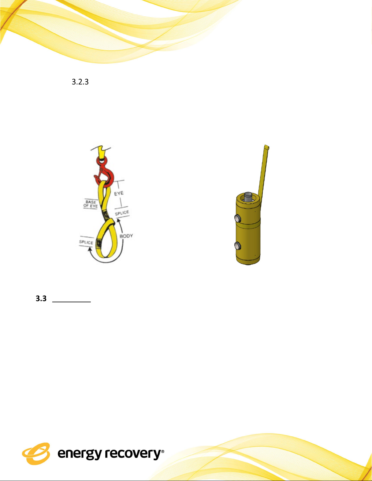
Figure 3-2: Single sling Double Choker Hitch method
Figure 3-1: Space slings evenly along the PX housing.
Center-Plane
PX Q400 Energy Recovery Device
Energy Recovery Document Number 80882-01-00
9
Vertical Lifting Procedure
1) Wrap the PX using the single Sling “Choker” method shown in Figure 3-3.
2) Place Sling below top side-port shown in Figure 3-4. Carefully lift and place unit as
required.
Installation
PX devices can be installed and operated in any orientation. Each unit has four connections
labeled HP IN, HP OUT, LP IN, and LP OUT.
•HP IN is the high-pressure concentrate inlet.
•HP OUT is the high-pressure feedwater outlet to the circulation pump.
•LP IN is the low-pressure feedwater inlet.
•LP OUT is the low-pressure concentrate outlet.
The PX unit must be supported by its housing and not by the pipe fittings. Prevent the PX unit
from supporting piping or manifolds. The PX device should be kept in its original packing until
Figure 3-3: Single Choker method
Figure 3-4: Single sling use on PX

PX Q400 Energy Recovery Device
Energy Recovery Document Number 80882-01-00
10
the initial startup of the RO train. Proper piping, piping support, and housing support must be
employed to minimize external stresses on all pipe fittings. Use shims to support and align the
housing. Suitable flexible couplings should be used for joining fittings and piping. Use only water-
soluble lubricants such as glycerin on coupling gaskets; do not use grease. Please request
dimensional drawings of a PX device and a piping detail for use for piping, manifold, and support
rack design.
Prior to installation of the PX device, all associated piping should be thoroughly flushed to assure
that no debris enters and/or damages the PX unit. Temporary installation of basket strainers at
both inlets to the PX device or PX device array can be used.
4. OPERATION
Feedwater Supply
Standard RO process chemicals are not harmful to the PX.
Start and Stop Procedures
The following procedures are general guidelines for the startup and shutdown of PX unit
systems. Procedure details will vary by plant design. Contact Energy Recovery if your process
design significantly differs from that shown in Figure 1-1. Always ensure that the operating limits
listed in Section 1.5 are followed.
Startup Sequence
1. All valves should be in their normal operating positions.
CAUTION
Thoroughly flush associated piping with clean water before installing the
PX unit. Foreign material entering the unit may cause damage.

PX Q400 Energy Recovery Device
Energy Recovery Document Number 80882-01-00
11
2. Start the feedwater supply pump. The feed flow through the PX unit(s) may or may not
cause the rotor to begin to rotate. Rotation will produce a humming sound that is audible
at close proximity to the PX unit(s).
3. Adjust the feedwater flow to the desired flow rate using the low-pressure outlet flow
control valve (FCV).
4. Open air vent valves to vent the high-pressure piping. This is necessary to allow air to
escape the system and to allow the high-pressure piping to fill with water pushed through
the high-pressure pump by the feedwater supply pump.
5. After the high-pressure piping is full of water, start the circulation pump. Rotor speed will
increase. Bleed any remaining air from the system.
6. Adjust the high and low-pressure flows to the PX unit to make them equal.
7. After the feedwater supply and circulation pump have run for sufficient time to purge all
air from the system, start the high-pressure pump. The RO system pressure will increase
to the point where the permeate flow will approximately equal the flow from the high-
pressure pump. The sound level from the PX unit will increase. Small variations in sound
level and rotor speed are normal.
8. Close the air vent valves.
9. Verify that pressure at the device low-pressure outlet exceeds minimum requirements.
10.Verify the high and low-pressure flow rates. Adjust flows as necessary to achieve balanced
flow to the PX units.
Short Term Shutdown Sequence
1. Throttle the LPOUT FCV to avoid overflow in the LP side of the unit when the high-
pressure pump is turned off.
2. Shut off the main high-pressure pump.
3. Wait until the system pressure drops to the osmotic pressure of the seawater, e.g. 400
psig (28 bar).
4. Shut off the circulation pump.
5. Shut off the feedwater supply pump.
6. If necessary, open a purge valve to expedite depressurization.
PX Q400 Energy Recovery Device
Energy Recovery Document Number 80882-01-00
12
Long Term Shutdown Sequence
If the process is to be shut down for long term (the time frame depends on the characteristics
of the RO system and feedwater), the RO system including the PX units must be thoroughly
flushed with fresh water to remove any salt, and precautions should be taken to inhibit
biological growth. The high-pressure and low-pressure sides of the PX unit must be flushed
separately. The low-pressure side should be flushed with fresh water through the feedwater
feed line to the PX unit and to the concentrate drain. The high-pressure flush is typically
performed by circulating water through the PX unit and the membranes using the circulation
pump. Lubrication flow for the PX device rotors must be provided through the high-pressure
pump or some other injection point in the high-pressure loop during fresh water flushing. The
PX units should receive a final flush with the same solution used to preserve the RO membranes.
Feedwater Filtration
Like the RO membranes, the PX device requires filtered water. Particulates entering the PX
device are passed through to the membranes. Particles entering the PX device may also prevent
the rotor from spinning and can effect performance, resulting in the need to service the device.
The PX device filtration requirement applies during commissioning, normal operation, as well as
the membrane Clean in Place (CIP) process; refer to the technical data sheet for filtration
requirements.
Flow Control
Flow rates and pressures in a typical RO plant will vary slightly over the life of a plant due to
temperature variations, membrane fouling, and feed salinity variations. The PX unit’s rotor is
turned by the flow of fluid through the device. The speed of the rotor is self-adjusting over the
PX unit’s operating range. The ratio of the high and low-pressure flow rates affects the degree
of mixing between the feedwater and concentrate streams that occurs within the unit.
Lubrication Flow Rate
In a PX device, some of the high-pressure water flows through the hydrodynamic bearing to low-
pressure regions in the assembly. The lubrication flow rate varies with system pressure
according to the PX’s performance curves. If the PX device has a damaged o-ring or is damaged

PX Q400 Energy Recovery Device
Energy Recovery Document Number 80882-01-00
13
by debris, overflow, or insufficient discharge pressure, excess lubrication flow may occur.
Monitoring lubrication flow is a good way to check the integrity of an operating PX unit.
Lubrication flow can be monitored using any of the following three methods:
•Measure the flow rate of the low-pressure feedwater to the high-pressure pump and the
flow rate of the permeate. The difference is approximately the lubrication flow rate.
•Measure the flow rate of the high-pressure concentrate to the PX unit and the high-
pressure feedwater from the PX unit. The difference is approximately the lubrication flow
rate.
•Measure the flow rate of the low-pressure concentrate from the PX unit and the low-
pressure feedwater to the PX unit. The difference is approximately the lubrication flow
rate.
Please note that this method of monitoring is to help establish trends. The value obtain may not
be exact.
High- and Low-Pressure Flow Rates
The high-pressure flow through the PX unit is set by adjusting the circulation pump with a
variable frequency drive or with a flow control valve and verified with a high-pressure flow
meter. The flow rate of the high-pressure feedwater out of the PX unit equals the flow rate of
the high-pressure concentrate to the PX unit minus the bearing lubrication flow.
The low-pressure flow through the PX unit is controlled by the feedwater supply pump and a
control valve in the concentrate discharge from the PX unit(s). This valve also adds backpressure
on the PX device required to prevent cavitation. The low-pressure flow rate must be verified
with a flow meter. The flow rate of the low-pressure concentrate from the PX unit equals the
flow rate of the low-pressure feedwater to the PX unit plus the bearing lubrication flow rate.
Flow Balance
The high and low-pressure flows to and from the PX device should be equal or “balanced” for
optimum RO operation. Operating the PX unit with unbalanced flows can result in higher
contamination of the feedwater feed by the concentrate reject. Balanced flows help limit the
mixing of concentrate with the feed. A feedwater inlet flow that is much less than the feedwater

PX Q400 Energy Recovery Device
Energy Recovery Document Number 80882-01-00
14
outlet flow will result in lower quality permeate, increased feed pressure, and higher energy
consumption. For more information refer to Energy Recovery document 80088-01 Mixing
Technical Bulletin or contact Energy Recovery customer service.
4.5. Flushing
There are two types of flush: Feedwater Flush and Fresh Water or Permeate Flush. Regardless
of the flush water used, all parts of the PX device must be flushed, i.e. low-pressure flow
channels, high-pressure flow channels, and lubrication channels.
Feedwater Flushing is part of a normal shutdown sequence as described in Section 4. After both
permeate and concentrate production have ceased, flow on both the high-pressure and low-
pressure sides of the PX devices continues. The flow path of the Feedwater Flush, with reference
to Figure 1-1, is B-C-D-E-F-G-H driven by the feedwater pump and the circulation pump. A
Feedwater Flush is typically continued until conductivity measurements at process locations G
and H are satisfactory (TDS close to feedwater TDS).
A Permeate Flush or Fresh Water Flush is performed on a partially or fully depressurized system.
This is accomplished by introducing permeate simultaneously to the PX device low-pressure
inlet [B] and either to the high-pressure pump inlet [A] or through some other injection point
such as a CIP connection. Permeate may be produced during this flushing process. If so, it may
be necessary to block permeate flow to divert lubrication flow through the PX devices. The
circulation pump must be run to flush HP side of the PX device (s).
For more detail information refer to relevent Energy Recovery technical bulletins.

PX Q400 Energy Recovery Device
Energy Recovery Document Number 80882-01-00
15
4.6. Purge Air
Entrained or trapped air or other gases must always be purged from the RO system before
pressurizing the system. Entrained air in a pressurized system can result in damage to the PX
unit. Prior to pressurizing the RO system, vent or flush for sufficient time to allow for the removal
of all air from the RO system.
5. SERVICE
Spare Parts and Tool Kits
The PX Q400 energy recovery device needs no scheduled periodic maintenance. However, in the
event that disassembly is desired or required, the PX Q400 unit is designed so that it can be
assembled and disassembled in the field with only basic tools and equipment. These tools are
listed in Table 5-1. These tools, with the exception of the hoist and torque wrench, are included
in the PX Q400 tool kit (Energy Recovery Part Number 20469-01). In addition, the PX Q400 unit
can be mounted on a stand or on blocks to facilitate service, or the LP connection port can be
unthreaded in order to support the unit on the housing.
Entrained or trapped air must be purged from the RO system before every
pressurization.
CAUTION
PX Q400 Energy Recovery Device
Energy Recovery Document Number 80882-01-00
16
Table 5-1: Tool Kit 20469-01 bill of materials
Part Number
Description
Purpose
20471-01 KIT, TOOL, HEAD PULLER, 9"
Tool designed to facilitate removal of Head Assembly.
Glycerin included to lubricate O-rings.
10608-01 TOOL, REMOVAL, INTERCONNECT, 3"
Tool to remove Interconnects.
43684-01 TOOL, INSTALLATION, O-RING, 9" SIDE PORT
Tool to reduce O-ring damage during install or removal
of Cartridge.
30207-01
TOOL, LIFTING STRAP, FABRIC
Attached to the housing to support lifting purposes.
10506-01 NUT, LIFTING EYE, 5/8"-11, 316
Lifting Eye for cartridge. To be used in conjunction with
All Thread found in 20471-01 and Coupling Nut 30092-
01.
30092-01 NUT, COUPLING, 1/2"-13, TO, 5/8"-11, RED
Couples All Thread found in 20471-01 with Cartridge.
30100-01
ROD, SPINNING, ROTOR
Rod to help spin the rotor during assembly.
10130-01 WRENCH, ALLEN, TEE, 1/4"
Tool to remove socket head cap screws from head
assembly.
10137-01
WRENCH, COMBO, 3/4", CARBON STEEL
Tool for Hex Bolts.
10225-01
ANTI-SEIZE, .25 OZ, TUBE, NICKEL, MSDS
REQUIRED
Anti-Seize for threaded connections.
10327-01
WRENCH, STRAP, 3/4" MIN, 6-5/16" MAX
Tool designed to install and remove LP connection ports.
10329-01
WRENCH, CRESCENT, 6"
Tool for Hex bolts.
10085-01
NUT, LIFTING EYE, 1/2"-13, 316
Lifting Eye for cartridge
Replacement seals and alignment pins are included in Energy Recovery’s standard spare parts
kits (Energy Recovery Part Number 20467-01). One spare parts kit should be used each time a
PX unit is opened for service.
Replacements for other components in the PX assembly are available. Refer to assembly
drawing for PX component descriptions, part numbers, and the bill of materials.
Disassembly Procedure
CAUTION
Metal objects can chip or crack ceramic. Use caution when handling ceramic
components to avoid damage.
PX Q400 Energy Recovery Device
Energy Recovery Document Number 80882-01-00
17
Disassembly Procedure for the PX Device on the Rack or Piping
1. Depressurize all high-pressure and low-pressure piping to and from the PX unit.
2. Close all valves to and from the PX unit/rack or drain system.
3. Disconnect and remove the low-pressure piping from the upward facing end of the unit.
See Figure 5-2 as reference.
4. If more access is required, the PX can be removed from the rack.
a. Remove the all HP and LP couplings from the PX.
b. Remove the all HP and LP pipes connected to the PX.
c. Install sling around the PX as described in Section 3.2.
d. Remove the Saddle and Strap from the PX.
e. Remove the PX from the rack following the procedure listed in Section 3.2.
i. Bottom LP port may need to be removed if access is needed. Refer to
Section 5.2.2 Step 1.
5. Proceed with disassembly as directed in Section 5.2.2.
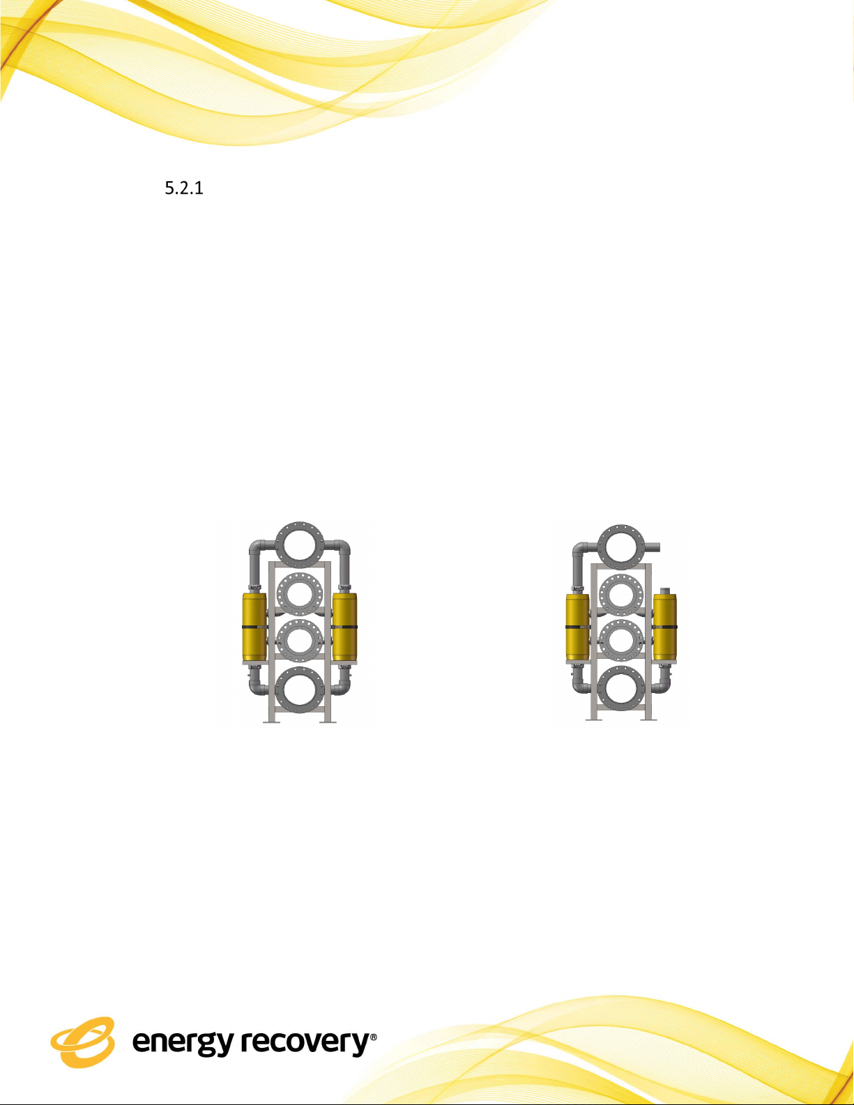
Figure 5-1: PX device on array rack
Figure 5-2: LP port removed on array rack
PX Q400 Energy Recovery Device
Energy Recovery Document Number 80882-01-00
18
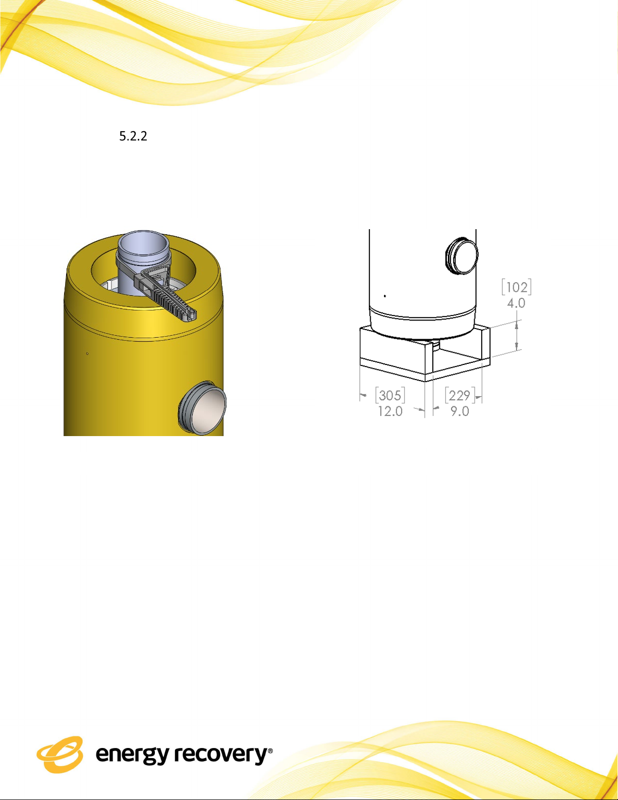
PX Disassembly
1. Unscrew and remove the bottom LP port Figure 5-3. Otherwise, use blocks or a stand to
support the unit by the bottom end of the fiberglass housing shown in Figure 5-4. Do not
support the unit or apply stress to the low-pressure port.
2. Remove four (4) 5/16-inch socket-head cap screws, two (2) Securing Ring, and three (3)
Segmented Lock Ring from the top of the PX unit using a 1/4-inch Allen wrench as shown
in Figure 5-5.
a. Tip: Segmented Lock Ring maybe compressed due to pressurization of the PX. In
this instance, gently tap on the Bearing Plate with a plastic or wooden rod to loosen
the Head Assembly.
Figure 5-3: PX Q400 with Pipe Strap tool Figure 5-4: PX Support block shown as reference
Typical Dimensions shown in Inches [mm]

PX Q400 Energy Recovery Device
Energy Recovery Document Number 80882-01-00
19
3. Extract Head Assembly from the housing using an Energy Recovery Head Puller tool
20471-01 shown in Figure 5-6. Assisted lifting can be achieved using the All-thread and
Lifting Eye 5/8-11” as shown in Figure 5-7. Take care not to apply stress to the LP port if
it is still in place. Always use a wood block to protect the edge of the housing if force is
necessary to remove the head assembly.
a. Estimated weight of the Head Assembly is 25 lbs (11.3 kgs).
(2) Securing Ring
(4) 5/16-inch socket-head screw
Figure 5-5: Disassembly of PX Segmented and Securing Rings
(3) Segmented Lock Ring
Bearing Plate
Figure 5-6: Head puller tool, PN 20471-01
Figure 5-7: Assisted lifting of the Head Assembly
Head Assembly - 25lbs
(11.3kg)
•LP Port
•Bearing Plate
•Seal Plate
All-thread located in Head
Puller Tool 20471-01.
Table of contents
Other Energy Recovery Test Equipment manuals


