Energy GOLDEN SIGMA SU340U170KC User manual

SYL (Ningbo) Battery Co., Ltd. UM-SU340U170KC-V02-22-EN
INSTALLATION MANUAL
MANUEL DE L'UTILISATEUR
GOLDEN SIGMA
SU340U170KC

2
REVISION HISTORY
REV.
DESCRIPTION
DATE
BY
REVIEW
V01
[DRAFT] Issued for review.
12/15/2021
Hangjian
Zhang, Liangke
Wu, Yating You
Lei Zhang,
Jackie
Jing
V02
[DRAFT] Optimizing some content.
01/27/2022
Lebo Wei, Xin
Gao,
Zhengtong
Zhou
Lei Zhang
Contributors of this manual also include Hangjian Zhang, Weining Chu, Zhian Ju, Pinhao
Bao, etc.

3
IMPORTANT NOTICE
CAUTION
READ THIS MANUAL BEFORE PERFORMING ANY INSTALLATION ACTION!
IF YOU HAVE ANY UNCERTAINTY REGARDING THE CONTENT OF THIS
MANUAL, PLEASE CONTACT SYL FOR ADVICE OR CLARIFICATION.
IMPORTANT
KEEP THIS MANUAL IN A SECURE PLACE FOR FUTURE REFERENCES!
CAUTION
THIS DOCUMENTATION ALONG WITH INFORMATION INSIDE IS THE
PROPERTY OF SYL (NINGBO) BATTERY CO., LTD.
COPYRIGHT © 2021 SYL (NINGBO) BATTERY CO., LTD. ALL RIGHT
RESERVED.
THIS DOCUMENTATION IS FOR THE SOLE PURPOSE OF THE INSTALLATION
OF SYL BESS PRODUCTS. ANY PART OF THIS PUBLICATION SHALL NOT BE
USED FOR ANY OTHER PURPOSE, AND SHALL NOT BE COPIED,
REPRODUCED, DISCLOSED, TRANSMITTED, STORED IN A RETRIEVAL
SYSTEM, OR TRANSLATED INTO ANY HUMAN OR DIGITAL LANGUAGE, IN
ANY FORM, BY ANY MEANS, IN WHOLE OR IN PART WITHOUT PRIOR
WRITTEN CONSENT FROM SYL (NINGBO) BATTERY CO., LTD.
IMPORTANT
ALTHOUGH SYL HAS MADE ITS BEST EFFORT TO ENSURE THE ACCURACY
OF THIS DOCUMENTATION, SYL (NINGBO) BATTERY CO., LTD., TAKES NO
RESPONSIBILITY FOR THE ERRORS/TYPOS THAT MAY APPEAR HEREIN.
THIS DOCUMENTATION IS SUBJECT TO CHANGES WITHOUT PRIOR
NOTICE.

4
TABLE OF CONTENTS
REVISION HISTORY .................................................................................................... 2
IMPORTANT NOTICE ................................................................................................. 3
TABLE OF CONTENTS ................................................................................................ 4
LIST OF FIGURES......................................................................................................... 6
LIST OF TABLES........................................................................................................... 7
ACRONYMS AND DEFINITIONS.......................................................................... 8
ABOUT THIS MANUAL ....................................................................................... 10
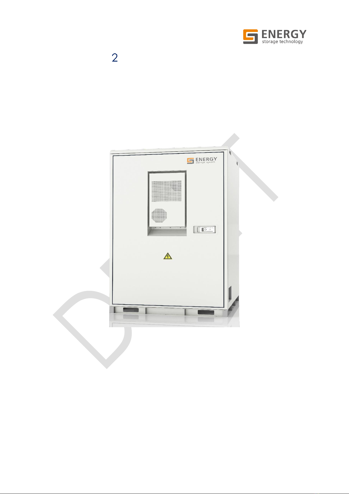
2.1 APPLICABLE PRODUCT........................................................................................ 10
2.2 TARGET GROUP................................................................................................... 10
2.3 MAIN FEATURE ..................................................................................................... 11
2.4 LEVELS OF SAFETY INSTRUCTIONS ....................................................................... 11
2.5 SYMBOLS ON THE PRODUCT............................................................................... 12
SAFETY GUIDELINES .......................................................................................... 15
3.1 LOCK OUT TAG OUT............................................................................................ 15
3.1.1 OPERATION OF BCP DOOR BUTTON ................................................................... 15
3.1.2 CABINET LOCK OUT TAG OUT PROCEDURE ....................................................... 16
3.2 GENERAL PRECAUTIONS..................................................................................... 16
3.3 FIRST-AID MEASURES............................................................................................ 18
3.4 HANDLING GUIDELINES....................................................................................... 19
3.5 PERSONAL PROTECTIVE EQUIPMENT.................................................................. 20
INSTALLATION ................................................................................................... 21
4.1 MAIN TOOLS AND COMPONENTS FOR INSTALLATION...................................... 21
4.2 PREPARATION FOR INSTALLATION...................................................................... 23
4.2.1 INSTALLATION REQUIREMENTS.............................................................................. 23
4.2.2 INSTALLATION ENVIRONMENT DESIGN................................................................ 26
4.2.3 UNPACKING........................................................................................................... 26
4.2.4 DESCRIPTION OF THE INSTALLATION PROCESS................................................... 27
4.3 INSTALLATION OF BCP......................................................................................... 28
4.4 INSTALLATION OF THE GOLDEN SIGMA ............................................................. 30
4.4.1 INSTALLATION PRECAUTIONS ............................................................................... 30
4.4.2 SITE AND ENVIRONMENTAL REQUIREMENTS ....................................................... 32
4.4.3 INSTALLATION STEPS FOR GOLDEN SIGMA COMBINATION.............................. 33

5
4.4.4 INSTALLATION STEPS .............................................................................................. 37
4.4.5 THE INSTALLATION FOR RUBBER SLEEVE............................................................... 40
ELECTRICAL CONNECTION ............................................................................. 43
5.1 PREPARATION FOR INSTALLATION...................................................................... 43
5.2 BCP ELECTRICAL CONNECTION......................................................................... 44
5.2.1 CONNECT THE COPPER BUSBAR.......................................................................... 46
5.2.2 CONNECT THE INVERTER....................................................................................... 47
5.2.3 GROUND CONNECTION....................................................................................... 49
5.2.4 INCOMING POWER LINE....................................................................................... 49
5.2.5 GOLDEN SIGMA CONNECTION........................................................................... 50
5.2.6 TERMINALS FOR COMBINING CABINETS ............................................................. 50
5.2.7 STATION POWER AND NETWORK CABLE CONNECTION................................... 51
5.3 BATTERY ELECTRICAL CONNECTION.................................................................. 52
5.3.1 GROUNDING.......................................................................................................... 52
5.3.2 COPPER BAR CONNECTION ................................................................................ 52
5.3.3 INSTALLATION OF THE AUXILIARY AND COMM CABLE...................................... 53
5.3.4 BATTERY MODULE JUMPER CONNECTION.......................................................... 60
CONTACT ......................................................................................................... 63

6
LIST OF FIGURES
Figure 2-1: Rendering of SU340U170KC ........................................................................... 10
Figure 3-1: Operation of BCP door button...................................................................... 16
Figure 4-1: Anchoring location and clearance ............................................................. 25
Figure 4-2: Use ropes or straps to fasten the four lifting holes........................................ 27
Figure 4-3: Remove the packing forms ........................................................................... 27
Figure 4-4: System installation and anchoring................................................................ 29
Figure 4-5: the front view and the side view of the cabinet ......................................... 34
Figure 4-6: Cabinet base cover....................................................................................... 34
Figure 4-7: Remove the base cover................................................................................ 35
Figure 4-8: Install rubber sleeve........................................................................................ 35
Figure 4-9: Precaution measure when putting cabinets against each other.............. 36
Figure 4-10:The gap between the two cabinets combination..................................... 36
Figure 4-11: Lifting lug on the Golden Sigma.................................................................. 37
Figure 4-12: Bottom view .................................................................................................. 38
Figure 4-13: Single row installation................................................................................... 38
Figure 4-14: Chemical anchor detail .............................................................................. 39
Figure 4-15: Rubber sleeve............................................................................................... 40
Figure 4-16: The bracket of rubber sleeve ...................................................................... 40
Figure 4-17: The installation port of rubber sleeve.......................................................... 40
Figure 4-18: The structure of the rubber sleeve .............................................................. 41
Figure 4-19: Golden Sigma combination........................................................................ 41
Figure 4-20: Fasten the other end of the rubber sleeve ................................................ 42
Figure 5-1: The internal layout of BCP.............................................................................. 46
Figure 5-2: The cross-sectional view and top view......................................................... 47
Figure 5-3: the fixed BCP of the adapter copper bar.................................................... 47
Figure 5-4: The connection sequence ............................................................................ 48
Figure 5-5: Grounding connection .................................................................................. 49
Figure 5-6: Incoming power line ...................................................................................... 49
Figure 5-7: UPS power terminal ........................................................................................ 50
Figure 5-8: Golden Sigma connection............................................................................ 50
Figure 5-9: terminals for combining cabinets ................................................................. 50

7
LIST OF TABLES
Table 4-1: Tools for system installation ............................................................................. 21
Table 4-2: Main components for installation .................................................................. 22
Table 4-3: The main content and steps........................................................................... 28
Table 4-4: Specific design values .................................................................................... 39
Table 5-1: Tools for electrical connection....................................................................... 43
Table 5-2: The Introduction of BCP .................................................................................. 46
Table 5-3: terminals for combining cabinets list ............................................................. 51
Table 5-4: RS485 repeater connection............................................................................ 55
Table 5-5: Golden Sigma to BCP connection list ........................................................... 56
Table 5-6: Golden Sigma connection list........................................................................ 58

8
ACRONYMS AND DEFINITIONS
1
AC
Alternating Current
2
Ah
Amp-hour
3
BCP
Battery Connection Panel
4
BESS
Battery Energy Storage System
5
BMS
Battery Management System
6
BOL
Beginning of Life
7
BOP
Balance of Plant
8
BOS
Balance of System
9
BSPU
Battery Safety and Protection Unit
10
EMS
Energy Management System
11
EOL
End of Life
12
ESS
Energy Storage System
13
DC
Direct Current
14
FSS
Fire Suppression System
15
HMI
Human Machine Interface
16
HV
High Voltage
17
HVAC
Heating & Ventilation and HVAC
18
IP
Ingress Protection
19
kV
Kilovolt
20
kW
Kilowatt
21
MV
Medium Voltage
22
MW
Megawatt
23
MWh
Megawatt-hour
24
MVA
Mega Volt-Amps
25
MVAr
Mega Volt Amps (reactive)
26
NMC
NiMnCo
27
OSD
Overcharge Safety Device
28
O&M
Operation and Maintenance
29
PCS
Power Conversion System
30
PPA
Power Purchase Agreement

9
31
PPE
Personal Protective Equipment
32
RMU
Ring Main Unit
33
RTU
Remote Terminal Unit
34
SCADA
Supervisory Control and Data Acquisition
35
SOC
State of Charge
36
SOH
State of Health
37
SPDs
Surge Protection Devices
38
SYL
SYL (Ningbo) Battery Co., Ltd
39
TCP
Transmission Control Protocol
40
UPS
Uninterruptable Power Supply

10
ABOUT THIS MANUAL
2.1 APPLICABLE PRODUCT
This installation manual applies to the SYL Golden Sigma energy storage system under
the model number SU340U170KC.
All references to “Golden Sigma”in this manual, unless specifically indicated herein, refer
to the product series mentioned above.
Figure 2-1: Rendering of SU340U170KC
2.2 TARGET GROUP
The tasks described in this document must only be performed by qualified personnel.
Qualified personnel must have the following skills:
➢Training in how to deal with the dangers and risks associated with the installation
of the product.
➢Training in the installation of electrical devices.
➢Knowledge of all applicable laws, regulations, standards, and directives.

11
➢Knowledge of and compliance with this document and all safety information.
CAUTION
SYL’S BATTERIES AND BESS ARE INTENDED AND WARRANTED FOR
INSTALLATION AS DETAILED IN THIS DOCUMENT. VIOLATION OF THE
INSTALLATION PROCEDURES FOR PURPOSES OTHER THAN THOSE
APPROVED BY SYL MIGHT CAUSE DAMAGE TO THE PRODUCTS AND
WILL VOID THE EQUIPMENT WARRANTIES.
2.3 MAIN FEATURE
➢The battery system can detect the battery operating status(Voltage, current,
temperature, SOC/SOH/SOP estimation, etc.). According to the current state of the
battery and the actual performance of the electrical components to adjust the
battery charge and discharge and energy storage.
➢The battery system has functions such as insulation detection, high-voltage sampling,
and status check of safety devices such as fuses. When the battery fails, the system
will report and limit the charge or discharge current or power, delay the opening of
the contactor, and protect the safety of the power system.
➢The battery system can control the refrigeration, heating, and temperature setting of
the HVAC unit.
➢The cabinet body of the Golden Sigma meets the IP54 protection grade and
supports use under outdoor conditions.
➢Golden Sigma is equipped with an aerosol fire extinguishing system, It can detect
the temperature and smoke status in the Golden Sigma in real-time to prevent fire
safety accidents such as accidental battery fire.
2.4 LEVELS OF SAFETY INSTRUCTIONS
To ensure personal and property safety in using the device or to use the device
efficiently, this manual provides relevant instructions that are highlighted by
corresponding symbols. Read the following symbols carefully for better using this manual.
To ensure the safety of personnel and property, please carefully read all safety
instructions in this document before the installation.

12
DANGER
FAIL TO FOLLOW THE INSTRUCTION WITH THIS SYMBOL MAY RESULT IN A
FATAL ACCIDENT, SEVERE INJURY, EVEN DEATH!
WARNING
INDICATES A HAZARDOUS SITUATION THAT, IF NOT AVOIDED, COULD
RESULT IN INJURY OR DEATH.
CAUTION
INDICATES A HAZARDOUS SITUATION THAT, IF NOT AVOIDED, COULD
RESULT IN MINOR INJURY OR DAMAGE TO THE EQUIPMENT.
IMPORTANT
INFORMATION WHICH CONSIDERED IMPORTANT BUT NOT HAZARD-
RELATED. FAIL TO FOLLOW THE INSTRUCTION WITH THIS SYMBOL MAY
RESULT IN EQUIPMENT DAMAGE!
IMPORTANT
INDICATES AN IMPORTANT STEP OR TIP THAT LEADS TO BEST RESULTS, BUT IS
NOT SAFETY OR DAMAGE RELATED.
2.5 SYMBOLS ON THE PRODUCT
HAZARDOUS VOLTAGE, RISK OF ELECTRIC SHOCK OR BURN.
AUTHORIZED PERSONNEL ONLY.

13
DANGER, BE CAREFUL WHEN HANDLING THE BATTERIES.
RECHARGEABLE BATTERIES, CANNOT DISPOSE OF IN THE
HOUSEHOLD WASTE.
DO NOT DAMAGE THE BATTERIES IN SUCH A WAY AS DROP,
DEFORM, IMPACT, CUT, OR SPEARING OBJECT.
NO SMOKING, NO OPEN FLAME, EMBERS, OR SPARKS NEARBY THE
BATTERY, TO AVOID RISK OF FIRE OR EXPLOSION.
KEEP OUT OF REACH OF YOUNG CHILDREN PETS, OR ANIMALS.
HEAVYWEIGHT, SINGLE-PERSON LIFT COULD CAUSE INJURY. USE
ASSISTANCE WHEN MOVING OR LIFTING.
ELECTROLYTE IS HIGHLY CORROSIVE.

14
METAL PARTS OF THE BATTERY CELL ARE ALWAYS LIVE. NEVER
PLACE FOREIGN OBJECTS OR TOOLS ON THE BATTERY.
OBSERVE INSTALLATION AND OPERATION INSTRUCTIONS IN THE
MANUALS BEFORE WORKING ON THE BATTERIES.
WEAR EYE PROTECTION AND PROTECTIVE CLOTHING WHEN
WORKING WITH BATTERIES. OBSERVER ACCIDENT-PREVENTION
REGULATIONS.
WEAR PROTECTIVE GLOVES AND CLOTHING WHEN WORKING
WITH BATTERIES.
PREPARE FIRST-AID BEFORE WORKING WITH BATTERIES.
WHEN ELECTROLYTES LEAK OUT, AVOID CONTACTING WITH EYES,
SKIN, OR CLOTHES. IN EVENTS OF ACCIDENTS, FLUSH WITH WATER
AND GET MEDICAL HELP IMMEDIATELY.
RECYCLABLE.

15
SAFETY GUIDELINES
WARNING
SAFETY FIRST! ALWAYS OBSERVE AND FOLLOW SAFETY INSTRUCTIONS!
3.1 LOCK OUT TAG OUT
DANGER
FOLLOW ALL THE APPLICABLE LOCK-OUT TAG-OUT (LOTO) PROCEDURES
AT ALL TIMES. IF PROPER LOTO PROCEDURES ARE NOT FOLLOWED, IT MAY
RESULT IN SERIOUS INJURY OR DEATH.
WITH POWER APPLIED TO THE BATTERIES, HAZARDOUS VOLTAGES ARE
PRESENT ON SOME COMPONENTS.
TO PREVENT ACCIDENTAL DEATH OR INJURY, DO NOT TOUCH ANY
COMPONENTS WITHIN THE ENCLOSURE UNLESS YOU ARE SPECIFICALLY
DIRECTED TO DO SO. TO REDUCE THE RISK OF ELECTRICAL SHOCK, MAKE
SURE THAT ALL EQUIPMENT IS PROPERLY GROUNDED.
WARNING
ENCLOSURES/CASES SHALL REMAIN CLOSED EXCEPT WHEN ACCESS TO
THE INTERIOR IS REQUIRED. IF POSSIBLE, PERSONNEL SHOULD KEEP A SAFE
DISTANCE FROM ENCLOSURES/ CASES WHENEVER THE EQUIPMENT IS
ENERGIZED. ALWAYS COMPLY WITH LOCAL, STATE, AND NATIONAL LOCK
OUT/TAG OUT (LOTO) GUIDELINES WHEN WORKING WITH OR NEAR THE
BATTERIES. THE LOTO PROCEDURES SHOULD MEET OR EXCEED THE
REQUIREMENTS OF ALL GUIDELINES PRESENTED IN SYL SAFETY
DOCUMENTATION.
COMPLETE THE SITE/LOCAL SAFETY TRAINING BEFORE ENTERING
POTENTIALLY HAZARDOUS AREAS OR BEGINNING WORK ON THE
BATTERIES.
3.1.1 OPERATION OF BCP DOOR BUTTON
STEP1: Please press the e-stop button in case of an emergency.
STEP2: "Local&Remote" button can switch between remote and local.
STEP3: The button on and off can control the opening and closing of the DC circuit
breaker.

16
Figure 3-1: Operation of BCP door button
3.1.2 CABINET LOCK OUT TAG OUT PROCEDURE
DANGER
IT IS HIGHLY RECOMMENDED TO SHUT DOWN THE WHOLE BATTERY BLOCK
UNDER THE SAME BCP TO PERFORM ANY MAINTAINANCE WORK INSTEAD
OF SHUTTING DOWN ONE OR SEVERAL CABINETS IN THE BLOCK. AS THERE
ARE CERTAIN PARTS OF THE CABINET STILL LIVE WITH FATAL VOLTAGE
PRESENTS EVEN THE DISCONNECTING SWITCH ON THE BATTERY
SWITCHGEAR IS OPEN.
DO NOT KEEP THE BATTERY BLOCK IN OPERATION WHILE SERVICING ONE
OF THE CABINETS IN THE BLOCK.
3.2 GENERAL PRECAUTIONS
Follow all safety precautions during the installation of the batteries and the BESS.
DANGER
PLEASE BE AWARE THAT THE BATTERIES PRESENT A RISK OF ELECTRICAL
SHOCK INCLUDING A HUGE SHORT-CIRCUIT CURRENT.

17
DANGER
ARC FLASH HAZARD IS ASSOCIATED WITH BATTERIES. THERE IS A
SERIOUS RISK OF ARC FLASH RELATING TO ANY EQUIPMENT
MODIFICATION. SERIOUS INJURIES CAN OCCUR IN ARC FLASH
INCIDENTS.
WARNING
FIRE MAY OCCUR UNDER CERTAIN FAULT CONDITIONS.
WARNING
REMOVE WATCHES, RINGS, OR OTHER METAL OBJECTS.
WEAR PROPER PPE IN ACCORDANCE WITH LOCAL CODES AND
REGULATIONS.
WARNING
USE TOOLS WITH INSULATED HANDLES TO AVOID ACCIDENTAL SHORT-
CIRCUIT.
DO NOT PUT TOOLS OR ANY METAL PARTS ON THE TOP OF THE BATTERIES.
WARNING
DO NOT OPEN OR VANDALIZE THE BATTERIES.
WARNING
BATTERIES SHALL BE DISPOSED OF ACCORDING TO THE SYL RECYCLING
POLICY, DISPOSE OF THE BATTERIES IN A FIRE COULD CAUSE AN
EXPLOSION.

18
WARNING
SHARP POINTS AND PINCH POINTS ARE PRESENT ON MOST SYSTEM
COMPONENTS. BE AWARE OF THE SERIOUS RISK OF INJURY WHILE
WORKING AROUND EQUIPMENT BATTERIES.
CAUTION
COMPONENTS IN THE BATTERY SYSTEM CAN BE DAMAGED BY
ELECTROSTATIC DISCHARGE. BE SURE TO WEAR A GROUNDED ANTI-
STATIC WRIST STRAP AND TO DISCHARGE STATIC ELECTRICITY BY
TOUCHING A GROUNDED SURFACE NEAR THE EQUIPMENT BEFORE
YOU TOUCH ANY SYSTEM COMPONENTS.
CAUTION
DAMAGE, MISHANDLING, OR EXPOSURE TO CONDITIONS BEYOND
THOSE RECOMMENDED BY SYL COULD RESULT IN LEAKAGE OF
FLAMMABLE GAS, WITH CONSEQUENT HAZARDOUS SITUATIONS
ARISING.
3.3 FIRST-AID MEASURES
As a consequence of the outer casing is damaged or otherwise compromised, internal
materials (electrolyte, etc.) within the battery cell exposed, the following actions should
be followed.
1. Inhalation: Immediately evacuate the contaminated area and seek medical
attention.
2. Eye contact: Immediately rinse eyes with water for 15 minutes and seek medical
attention.
3. Contact with skin: Wash the contacted area: thoroughly with soap and water
and seek medical attention.
4. Ingestion: Induce vomiting and seek medical attention.
5. Fire Extinguishing Instructions:
If a fire occurs during the charging of the batteries, isolate the charger from its
power supply by turning off the power switch at the Inverter/PCS or pushing the E-
stop button on the system enclosure.
Push the manual releasing button on the system enclosure if the automatic fire

19
suppression system is not activated by itself.
6. Effective ways to deal with Accidents:
a. On land: Place the damaged battery into a segregated place and call
the local fire department or service engineer.
b. In water: The battery is flooded wait until floodwaters subside and do not
approach near the battery. Do not use the flooded battery again and
contact a service engineer. If inevitably, someone has to go into the
flooded water, insulated full-length rubber boots and gloves are necessary.
3.4 HANDLING GUIDELINES
IMPORTANT
DO NOT EXPOSE BATTERY MODULES TO TEMPERATURES ABOVE 50℃. THE
OPTIMAL TEMPERATURE RANGE IS 23±5 °C. EXPOSURE TO AN
ENVIRONMENT BEYOND THIS RANGE CAN ACCELERATE BATTERY
CAPACITY DEGRADATION.
WARNING
BE AWARE OF THE HEAVYWEIGHT OF BATTERY MODULES AND THE RISK OF
A DROP.
THE BATTERY MODULE NEEDS TO BE REPLACED IF SUFFERED A DROP.
POTENTIAL INTERNAL DAMAGE MAY CAUSE AN SERIOUS FIRE INCIDENT
EVEN THERE IS NO SERIOUS VISUAL EXTERNAL DAMAGE ON THE BATTERY
MODULE.
Battery modules must be handled carefully and any exposure to shock or excessive
mechanical load could cause significant damage. In the event of a module being
dropped during handling, storage, or installation, the battery module shall be returned
to the SYL service center for inspection.
WARNING
DO NOT USE THE BATTERY MODULE IF ANY PART OF ITS HOUSING OR
CONNECTORS EXHIBITS PHYSICAL DAMAGE.
Do not place battery modules on flammable construction materials, in areas where
highly inflammable materials are stored, in potentially explosive environments, or high
humid environments.

20
Do not stack any objects on the battery module.
Any mishandling of the battery module including dropping, deforming, impacting,
cutting, or penetrating is likely to damage the unit and might cause a fire.
Always ensure the battery is maintained with its top surface facing upwards. Do not
place the module upside-down.
3.5 PERSONAL PROTECTIVE EQUIPMENT
Please be aware that a battery can pose a risk of electrical shock including a high short-
circuit current. Follow all safety precautions while operating the batteries. During the
installation or maintenance of the battery system, a worker shall wear proper PPE such as
eye protection, high visibility clothing, protective gloves, and protective footwear.
Insulation gloves with over 1500VDC ratings are needed when connecting the busbars
and jumpers between modules and racks.
EYE PROTECTION
HIGH VISIBILITY CLOTHING
PROTECTIVE GLOVES
PROTECTIVE FOOTWEAR
Figure 3-2: Safe gear for installation
Table of contents
Other Energy Batteries Pack manuals