Enerpac SLVS-8 User manual

Instruction Sheet
PC Based Synchronous Lift System
L2543 Rev. O 08/01
Index:
English: . . . . . . . . . . . . . . . . . . . . . . . . . . . . . . . . . . . . . . . . . . . . 1-14
Français: . . . . . . . . . . . . . . . . . . . . . . . . . . . . . . . . . . . . . . . . . . .15-28
Deutsch: . . . . . . . . . . . . . . . . . . . . . . . . . . . . . . . . . . . . . . . . . . .29-42
Italiano: . . . . . . . . . . . . . . . . . . . . . . . . . . . . . . . . . . . . . . . . . . . 43-56
Español: . . . . . . . . . . . . . . . . . . . . . . . . . . . . . . . . . . . . . . . . . . 57-70
Nederlands: . . . . . . . . . . . . . . . . . . . . . . . . . . . . . . . . . . . . . . . .71-84
Portuguese: . . . . . . . . . . . . . . . . . . . . . . . . . . . . . . . . . . . . . . . 85-98
. . . . . . . . . . . . . . . . . . . . . . . . . . . . . . . . . . . . . . . . . .99-112
Table of Contents Page
Important Receiving Instructions............................................................ 2
Safety First – Safety Issues ................................................................... 2
General Description...........................................................................…. 3
Electrical Component Specifications...................................................... 3
System Schematic (Double-acting Cylinders)........................................ 4
System Schematic (Single-acting Cylinders)......................................... 5
Selection of Hydraulic Components....................................................... 6
Monitor Display and Controller Functions.............................................. 6
System Requirements............................................................................ 6
Hydraulic Component Assembly............................................................ 7
Electrical Component Assembly ............................................................ 8
System Power-up and Control Verification............................................. 9
Assembly and Start up....................................................................... 9
Adjustment and Options..................................................................... 9
Data Storage and Retrieval................................................................ 9
Cylinder Control Check...................................................................... 9
Cylinder Sensor Interface Check ..................................................... 10
Flow Control Valve Setting............................................................... 10
Lifting Sequence................................................................................... 10
Manual Mode.................................................................................... 10
Automatic Mode-Stroke Sensing (standard).................................... 10
Automatic Mode-Stroke Step Function (special).............................. 11
Automatic Mode Load/Pressure....................................................... 11
Exiting the Program and Disassembly............................................. 11
Maintenance......................................................................................... 11
Appendix 1 – Trouble-shooting Guide.................................................. 12
Appendix 2 – Controller Input Displays................................................ 14

2
1.0 IMPORTANT RECEIVING INSTRUCTIONS
Visually inspect all components for shipping damage. Shipping
damage is not covered by warranty. If shipping damage is found,
notify carrier at once. The carrier is responsible for all repair and
replacement costs resulting from damage in shipment.
SAFETY FIRST
2.0 SAFETY ISSUES
Read all instructions, warnings and cautions
carefully. Follow all safety precautions to avoid
personal injury or property damage during system
operation. Enerpac cannot be responsible for damage or injury
resulting from unsafe product use, lack of maintenance or incorrect
product and/or system operation. Contact Enerpac when in doubt
as to the safety precautions and operations.If you have never been
trained on high-pressure hydraulic safety, consult your distribution
or service center for a free Enerpac Hydraulic safety course.
Failure to comply with the following cautions and warnings could
cause equipment damage and personal injury.
A CAUTION is used to indicate correct operating or maintenance
procedures and practices to prevent damage to, or destruction of
equipment or other property.
A WARNING indicates a potential danger that requires correct
procedures or practices to avoid personal injury.
A DANGER is only used when your action or lack of action may
cause serious injury or even death.
WARNING: Wear proper personal protective gear
when operating hydraulic equipment.
WARNING: Stay clear of loads supported by
hydraulics. A cylinder, when used as a load lifting
device, should never be used as a load holding device.
After the load has been raised or lowered, it must always be
blocked mechanically.
WARNING: USE ONLY RIGID PIECES TO HOLD LOADS.
Carefully select steel or wood blocks that are capable
of supporting the load. Never use a hydraulic cylinder
as a shim or spacer in any lifting or pressing application
.DANGER: To avoid personal injury keep hands
and feet away from cylinder and workpiece
during operation.
WARNING: Do not exceed equipment ratings. Never
attempt to lift a load weighing more than the capacity
of the cylinder. Overloading causes equipment failure
and possible personal injury. The cylinders are designed for a
max. pressure of 700 bar [10,000 psi]. Do not connect a jack or
cylinder to a pump with a higher pressure rating.
Never set the relief valve to a higher pressure than the
maximum rated pressure of the pump. Higher settings
may result in equipment damage and/or personal
injury.
WARNING: The system operating pressure must not
exceed the pressure rating of the lowest rated
component in the system. Install pressure gauges in
the system to monitor operating pressure. It is your window to
what is happening in the system.
CAUTION: Avoid damaging hydraulic hose. Avoid
sharp bends and kinks when routing hydraulic hoses.
Using a bent or kinked hose will cause severe back-
pressure. Sharp bends and kinks will internally damage the
hose leading to premature hose failure.
Do not drop heavy objects on hose. A sharp impact
may cause internal damage to hose wire strands.
Applying pressure to a damaged hose may cause it
to rupture.
IMPORTANT: Do not lift hydraulic equipment by the
hoses or swivel couplers. Use the carrying handle or
other means of safe transport.
CAUTION: Keep hydraulic equipment away from
flames and heat. Excessive heat will soften packings
and seals, resulting in fluid leaks. Heat also weakens
hose materials and packings. For optimum performance do
not expose equipment to temperatures of 65°C [150°F] or
higher. Protect hoses and cylinders from weld spatter.
DANGER: Do not handle pressurized hoses. Escaping
oil under pressure can penetrate the skin, causing
serious injury. If oil is injected under the skin, see a
doctor immediately.
WARNING: Only use hydraulic cylinders in a coupled
system. Never use a cylinder with unconnected
couplers. If the cylinder becomes extremely
overloaded, components can fail catastrophically causing
severe personal injury.
WARNING: BE SURE SETUP IS STABLE BEFORE
LIFTING LOAD. Cylinders should be placed on a flat
surface that can support the load. Where applicable,
use a cylinder base for added stability. Do not weld or
otherwise modify the cylinder to attach a base or other support.
Avoid situations where loads are not directly centered
on the cylinder plunger. Off-center loads produce
considerable strain on cylinders and plungers. In
addition, the load may slip or fall, causing potentially
dangerous results.
Distribute the load evenly across the entire saddle
surface. Always use a saddle to protect the plunger.
IMPORTANT: Hydraulic equipment must only be
serviced by a qualified hydraulic technician. For repair
service, contact the Authorized ENERPAC Service
Center in your area. To protect your warranty, use only
ENERPAC oil.
WARNING: Immediately replace worn or damaged
parts by genuine ENERPAC parts. Standard grade
parts will break causing personal injury and property
damage. ENERPAC parts are designed to fit properly and
withstand high loads.

3
3.0 GENERAL DESCRIPTION
The Enerpac Synchronous Lift System is a package that provides
precise positional control of the lifting and lowering of high tonnage
objects.The personal computer based controller receives electronic
signals from load position sensors attached to the load, in the vicinity
of each cylinder. The controller software processes this information
and sends signals to the valves controlling each cylinder. Opening
and/or closing the valves as required, to raise or lower the load
evenly and within the accuracy parameters defined by the operator.
The Enerpac PC Based Synchronous Lift System consists of the
standard components outlined below. Refer to Figure 1 and 2 for
the layout of a typical eight-point lift system.
3.1 Standard Components
A: CONTROLLER (SLCPC-2001)
The CONTROLLER is where the operator
selects the lift parameters and controls up
to twenty-four lift points.
B: CONTROL VALVE MANIFOLD (SLVS-8)
The CONTROL VALVE MANIFOLD
CHART holds the control valve manifold,
which receives the on/off commands from
the controller. The manifold control valves
open and close, controlling the flow into the
cylinders, as they advance, or controlling
flow out of the cylinders as they retract,
keeping the load moving in a controlled
synchronous motion, while maintaining the
accuracy desired by the operator.
C: DISPLACEMENT SENSOR (SLSS-500,
1000, or 2000)
The SENSOR contains electronics to
detect load displacement.
D:
SENSOR CABLE (SLSC-50 and SLEC-50)
The SENSOR CABLE transmits sensor
feedback signals to the CONTROLLER.
E: CHECK VALVE PACKAGE (SCK-1)
The PILOT OPERATED CHECK VALVE (SCK-1) provides
additional safety margin for load holding in the event of a
ruptured hose or a power failure. The PILOT OPERATED
CHECK VALVE (SCK-1) is designed to be used with double-
acting HYDRAULIC CYLINDERS.
F: ELECTRO-BOX (SLEB-8, SLEB-16, or SLEB-24)
The ELECTRO-BOX receives valve control output voltages from
the CONTROLLER and distributes them to the appropriate
CYLINDER CONTROLVALVES, causing them to open or close,
as necessary, to control the lifting or lowering functions.
G: HYDRAULIC PUMP
The HYDRAULIC PUMP provides flow to the HYDRAULIC
CYLINDERS allowing them to advance or retract.The manifold
mounted DIRECTIONAL CONTROL VALVE is operated by the
CONTROLLER.
H: HYDRAULIC CYLINDER
The HYDRAULIC CYLINDER lifts or lowers the load.
I: PRESSURE RELIEF VALVES
The adjustable PRESSURE RELIEFVALVES control maximum
system pressure in the advance and retract circuits.
J: DIRECTIONAL CONTROL VALVE
The manifold mounted DIRECTIONAL CONTROL VALVE
controls the advance and retract flows of the hydraulic fluid and
is under system control.
K: FLOW CONTROL VALVE
The FLOW CONTROLVALVE controls the
advance and retract speed of the
HYDRAULIC CYLINDERS.
L: PRESSURE TRANSDUCER
The PRESSURE TRANSDUCER allows
the operator to monitor system pressures.
M: VELOCITY FUSE (VF-1)
The VELOCITY FUSE provides additional
safety margin for load holding in the event of
a ruptured hose or a power failure. The
VELOCITY FUSE is designed to be used
with single-acting HYDRAULIC CYLINDERS.
N: SUCTION VALVE
The SUCTION VALVE is used to help
assist the return of hydraulic fluid back
from the HYDRAULIC CYLINDER into the
reservoir of the HYDRAULIC PUMP.
NOTE: These are the major components required to operate
a two to eight point lifting system. Additional components will
be required for additional lift points. Contact Enerpac for
assistance in selecting components.
4.0 ELECTRICAL COMPONENT SPECIFICATIONS
(see tables)
IMPORTANT: The ENERPAC
PC BASED SYNCHRONOUS
LIFT SYSTEM is a precision
position control system,
which can be used in a wide
variety of applications.
Make certain that user
supplied components are
compatible. All operators
should read and thoroughly
understand this operating
manual before using the
equipment.
ELECTRO-BOX: SLEB-8, 16, or 24
Operating Temperature Range: 32 °F to 140 °F (0 °C to 60 °C)
Storage Temperature Range: 32 °F to 140 °F (0 °C to 60 °C)
Power Requirements: 120/230VAC 1 phase, 50/60 Hz., 750VA
Physical Dimensions: 36" (914,4 mm) x 24" (609,0 mm) x 7" (177,8 mm)
Weight: 150 lbs. (68 kg)
SENSOR: SLSS-500, 1000, or 2000
Measuring Range: 0-78.74" (0-2000 mm) of cord extension
Accuracy: ±.1% of stroke (±.040" or 1 mm for full extension)
Operating Temperature Range: 32 °F to 140 °F (0 °C to 60 °C)
Storage Temperature Range: 0 °F to 140 °F (-17 °C to 60 °C)
Physical Dimensions: 3.6" (93 mm) x 1.9" (50 mm) x 1.9" (50 mm)
Weight: 1.7 lbs. (0.8 kg) max.
ELECTRICAL COMPONENT SPECIFICATIONS

4
Figure 1, Eight-point Lift System using Double-acting Cylinders
A: Controller, SLCPC-2001
B : Control Valve Manifold, SLVS-8
C : Displacement Sensor, SLSS-500, 1000, or 2000
D : Sensor Cable, SLSC-10 & SLSC-50
E : Check Valve Package, SCK-1
F : Electro Box, SLEB-8, 16, or 24
G : Hydraulic Pump
H : Hydraulic Cylinder
I : Pressure Relief Valve
J : Directional Control Valve
K : Flow Control Valve
L : Pressure Transducer
O : Junction Box – Manifold
P : Cylinder Control Valve
Q : Junction Box – Pump Valve

5
A: Controller, SLCPC-2001
B : Control Valve Manifold, SLVS-8
C : Displacement Sensor, SLSS-500, 1000, or 2000
D : Sensor Cable, SLSC-10 & SLSC-50
F : Electro Box, SLEB-8, 16, or 24
G : Hydraulic Pump
H : Hydraulic Cylinder
I : Pressure Relief Valve
J : Directional Control Valve
K : Flow Control Valve
L : Pressure Transducer
M : Velocity Fuse, VF-1
N : Suction Valve (Optional)
O : Junction Box – Manifold
P : Cylinder Control Valve
Q : Junction Box – Pump Valve
Figure 2, Eight-point Lift System using Single-acting Cylinders

6
CAUTION: The ELECTRO-BOX is designed to be water
resistant but not waterproof. When storing unit,
always use the dust caps provided for all connectors.
The CONTROLLER is a sensitive piece of electronic equipment
and should not be subjected to severe shock.
CAUTION: The SENSOR is also designed to be water
resistant but not waterproof (refer to Figure 10). Do
not immerse in liquid. The SENSOR is also a sensitive
piece of electronic equipment and should not be subjected to
severe shock, by dropping or allowing displacement lanyard
to snap back into sensor housing.
WARNING: The controller, monitor and electro-box
must be connected to the same power supply with
ground.
CONTROLLER: SLCPC-2001
Operating Temperature Range: 32 °F to 140 °F (0 °C to 60 °C)
Storage Temperature Range: 32 °F to 140 °F (0 °C to 60 °C)
Power Requirements: 120/230VAC 1 phase, 50/60 Hz.
Physical Dimensions: 18" (457.2 mm) x 18" (457,2 mm) x 8" (203,2 mm)
Weight: 40 lbs. (16 kg)
CYLINDER CONTROL VALVE
Model No. Power Pressure Rating
SLVS-8 24VDC 10,000 psi (700 bar)
VSP424 24VDC 10,000 psi (700 bar)
5.0 SELECTION OF HYDRAULIC COMPONENTS
5.1 Recommended Lifting/Lowering Speed
When selecting hydraulic components (pump and cylinders), it is
important to know that a trade-off exists between cylinder speed
and lifting accuracy. The faster the cylinder is moved the harder it
is to maintain programmed accuracy. Ideally, pump and cylinders
should be selected such that the maximum lifting speed does not
exceed 3 in/min (7,5 cm/min) with all cylinders activated.
Calculating lifting speed:
Q/A = CYLINDER SPEED, in/min. (cm/min)
Where Q = pump flow (in3/min., cm3/min.)
A = sum of cylinder effective areas (in2, cm2)
CAUTION: Due to heavy flow restriction
requirements, oil temperature could potentially rise
above acceptable levels. An oil cooler and /or larger
pump reservoir should be considered for lifts of long
duration. Oil temperature should not exceed 150 °F (65 °C).
During cold weather, below 32 °F (0 °C), hydraulic oil becomes
thick causing sluggish system response. Consult Enerpac for
system changes to improve cold weather performance.
The ENERPAC SYNCHRONOUS LIFT SYSTEM was designed to
be modular in order to minimize expense to the customer who may
already have some of the hydraulics required for lifting. When
selecting components, it is important to keep in mind that the
system is designed for 10,000 psi (700 bar) maximum operating
pressure.Cylinders should be selected so that they can lift the load
at a working pressure of 2,000-8,000 psi (138-552 bar) so that
there is some reserve pressure to handle potential load shifts from
one cylinder to another.
WARNING: All cylinders must be equipped with a load
holding device. This can be either mechanical as in
external cribbing or hydraulic as in Enerpac SCK-1
CHECK VALVE PACKAGE. A check valve is highly
recommended for safety concerns in the event of a
catastrophic hydraulic hose failure, the cylinder will lock
hydraulically thus preventing the load from dropping
uncontrollably. A line velocity fuse, VF-1, can also be
substituted for the SCK-1 if space restrictions exist; however,
the SCK-1 is the preferred hydraulic locking device. External
cribbing is required for extending load holding and
positioning requirement. Failure to install a load holding
device at each cylinder could result in catastrophic personal
injury and/or property damage.
Any Enerpac pump equipped with a VSP-424 solenoid
activated DIRECTIONAL CONTROL VALVE can be used with
this system. The DIRECTIONAL CONTROL VALVE selects the
cylinder extend/retract function and is under the SLCPC-2001
CONTROLLER direction and control. The pump on/off is
controlled manually. A remote mounted solenoid activated 4-
way valve (VSPR-424) can be used to adapt other Enerpac
pumps to this system.
5.0 MONITOR DISPLAY AND CONTROLLER
FUNCTIONS
SLEB-8, 16, or 24 Electro-box:
• Disconnect switch
Disconnects power to all electro-box components, hydraulic valves,
transducers and stroke sensors. (Stops all control and motion.)
• Red mushroom emergency stop button
Stops all control and motion.
• Power-on button with light
Energizes the electro-box controlling components.
• Power-on pilot light
Indicates that power is supplied to the electro-box controlling
components and that the electro-box is ready to operate.
Display Selections: (Appendix 2)
Stop Auto (stroke)
Start Auto (load)
Reset Manual
Exit Activate circuits
Data protocol Manual Control
Lowering
CAUTION: When operating in the MANUAL mode, the
operator has only on/off control of cylinders. The MANUAL
mode does not provide synchronization of cylinder.
6.0 SYSTEM REQUIREMENTS
Prior to system set-up all cylinders that are equipped with an SCK-1
CHECK VALVE PACKAGE must have an Enerpac hydraulic hose
with a coupling that connects the check valve pilot line to the retract
line of the cylinder. Steel 3/8" (9,5 mm) or 1/4" (6,4 mm) OD
hydraulic tubing (check valve pilot line) cut and formed to fit the
cylinder selected can be substituted. Tubing and hose most be
capable of withstanding 5,000 psi (350 bar) operating pressure,
only on the retract side of the cylinder.

7
Before starting, all electric and hydraulic connections must be
made. High pressure hoses, maximum pressure 10,000 psi (700
bar), are used to connect the cylinders with the oil ports of the
pump. When using double-acting cylinders it is important that
extension and retracting side are not confused. When coupling,
care should be taken to avoid any dirt getting into the system. To
allow unrestricted oil flow, all couplers have to be tightened firmly
by hand. No tools are necessary for connecting the couplers.
WARNING: Never install any additional software to
the PC, cause this might damage or influence the
synchronous lift software. ENERPAC does not take
any liability for damage or accidental operation of the
synchronous lift system, if the synchronous lift file if affected
by any other software.
IMPORTANT: Quick couplers should be used on the
hose assemblies, manifold and valves, to facilitate
system assembly and disassembly. All fittings must
be free of dirt or other contaminants when assembled.
Contaminants in the hydraulic oil could cause damage to
sensitive hydraulic components.
CAUTION: We recommend to calculate the working
pressure of any individual cylinder before starting the
lifting job. The first step should be a test-pressurizing
of any cylinder (cylinder by cylinder) with a certain overload
(110 - 125% of calculated load) to ensure that the surface the
cylinders are placed on will be able to take the load. This can
easily be done using the mode "automatic (load)". After
starting the lifting process, check all circuits for the right
pressure (load).
IMPORTANT: Cycle the cylinders up and down several
times to work the air out of the system. Once the air is
out of the system, check the cylinder foundation to
insure a firm steady reaction surface. Advance each cylinder
one at a time to maximum pressure, without lifting the load.
Check the foundation for cracks, cylinder sinking, or uneven
reaction surface.
7.0 HYDRAULIC COMPONENT ASSEMBLY
(Refer to Figures 1 and 2)
CAUTION: It is very important to ensure the hydraulic
system remains free of contaminants. Make sure that
all hydraulic couplers and fittings are free of dirt
before assembly. A quality thread sealant such as Teflon tape
should be used to seal the threads on the hydraulic fitting. Use
1.5 wraps of Teflon tape leaving the first complete thread free
of tape to prevent tape from entering the hydraulic system.
The use of inline filters such as the Enerpac FL-2102 filter can
be installed at the outlet ports of the valve manifold. These
filters have a replaceable filter element and are effective in
protecting the system components when the contamination
level is suspect. Contaminants in the hydraulic system may
cause poor system performance and/or system failure.
A. Install an Enerpac V-66F or a V-8F, if lifting less than 100 tons
of total weight, at the advance port of the VSP-424 valve,
stamped "A" or the pump mounted or remote directional
control valve.The port marked "CYL" on the body connects to
the advance port.
B. Install pilot operated SCK-1 CHECK VALVE PACKAGES on
each lifting cylinder. The port marked "CYL" on the check
valve body connects to the advance port of the cylinder using
the fitting provided.The quick coupler in the cylinder advance
port is removed and used in the "pump" port of the check
valve body (NOTE: This coupler must be an Enerpac CR-400
or equivalent). Install the "tee" provided between the cylinder
retract port and the coupler. Install the pilot line between the
"tee" of the retract port and the port marked "RET/PILOT" on
the check valve body.The pilot line can be tubing or hose.
C. Hydraulic tube or hydraulic hose capable of withstanding
10,000 psi (700 bar) system pressure.
D. Place a hydraulic lifting cylinder at each lift point.Do not place
the cylinder under the lift point until all the electrical
components have been connected, and the control of each
cylinder has been verified as outlined in the CYLINDER
CONTROL CHECK section 10.4.
E. Identify each lifting point with a number (1 through 8 for an
eight point lifting system). Lift point identification is necessary
to ensure correct matching of hydraulic lifting components
with electronic components.
F. Plumb the remaining components of the hydraulic system as
follows:
•ADVANCE LINES
All cylinder advance lines are connected from a
common valve manifold which contains the individual
directional control valves (refer to Figures 1 and 2).
Keep track of which cylinder is attached to which port
on the manifold.
•RETRACT LINES
All cylinder retract lines are connected to a common
return manifold. The return manifold is then
connected to the retract port of the directional control
valve. In the case of an Enerpac VSP-424, this port is
labeled "B" and is the top port. Use a V-152, set at
1,800-2,000 psi (124-138 bar) on the retract port.
(Refer to Figures 1 and 2.)
IMPORTANT: The cylinder control valves have a
manual override capability. The valve is "normally
closed" and can be manually opened by depressing
the pin located in the center of the valve coil. The valve will
remain open when the pin is depressed and will return to the
closed position when the pin is released.
Figure 3

8
8.0 ELECTRICAL COMPONENT ASSEMBLY
(Refer to Figures 1 and 2)
NOTE: An indelible marker and tie wraps with tabs are provided to
allow all cables to be labeled.
1. Remove the ELECTRO-BOX from the shipping container and
make sure the power switch is on the "OFF" position. Depress
the EMERGENCY STOP (A) button to ensure that it’s
deactivated. Connect the power cord to the ELECTRO-BOX.
Figure 4
2. Connect the cable from the junction box for PUMP
DIRECTIONAL CONTROL VALVE to the receptacle on the
side of the ELECTRO-BOX labeled "PUMP" (B).
Figure 5
3. Connect the pressure transducer cable from the VALVE
MANIFOLD JUNCTION BOX to the ELECTRO-BOX
receptacle labeled “MANF1 PRESS TRANS” (C).
Figure 6
4. Connect the valve cable from the MANIFOLD JUNCTION
BOX to the electro-box receptacle labeled “MANF1 VALVES”
(D).
Figure 7
5. Connect the cable from the PC Port labeled "ANALOG" to the
receptacle on the side of the ELECTRO-BOX labeled
"COMPUTER ANALOG 1" (E).
Figure 8
6. Connect the cable from the PC to the receptacle on the side
of the ELECTRO-BOX labeled "COMPUTER RELAYS" (F).
Figure 9
7. Place a STROKE SENSOR at each lift point. Connect a
SENSOR CABLE to the sensor receptacle to the receptacle
labeled "SENSOR 1" (G), for example. The sensor placed at
lift point #1 must be connected to the ELECTRO-BOX sensor
input receptacle #1.Repeat this procedure for all remaining lift
points. Identification tags are supplied with the ELECTRO-
BOX and can be affixed to the cables to aid cable identification
and hook-up.

9
WARNING: The matching of sensor and valve wiring is
essential to synchronous lifting. Failure to do so may
result in unexpected lift behavior. Always test the
control function of each cylinder individually prior to
positioning under the load. The stroke capability of the SLSS-
500 stroke sensor is 19.5 inches (500 mm). Be sure not to
exceed this stroke limitation. For stroke requirements longer
than 19.5 inches (500 mm) consult Enerpac.
9.0 SYSTEM POWER UP AND CONTROL
VERIFICATION
9.1 Assembly and Start-up
1. Before starting, all electric and hydraulic connections must be
made.High pressure hoses (max.pressure 10,000 psi / 700 bar)
are used to connect the cylinders with the oil ports of the pump.
When using double-acting cylinders it is important that extension
and retracting side are not confused. When coupling, care
should be taken to avoid any dirt getting into the system.To allow
unrestricted oil flow, all couplers have to be tightened firmly by
hand. No tools are necessary for connecting the couplers.
Figure 10
2. Attach the base of the SENSORS, using clamps or bolts, to
the lift points (load) so that the cable and eyelet face down
towards the bottom the cylinder.This ensures no moisture will
enter the SENSOR. Connect the sensor eyelet securely to a
fixed location such as the coupler of the cylinder.
3. The Stroke Sensor has to be placed at the lifting points and
must be connected to the Electro-box. The numbering of the
sensors has to be corresponding to the numbering of the
hydraulic circuits (hydraulic circuit 1 - displacement sensor 1,
hydraulic circuit 2 - displacement sensor 2, etc.).
4. Plug power cable from controller, monitor, and electro-box into
the same power supply 115, 230 with ground. Turn on
computer and monitor.Rotate the electro-box disconnect to on
“1”. Pull up the E-stop button to the “On” position.
5. After switching the controller and monitor to "ON" and after
running windows, the program located in the group
"SYNCHRONIZE LIFT" can be started by double-clicking on
the icon.While running the synchronous program, NO OTHER
PROGRAM MUST BE STARTED. Switching to the program
manager and moving to the program window MUST ALSO BE
AVOIDED.
CAUTION: During installation of the SENSOR, avoid
allowing the sensor cable to rapidly retract into the
base. This could cause the cable to fall off the spool
and result in inaccurate sensor feedback. If this should occur,
the cable must be fully extended and slowly retracted again.
9.2 Adjustments and Options
After starting the program all circuits not used for the actual lifting
operation should be switched off by clicking the control boxes in
the area labeled HYDRAULIC CIRCUITS. Circuits which are
switched off cannot be used for driving cylinders; however, the
displacement values will be continuously displayed.
Use the menu OPTIONS to toggle on and off the display of the
absolute extension of the stroke sensors.This can be useful if there
is danger of exceeding the range of the sensor. Also under the
OPTIONS menu, force / pressure display can be toggled ON / OFF.
WARNING: After starting to lift a certain load, read all
individual pressures for all activated circuits to make
sure that there is no overload at any of the cylinders.
You might also check whether the load is distributed as
calculated or whether there are individual cylinders without
load. If there are cylinders without load, stop the lifting
process and check the application.
If using single-acting cylinders, it may be desired to use a VACUUM
VALVE to help fully retract the cylinders. The area on the screen
labeled LOWERING allows the operator the option to use a
VACUUM VALVE to retract the cylinders or allowing the hydraulic
fluid to return to the pump reservoir through the advance line.
Selecting BVS-4 allows the hydraulic fluid to return to the reservoir
through the pump flow control valve and 4-way directional valve
VSP-424. Selecting GS-2, allows the hydraulic fluid to bypass the
pump flow control and 4-way valves, returning to the reservoir
through the VACUUM VALVE (see Figure 2). The VACUUM VALVE
will not function unless the system pressure is below 300 psi (21
bar). Double-acting cylinders do not require a VACUUM VALVE for
retraction.Always select BVS-4 when using double-acting cylinders.
The area on the screen labeled MODE allows the operator to
choose between MANUAL mode, AUTOMATIC mode (automatic
stroke), or AUTO (automatic load) lifting options, with digital control
of the cylinder movement.
9.3 Data Storage and Retrieval
Protocol File gives the opportunity to store displacement- and load
(based on pressure) data into a *.txt file.You can choose the file-
name by clicking Protocol File and filling the highlighted field.
Another dialog-window will let you choose the time step for the
data to be transferred into your *.txt file.This step gives the length
in seconds between each two memo-transactions.You can change
the time step by clicking on Interval.
After the end of the lifting process and after closing the
synchronous lift program the data can be read out by any text-
editor like write.exe.
9.4 Cylinder Control Check
Before the cylinders are placed under the load, each cylinder must
be activated individually and control established. Proceed through
the following steps to verify control of each cylinder.
1. Start the hydraulic pump.
2. Click on the START button using the mouse cursor.
3. Select the MANUAL mode on the screen using the mouse
cursor. This is located in the MODE screen location. All
cylinders will immediately indicate selected by means of a box
colored green, next to the cylinder number as shown in the
ACTIVATE CIRCUITS screen location. Deselect all cylinders
by clicking on each box using the mouse cursor.The box will
change to red in color.
4. Activate cylinder #1 by clicking on the box using the mouse.All
other cylinders should not be activated.

10
5. Click on the ALL UP button.Verify that the selected cylinder is
moving. If no movement is observed at the selected cylinder,
check to see if movement has occurred at another cylinder.
Movement of a cylinder other than the one selected indicates
incorrect electrical or hydraulic connections. NOTE: When a
system is assembled, for the first time, some cylinder
movement may occur when the manifold valve is not actuated.
This indicates that there is air present in the line, See No. 7.
Check all electrical and hydraulic circuits to make sure cables
and hoses are plumbed correctly. If the cylinder operation is
opposite from the direction selected, check for reversed hose
plumbing from the manifolds to the cylinder and from the
pump to the manifolds.
6. When proper cylinder control has been achieved, deselect the
cylinder by clicking onto the box. Continue testing all
remaining cylinders.
7. The hydraulic system must be bled of air to ensure smooth
load movement. Use the pump mounted valve to prefill all of
the hoses at the same time. Using the manual mode, bleed
each cylinder by extending and retracting the cylinder full
stroke several times. If possible, cylinders should be laying
down with the couplers pointing upward. The preferred
method of bleeding is with the hydraulic pump on a level
higher than the cylinders, allowing the air to rise to the pump
reservoir. Avoid building pressure in the cylinder during this
procedure to prevent cylinder damage.
8. After the system has been completely purged of air, set the
system relief valves. Rotate the PRESSURE RELIEF VALVE
handles counterclockwise until minimum spring resistance is
encountered to reduce the initial pressure setting. Manually
advance any cylinder to full stroke and continue while
adjusting the V-152 pressure relief valve in the advance circuit
to the desired pressure by rotating the handle clockwise. DO
NOT EXCEED THE RECOMMENDED LIMITS 8,800–9,200
psi (607-634 bar). Manually retract the cylinder to full stroke
and continue while adjusting the V-152 pressure relief valve in
the retract circuit to the desired pressure by rotating the
handle clockwise. DO NOT EXCEED THE RECOMMENDED
LIMITS 1,800-2,000 psi (124 - 138 bar).
9. Position all cylinders under the load. Cylinders must be placed
on firm foundations and plunger saddles must have full
contact with the load.
CAUTION:
The system components are designed to 10,000 psi
(700 bar). Exceeding this pressure could cause system
failure and damage to system components.
Retract pressure must be limited to 1,800-2,000 psi (124 – 138
bar). Failure to do so may cause system failure and/or
damage to system components.
Route cables and hoses in a safe manner. Do not step on
cables. Keep cables dry and protected from abrasion and
direct exposure to moisture.
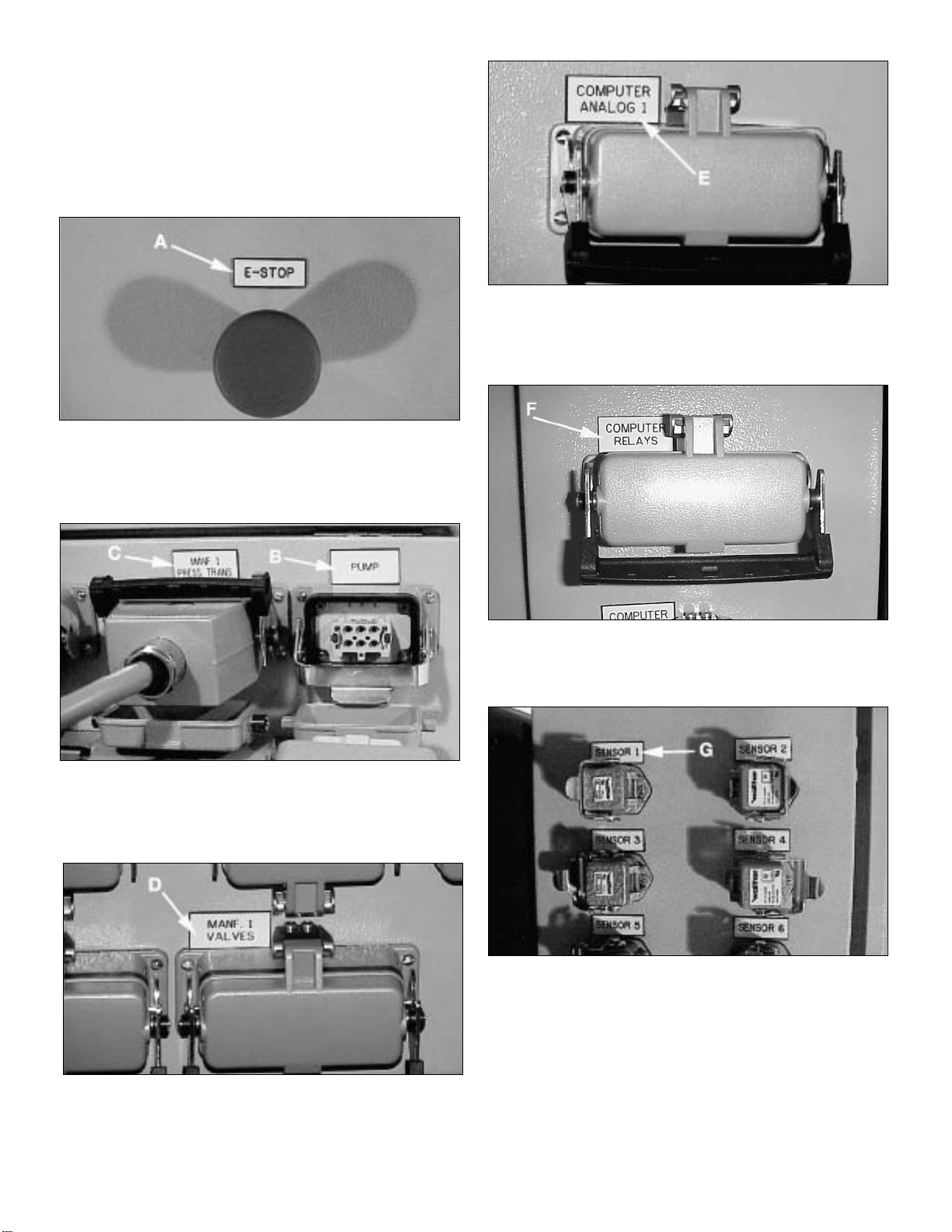
9.5 Cylinder/Sensor Interface Check
1. Sensors from each lift point should be placed near the cylinder
to ensure precise measurement of load displacement.
2. Manually extend the sensor cable to verify that the sensor
readout change corresponds to the lift point being tested. If
the cylinder and sensor operation do not correspond, the
situation must be corrected prior to operating the system.
CAUTION: Inaccurate load displacement data may be
the result of SENSORS that are not placed on solid
foundations. The display may indicate that the
sensors are seeing load movement, however, the load may
not have moved. What may occur is that the cylinder base had
settled or compressed and the sensor positions have changed
as a result.
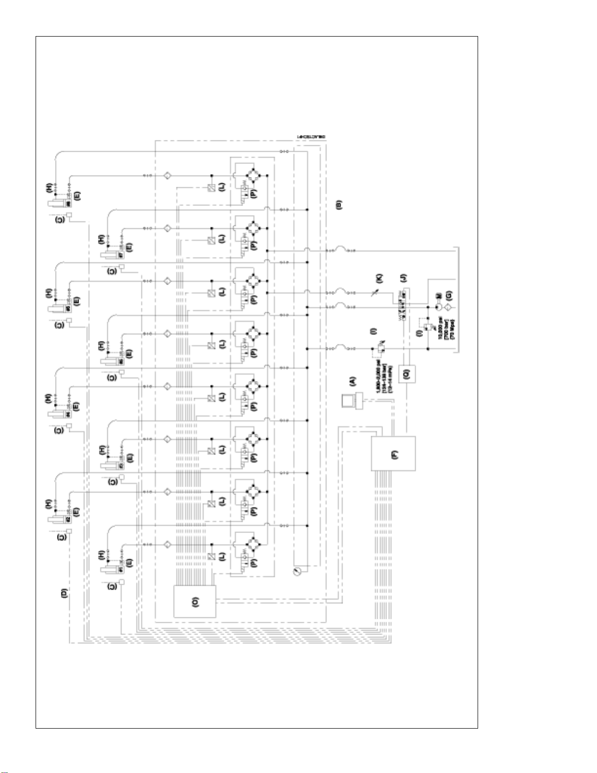
9.6 Flow Control Valve Setting
A V-8F FLOW CONTROL VALVE is located on the advance side of
the CYLINDER CONTROL VALVE. This valve is to be used to
affect the rate of flow in the extend and retract directions.This valve
is used to control the flow rate to the cylinders and can be adjusted
to increase the accuracy of the system. (Refer to "Troubleshooting
Response Errors".) For best accuracy in the lifting mode, the flow
rate must be restricted to 91 in 3/min [1,5 liter/min]) or less. The
higher the flow rate, during lifting, the lower the accuracy in
positioning.
NOTE: In the MANUAL mode, individually extend each cylinder
until the load is contacted. If the system is equipped with pressure
transducer, the pressure of each cylinder can be read on the
pressure display.When readout begins changing, the cylinder is in
contact with the load. Be sure only one cylinder is extended at a
time. Visually inspect each lift point to ensure that each cylinder
has made load contact.
10.0 LIFTING SEQUENCE
10.1 Manual Mode
To commence the cylinder movement the measuring has to be
started first by clicking the command button START.After that either
single circuits or all circuits which are switched on can be extended
or retracted. When all cylinders are driven together in the manual
mode synchronized movement is not controlled. Movement can be
stopped either by clicking the command button STOP or by hitting
any key on the keyboard (except the return or space bar key).
The info-label in the upper part of the program window shows
which function is currently used.
The display STROKE VALUE shows the movement of each lifting
point. The display DIVERGENCE shows the difference between
maximum and minimum stroke value of all circuits which are
switched on.
The system is also equipped with pressure transducers. The
pressure of each circuit can be read on the pressure display.When
readout begins changing the load is contacted. Be sure only one
cylinder is extended at a time. Visually inspect each lift point to
ensure that each cylinder has made load contact.
By clicking the command button RESET, stroke values are set to
zero. The display of the absolute sensor extension will not be
changed.
10.2 Automatic Mode - Stroke Sensing (Standard)
By choosing the AUTOMATIC option in the MODE area, automatic
mode is activated. The automatic mode allows controlled
synchronized lifting and lowering within a preset tolerance of all
lifting points which are switched on. This mode also allows for
presetting a stroke limit when lifting or lowering is stopped.
Before lifting or lowering is started all stroke values should be set
to zero by clicking the command button RESET.
The desired tolerance can be entered in the textbox TOLERANCE
after activating it by clicking on it. The minimum tolerance which
can be achieved depends on the cylinder speed which results from
the cylinder size and the output volume of the pump unit.

11
The stroke limit can be entered after clicking the appropriate
textbox. For lifting, the stroke limit has to be larger then the
maximum stroke value; for lowering, the stroke limit has to be
smaller than the minimum stroke value.
After entering tolerance and stroke limit, the movement can be
started by clicking either automatic up or automatic down.Lifting or
lowering will be stopped when the tolerance is exceeded. In this
case the reason for the deviation has to be found and eliminated.
After that, the deviation can be removed either by driving single
cylinders in the manual mode or by switching of the deviating
cylinder for a short period.
NOTE: If cylinder positions are reset to zero after lifting, the load
cannot be lowered unless a minus (-) sign is entered before the
stroke limit.
NOTE: Movement can be stopped at anytime either by clicking the
command button STOP or by hitting any key on the keyboard
(except the return or space bar key).
10.3 Automatic Mode - Stroke Step Function (Special)
The special mode is activated by clicking the appropriate control
box. This mode allows a higher accuracy of the synchronize
movement while the speed of the movement is reduced.
The operation of the program in the SPECIAL mode is similar to
the description in Section 10.1. This mode allows to enter a step
width, in addition to the above mentioned entries.The smaller this
time is chosen, the better will be the accuracy of the synchronous
movement, but the speed of the movement will decrease. Useful
step widths are between 0.1 and 0.3 sec.
10.4 Automatic Mode - Load / Pressure
Choosing the automatic mode LOAD, all activated circuits will be
operated until the first circuit has reached the preset load. It is to
be remarked, that, depending on cylinder-capacity, flow and load,
increase and decrease of the pressure might happen very quickly,
so that the preset target-value might be exceeded.
10.5 Exiting the Program and Disassembly
Before switching off the system, check that all hydraulic hose are
vented and have no pressure. If not, the appropriate circuits have
to be relieved by extending or retracting in manual mode for a short
period.
To exit the program click on the EXIT command button. After that,
exit Windows and power off the PC. After switching off the master
switch of the electric control, all electric cords, connection cords off
the displacement sensors can be uncoupled and stowed carefully.
All electric couplers have to be protected from moisture. Hydraulic
couplers have to be protected by dust caps after uncoupling.
WARNING: This system is not intended as a load
holding device. When holding a lifted load, the system
may periodically cycle the valves on/off to make up for
any leakdown which might occur. Extended periods of load
holding require blocking (cribbing) the load. Failure to do so
could result in personal injury and/or property damage.
11.0 MAINTENANCE
Refer to supplied manufacturers maintenance literature for
recommended component maintenance.

12
APPENDIX 1
TROUBLE SHOOTING GUIDE
SYMPTOM POSSIBLE CAUSE SOLUTION
Computer does not start up
No stable reading from all
sensors
No stable reading from one or a
few sensors
Reading from sensor does not
match movement of cylinders
Reading from stroke sensor
does not match reading from
pressure sensor
No operation of electro-box
No pump/motor operation
Load does not move up or down
Cylinder moving when not
selected
Error message regarding D/A or
D/O board
1. Power failure
1. Power failure
2. Emergency switch
3. Short circuit
4. Cable broken
5. Sensor defect
1. Cable broken
2. Sensor defect
1. Mismatch of circuits
1. Power failure
2. Emergency switch
1. Power failure
2.Thermal protector activated
1. Hydraulic failure
2.Valve failure
3. Relay panel defect
4.Too short steptime in special
mode
5. SELECTION ERROR
6. EMERGENCY STOP
7. Coupler not tight causing blocked
or restricted fluid movement to
cylinder
8. Defective CYLINDER CONTROL
VALVE
9. DIRECTIONAL CONTROL
VALVE will not shift
10. No signal from junction box
11. Signal present at valve plugs.
Load too heavy to lift with
advance pressure of 700 bar
(10,000psi). Retract pressure
too low to open SCK-1 CHECK
VALVES on cylinder.
1. Excessive air in the system
2. Defective SCK-1
3. Defective CYLINDER CONTROL
VALVE
4. Cylinder internal seal leakage.
5. Hydraulic hose mismatch; hose
to wrong cylinder
1. Electronics failure
1. Check cables to PC, monitor, keyboard
1. Check cables to electro-box
2. Release emergency switch
3. Check power supply in electro-box (green light). Check sensor
cables
4. Check all cables between electro-box, switchbox and PC
5. Check / replace sensors
1. Check all cables between electro-box, switchbox and PC
2. Check / replace sensors
1. Check that all sensors match the related hydraulic circuit
1. Check power supply to electro-box.
2. Release emergency switch.
1. Check power supply to motor.
2. Check power supply to motor
1. Check if all couplers are connected properly.
2. Check power supply to valves.
3. Check ref. relays activated.
4. Increase steptime.
5. Check to see if cylinders have been selected and activated.
6. EMERGENCY STOP is depressed – twist to release.
7.Tighten coupler
8. Use manual override to lower load if necessary. Depress the
pin at the center of the solenoid coil. (Refer to photo on page
7.)
9. Check for signal from CONTROLLER. If necessary, the valve
may be shifted manually by pushing the pin at the center of
the solenoid coil.
10. Replace cables. Faulty CONTROLLER CIRCUIT. Return for
service. Blown fuse in CONTROLLER. – REPLACE.
11. Replace valve. Revisit load calculations – possibly use larger
cylinders or more cylinders. Check retract pressure and reset
to 124 – 138 bar (1800 – 2000 psi).
1. Bleed air out of system.
2. Replace
3. Replace
4. Replace seals or cylinder.
5. Correct hose routing.
1. Contact Enerpac to replace D/A or D/O board.

13
APPENDIX 1
continued… TROUBLE SHOOTING GUIDE
SYMPTOM POSSIBLE CAUSE SOLUTION
Out of tolerance too often
Keyboard or mouse not working
Leaky coupler
Leaky hydraulic fitting
1. High speed, dynamic effects
2. Air in hydraulic system
1. Keyboard or mouse disconnected
1. Defective o-ring
1. Loose connection
1. Reduce flow from pump using V66F/V8F.Verify that the correct
CYLINDER CONTROL VALVE is matched with the correct
SENSOR. Hoses reversed – Check hydraulic plumbing to
cylinder. Cylinder sinking into foundation. Must have solid
foundation to prevent settling. Nature’s influence – postpone lift
until natural phenomenon subsides.
2. Bleed system.To bleed system, refer to CYLINDER
CONTROL CHECK, section 9.4.
1. Finish or stop operation safely, reconnect keyboard or mouse,
reboot PC
1. Replace o-ring
1. Use Teflon tape and retighten

14
APPENDIX 2
GRAPHIC USER INTERFACE DISPLAYS
Cylinder Stroke Readout
Cylinder Pressure Readout
Absolute Displacement Sensor Readout
Data Storage
System Stop / Start
Reset Stroke Values
to Zero
Manual Mode
Automatic Mode
Load/Pressure
Automatic Mode
Stroke Sensing
Actual Tolerance
System is Holding
Difference between Min. and Max.
Stroke Values for Active Cylinders.
System Stop
System Start
Desired Tolerance Value
Desired Stroke
Value
Special Stroke Step Function
Active Cylinder Indicator
Green "ON"
Red "OFF"
Cylinder Activation Button
Lower LoadRaise Load

Fiche d’instructions
Système De Levage Synchrone Informatisé
15
1.0 INSTRUCTIONS IMPORTANTES RELATIVES
À LA RÉCEPTION
Inspecter tous les composants pour vous assurer qu’ils n’ont subi
aucun dommage en cours d’expédition. Les dommages subis en
cours de transports ne sont pas couverts par la garantie. S’il sont
abîmés, aviser immédiatement le transporteur, qui est responsable
des frais de réparation et de remplacement résultant de
dommages en cours de transport.
LA SÉCURITÉ AVANT TOUT !
2.0 SÉCURITÉ
Lire attentivement toutes les instructions et mises en
garde et tous les avertissements. Suivre toutes les
précautions pour éviter d’encourir des blessures
personnelles ou de provoquer des dégâts matériels durant le
fonctionnement du système. Enerpac ne peut pas être tenue
responsable de dommages ou blessures résultant de l’utilisation
risquée du produit, d’un mauvais entretien ou d’une application
incorrecte du produit et du système. En cas de doute sur les
précautions ou les applications, contacter Enerpac. En l’absence
d’une formation aux mesures de sécurité à prendre en présence de
liquides sous haute pression, consulter un centre de distribution ou
de réparation Enerpac pour suivre un cours gratuit sur ce thème.
Respecter les mises en garde et avertissements suivants sous
peine de provoquer des dégâts matériels et des blessures
personnelles.
Une mise en garde ATTENTION sert à indiquer des procédures
d’utilisation et de maintenance correctes qui visent à empêcher
l’endommagement voire la destruction du matériel ou d’autres
dégâts.
Un AVERTISSEMENT indique un danger potentiel qui exige la
prise de mesures particulières visant à écarter tout risque de
blessure.
La mention DANGER n’est utilisée que lorsqu’une action ou un
acte de négligence risque de causer des blessures graves, voire
mortelles.
AVERTISSEMENT : Porter un équipement de
protection personnelle adéquat pour utiliser un
appareil hydraulique.
AVERTISSEMENT : Rester à l’écart de charges
soutenues par un mécanisme hydraulique. Un vérin,
lorsqu’il est utilisé comme monte-charge, ne
doit jamais servir de support de charge. Après avoir
monté ou abaissé la charge, elle doit être bloquée par un
moyen mécanique.
AVERTISSEMENT: UTILISER SEULEMENT DES PIÈCES
RIGIDES POUR SOUTENIR LES CHARGES.
Sélectionner avec précaution des blocs d’acier ou de
bois capables de supporter la charge. Ne jamais utiliser un
vérin hydraulique comme cale ou intercalaire d’appui pour les
applications de levage ou de pressage.
DANGER : Pour écarter tout risque de blessure
personnelle, maintenir les mains et les pieds à
l’écart du vérin et de la pièce à usiner durant
l’utilisation.
AVERTISSEMENT : Ne pas dépasser les valeurs
nominales du matériel. Ne jamais essayer de soulever
une charge d’un poids supérieur à la capacité du
vérin. Une surcharge entraînera la panne du matériel et
risque de provoquer des blessures personnelles. Les vérins
sont conçus pour une pression maximale de 700 bar. Ne pas
connecter de cric ou de vérin à une pompe affichant une
pression nominale supérieure.
Ne jamais régler la soupape de sûreté à une pression
supérieure à la pression nominale maximale de la
pompe sous peine de provoquer des dégâts matériels
et/ou des blessures personnelles.
AVERTISSEMENT : La pression de fonctionnement du
système ne doit pas dépasser la pression nominale du
composant du système affichant la plus petite valeur.
Installer des manomètres dans le système pour surveiller la
pression de fonctionnement. Ils permettent de vérifier ce qui
se passe dans le système.
L2543 Rev. O 08/01
Table Des Matières. . . . . . . . . . . . . . . . . . . Page
Instructions De Réception Importantes . . . . . . . 15
La Sécurité D’abord – Questions De Sécurité . . 15
Description Générale. . . . . . . . . . . . . . . . . . . . 16
Schéma Du Circuit (Vérins A Double Effet) . . . 17
Schéma Du Circuit (Vérins A Effet Simple). . . . 18
Spécifications Des Eléments Electriques. . . . . . 19
Sélection Des Eléments Hydrauliques. . . . . . . . 19
Affichage De L’écran Et Fonctions Du Contrôleur
. 20
Configuration Du Système . . . . . . . . . . . . . . . . 20
Montage Des Eléments Hydrauliques . . . . . . . . 21
Montage Des Eléments Electriques . . . . . . . . . 21
Mise Sous Tension Du Système Et Vérification
Des Commandes . . . . . . . . . . . . . . . . . . . . . . . 22
Montage Et Démarrage . . . . . . . . . . . . . . . . . 22
Réglage Et Options . . . . . . . . . . . . . . . . . . . . 23
Page
Stockage Et Récupération Des Données . . . . 23
Vérification Du Pilotage Des Vérins . . . . . . . . 23
Vérification De L’interface Des Capteurs Des
Vérins . . . . . . . . . . . . . . . . . . . . . . . . . . . . . . 24
Réglage Du Régulateur De Débit . . . . . . . . . . 24
Session De Levage. . . . . . . . . . . . . . . . . . . . . . 24
Mode Manuel . . . . . . . . . . . . . . . . . . . . . . . . 24
Mode Automatique-Détection De Course
(Standard) . . . . . . . . . . . . . . . . . . . . . . . . . . . 24
Mode Automatique-Fonction Echelon De
Course (Spécial) . . . . . . . . . . . . . . . . . . . . . . 25
Charge/Pression En Mode Automatique. . . . . 25
Sortie Du Programme Et Démontage . . . . . . . 25
Entretien. . . . . . . . . . . . . . . . . . . . . . . . . . . . . . 25
Annexe 1 – Guide De Dépannage . . . . . . . . 26-27
Annexe 2 – Affichages En Entrée Du Contrôleur
. . 28

16
ATTENTION : Éviter d’endommager les tuyaux
hydrauliques. Éviter de les plier et de les tordre en les
mettant en place. Un tuyaux plié ou tordu entraînera
un fort retour de pression. Les plis et coudes prononcés
endommageront par ailleurs l’intérieur du tuyaux, provoquant
son usure précoce.
Ne pas faire tomber d’objets lourds sur le tuyaux.
Un fort impact risque de causer des dégâts
intérieurs (torons métalliques). L’application d’ une
pression sur un tuyaux endommagé risque d’entraîner sa
rupture.
IMPORTANT : Ne pas soulever le matériel hydraulique
en saisissant ses tuyaux ou ses raccords articulés.
Utiliser la poignée de transport ou procéder d’une
autre manière sûre.
ATTENTION : Garder le matériel
hydraulique à l’écart de flammes et d’une source de
chaleur. Une forte température
amollira les garnitures et les joints et
provoquera par conséquent des fuites. La
chaleur affaiblit également les matériaux et
les garnitures du tuyaux. Pour une
performance maximale, ne pas exposer le
matériel à une température supérieure ou
égale à 65 °C [150 °F]. Protéger tuyaux et
vérins de projections de soudure.
DANGER : Ne pas manipuler les
tuyaux sous pression. L’huile sous
pression qui risque de s’en
échapper peut pénétrer dans la peau et
provoquer des blessures graves. En cas
d’injection d’huile sous la peau, contacter
immédiatement un médecin.
AVERTISSEMENT : Utiliser des
vérins hydrauliques uniquement
dans un système couplé. Ne
jamais utiliser un vérin en présence de
raccords déconnectés. La surcharge du
vérin peut avoir des effets désastreux sur
ses composants, qui peuvent causer des
blessures graves.
AVERTISSMENT : S'assurer de la stabilité de
l'ensemble avant de lever une charge. Le vérin doit
être placé sur une surface plane capable de supporter
la charge. Lorsqu'applicable, utiliser une base de vérin
pour accroître la stabilité. Ne pas souder ou modifier le vérin
de quelque façon que ce soit pour y fixer une base ou un autre
dispositif de support.
Éviter les situations où les charges ne sont pas
directement centrées sur le piston du vérin. Les
charges décentrées imposent un effort considérable
au vérins et pistons. En outre, la charge risque de glisser ou
de tomber, ce qui crée un potentiel de danger.
Répartir la charge uniformément sur toute la surface
d'appui. Toujours utiliser un coussinet d'appui si des
accessoires non filetés sont utilisés.
IMPORTANT : Le matériel hydraulique doit
uniquement être réparé par un technicien hydraulique
qualifié. Pour toute réparation, contacter le centre de
réparation ENERPAC agréé le plus proche. Pour assurer la
validité de la garantie, n’utiliser que de l’huile ENERPAC.
AVERTISSEMENT : Remplacer immédiatement les
pièces usées ou endommagées par des pièces
ENERPAC authentiques. Les pièces de qualité
standard se casseront et provoqueront des blessures et des
dégâts matériels. Les pièces ENERPAC sont conçues pour
s’ajuster parfaitement et résister à de fortes charges.
3.0 DESCRIPTION GÉNÉRALE
Le système de levage synchrone Enerpac est un système
assurant un contrôle de position précis pour le levage et
l’abaissement d’objets de tonnage élevé. Le contrôleur informatisé
reçoit des signaux électroniques provenant de capteurs de
position de charge fixés sur celle-ci, à proximité de chaque vérin.
Le logiciel du contrôleur traite ces informations et envoie des
signaux aux distributeurs pilotant chaque vérin.L’ouverture et/ou la
fermeture des distributeurs selon le besoin, lève ou abaisse la
charge de façon uniforme et dans les limites des paramètres de
précision définis par l’utilisateur.
Le système de levage synchrone informatisé
Enerpac consiste en les éléments standards
décrit ci-dessous. Voir les Figures 1 et 2 pour
la présentation d’un système de levage à huit
points type.
3.1 Éléments Standards
A: CONTRÔLEUR (SLCPC-2001)
L’utilisateur sélectionne les paramètres de
levage et contrôle un maximum de vingt-quatre
points de levage grâce au CONTRÔLEUR.
B: COLLECTEUR DES DISTRIBUTEURS
(SLVS-8)
Le CHARIOT DE COLLECTEUR DES
DISTRIBUTEURS maintient le collecteur qui
reçoit les signaux de marche/arrêt provenant
du contrôleur. Les distributeurs s’ouvrent et se
ferment, contrôlant le débit aux vérins lorsqu’ils
se déploient, ou contrôlant le débit provenant
des vérins lorsqu’ils se rétractent, et déplaçant
la charge d’une façon synchrone et contrôlée
tout en assurant la précision souhaitée par
l’utilisateur.
C: CAPTEUR DE DÉPLACEMENT (SLSS-500, 1000, ou 2000)
Le CAPTEUR contient des éléments électroniques qui
détectent le déplacement de la charge.
D:
CABLE DE CAPTEUR (SLSC-50 et SLEC-50)
Le CABLE DE CAPTEUR transmet les signaux en retour des
capteurs au CONTRÔLEUR.
E: ENSEMBLE DE CLAPET ANTI-RETOUR (SCK-1)
Le CLAPET ANTI-RETOUR PILOTÉ (SCK-1) assure une
marge de sécurité supplémentaire de maintien de la charge en
cas de défaillance d’un tuyaux ou d’alimentation. Le CLAPET
ANTI-RETOUR PILOTÉ (SCK-1) est conçu pour être utilisé
avec des VÉRINS HYDRAULIQUES à double effet.
F: BOÎTIER ÉLECTRIQUE (SLEB-8, SLEB-16 ou SLEB-24)
Le BOÎTIER ÉLECTRIQUE reçoit les tensions en sortie de
commande des distributeurs provenant du CONTRÔLEUR et
les distribue aux DISTRIBUTEURS DES VÉRINS appropriés,
déployant ou rétractant ces vérins selon le besoin pour contrôler
les fonctions de levage ou d’abaissement.
IMPORTANT : le SYSTÈME
DE LEVAGE SYNCHRONE
INFORMATISÉ ENERPAC est
un système de contrôle de
position de précision
pouvant être utilisé dans un
large éventail d’applications.
S’assurer que les éléments
fournis par l’utilisateur sont
compatibles. Tous les
utilisateurs doivent lire et
bien comprendre ce manuel
d’utilisation avant d’utiliser
le matériel.

17
Figure 1, Système De Levage A Huit Points Avec Vérins A Double Effet
A: Contrôleur, SLCPC-2001
B : Collecteur de distributeur, SLVS-8
C : Capteur de déplacement, SLSS-500, 1000 ou 2000
D : Câble de capteur, SLSC-10 et SLSC-50
E : Ensemble de clapet anti-retour, SCK-1
F : Boîtier électrique, SLEB-8, 16 ou 24
G : Pompe hydraulique
H : Vérin hydraulique
I : Soupape de sécurité
J : Distributeur directionnel
K : Régulateur de débit
L : Capteur de pression
O : Boîtier de raccordement – collecteur
P : Distributeur de vérin
Q : Boîtier de raccordement – soupape de pompe

18
A: Contrôleur, SLCPC-2001
B : Collecteur de distributeur, SLVS-8
C : Capteur de déplacement, SLSS-500, 1000 ou 2000
D : Câble de capteur, SLSC-10 et SLSC-50
F : Boîtier électrique, SLEB-8, 16 ou 24
G : Pompe hydraulique
H : Vérin hydraulique
I : Soupape de sécurité
J : Distributeur directionnel
K : Régulateur de débit
L : Capteur de pression
M : Fusible de vitesse, VF-1
N : Soupape d’aspiration (facultative)
O : Boîtier de raccordement – collecteur
P : Distributeur de vérin
Q : Boîtier de raccordement – soupape de pompe
Figure 2, Système De Levage A Huit Points Avec Vérins A Effet Simple

19
G: POMPE HYDRAULIQUE
La POMPE HYDRAULIQUE fournit le débit aux VÉRINS
HYDRAULIQUES et leur permet de se déployer ou de se
rétracter. Le DISTRIBUTEUR DIRECTIONNEL monté sur
collecteur est piloté par le CONTRÔLEUR.
H: VÉRIN HYDRAULIQUE
Le VÉRIN HYDRAULIQUE lève ou abaisse la charge.
I: SOUPAPES DE SÉCURITÉ
Les SOUPAPES DE SÉCURITÉ réglables contrôlent la
pression maximale du système dans les circuits de
déploiement et de retrait.
J: DISTRIBUTEUR DIRECTIONNEL
Le DISTRIBUTEUR DIRECTIONNEL monté sur collecteur
contrôle les débits de déploiement et de retrait du fluide
hydraulique et est piloté par le système.
K: RÉGULATEUR DE DÉBIT
Le RÉGULATEUR DE DÉBIT contrôle la vitesse de
déploiement et de retrait des VÉRINS HYDRAULIQUES.
L: CAPTEUR DE PRESSION
Le CAPTEUR DE PRESSION permet à l’utilisateur de
contrôler les pressions du système.
M: FUSIBLE DE VITESSE (VF-1)
Le FUSIBLE DE VITESSE assure une marge de sécurité
supplémentaire de maintien de la charge en cas de défaillance d’un
tuyaux ou d’alimentation.Le FUSIBLE DEVITESSE est conçu pour
être utilisé avec des VÉRINS HYDRAULIQUES à simple effet.
N: SOUPAPE D’ASPIRATIO
La SOUPAPE D’ASPIRATION est utilisée pour faciliter le retour
du fluide hydraulique du VÉRIN HYDRAULIQUE au réservoir
de la POMPE HYDRAULIQUE..
REMARQUE : il s’agit des principaux éléments requis pour
l’utilisation d’un système de deux à huit points de levage. Des
éléments supplémentaires sont requis pour plus de points de
levage. Contacter Enerpac pour assistance lors de la
sélection des éléments.
4.0 SPÉCIFICATIONS DES ÉLÉMENTS ÉLECTRIQUES
(VOIR LES TABLEAUX)
ATTENTION : le BOÎTIER ÉLECTRIQUE est conçu pour
être résistant à l’eau mais n’est pas étanche. Lors du
stockage de l’unité, toujours utiliser les bouchons de
protection fournis pour tous les connecteurs. Le
CONTRÔLEUR est du matériel électronique sensible et ne doit
pas être soumis à un choc violent.
ATTENTION :le CAPTEUR est également conçu pour être
résistant à l’eau mais n’est pas étanche (voir la Figure 10).
Ne pas l’immerger dans du liquide. Le CAPTEUR contient
du matériel électronique sensible et ne doit pas être soumis à un
choc violent, en le laissant tomber ou en laissant le cordon de
course revenir brutalement dans le logement du capteur.
AVERTISSEMENT : le contrôleur, le moniteur et le
boîtier électronique doivent être raccordés à la même
alimentation avec prise de terre.
CONTRÔLEUR : SLCPC-2001
Plage de température de service : 0 °C à 60 °C (32 °F à 140 °F)
Plage de température de stockage : 0 °C à 60 °C (32 °F à 140 °F)
Alimentation requise : 120/230 V CA monophasé, 50/60 Hz.
Dimensions physiques : 457,2 mm (18 po)x457,2 mm (18 po) x 203,2 mm (8 po)
Poids : 16 kg (40 lb)
DISTRIBUTEUR DE VÉRIN
N° de Modèle Alimentation Pression
SLVS-8 24 V CC 700 bar (10 000 psi)
VSP424 24 V CC 700 bar (10 000 psi)
5.0 SÉLECTION DES ÉLÉMENTS HYDRAULIQUES
5.1 Vitesse De Levage/Descente Recommandée
Lors de la sélection des éléments hydrauliques (pompe et vérins),
il est important de savoir que la vitesse des vérins est aux dépens
de la précision de levage. Plus le vérin se déplace rapidement,
plus il est difficile de maintenir la précision programmée. De façon
idéale, la pompe et les vérins peuvent être sélectionnés afin que
la vitesse de levage maximale ne soit pas supérieure à 7,5 cm/mn
(3 po/mn) lorsque tous les vérins sont activés.
Calcul de la vitesse de levage :
Q/A = VITESSE DES VÉRINS, cm (mn) (po/mn)
où Q = débit de la pompe (cm3/mn [po3/mn])
A = somme des surface effectives des vérins (cm2[po2])
ATTENTION : le débit devant être fortement restreint,
la température de l’huile peut éventuellement
augmenter au-delà des niveaux acceptables. Un
refroidisseur d'huile et/ou réservoir de pompe plus grands
doivent être envisagés pour des levages de longue durée. La
température de l’huile ne doit pas être supérieure à 65 °C (150
°F). Par temps froid, en dessous de 0 °C (32 °F), l’huile
hydraulique s’épaissit et ralentit la réaction du système.
Consulter Enerpac pour les modifications du système
permettant d’améliorer les performances par temps froid.
BOÎTIER ÉLECTRIQUE : SLEB-8, 16, oU 24
Plage de température de service : 0 °C à 60 °C (32 °F à 140 °F)
Plage de température de stockage : 0 °C à 60 °C (32 °F à 140 °F)
Alimentation requise : 120/230 V CA monophasé, 50/60 Hz, 750 VA
Dimensions physiques : 914,4 mm (36 po)x609,0 mm (24 po) x 177,8 mm (7 po)
Poids : 68 kg (150 lb)
CAPTEUR : SLSS-500, 1000, ou 2000
Étendue de mesure : 0-2000 mm (0-78.74 po) de rallonge de cordon
Précision : ± 0,1 % de la course (± 1 mm ou 0.040 po pour le plein déploiement)
Plage de température de service : 0 °C à 60 °C (32 °F à 140 °F)
Plage de température de stockage : -17.78 °C à 60 °C (-17 °C à 140 °F)
Dimensions physiques : 93 mm (3.6 po) x 50 mm (1.9 po) x 50 mm (1.9 po)
Poids : 0,8 kg (1.7 lb) maxi
SPÉCIFICATIONS DES ÉLÉMENTS ÉLECTRIQUES

20
La conception modulaire du SYSTÈME DE LEVAGE
SYNCHRONE ENERPAC permet de minimiser les coûts pour les
clients qui disposent déjà de matériel hydraulique requis pour le
levage. Lors de la sélection des éléments, il est important de
garder à l’esprit que le système est conçu pour une pression de
service maximale de 700 bar (10 000 psi). Les vérins doivent être
sélectionnés de façon à ce qu’ils puissent lever la charge à une
pression de service de 138-552 bar (2 000-8 000 psi) afin de
garder une pression de réserve pour maîtriser les déplacements
de charge possibles d’un vérin à l’autre.
AVERTISSEMENT : tous les vérins doivent comporter
un dispositif de maintien de charge. Ce dispositif peut
être soit mécanique, comme un calage externe, soit
hydraulique, comme l’ENSEMBLE DE CLAPET ANTI-RETOUR
Enerpac SCK-1. Un clapet anti-retour est fortement
recommandé pour des raisons de sécurité : en cas de
défaillance de tuyaux hydraulique, le vérin se verrouille de
façon hydraulique et empêche ainsi la charge de tomber sans
contrôle. Un fusible de vitesse en ligne, VF-1, peut également
remplacer le SCK-1 en cas d’espace restreint ; le SCK-1 reste
cependant le dispositif de verrouillage hydraulique conseillé.
Le calage externe est requis lorsque qu’un maintien et un
positionnement en extension de la charge sont requis.
L’absence d’un dispositif de maintien de la charge à chaque
vérin peut provoquer des blessures et/ou des dégâts matériels
catastrophiques.
Une pompe Enerpac équipée d’un DISTRIBUTEUR
DIRECTIONNEL activé par solénoïde VSP-424 peut être utilisée
avec ce système. Le DISTRIBUTEUR DIRECTIONNEL
sélectionne la fonction de sortie/retrait des vérins et est sous
la direction et le pilotage du CONTRÔLEUR SLCPC-2001. La
mise en marche/arrêt de la pompe est contrôlée
manuellement. Un distributeur à 4 voies déporté et activé par
solénoïde (VSPR-424) peut être utilisé afin d’adapter d’autres
pompes Enerpac au système.
6.0 AFFICHAGE DE L’ÉCRAN ET FONCTIONS DU
CONTRÔLEUR
Boîtier électrique SLEB-8, 16 ou 24
• Commutateur de déconnexion
Déconnecte l’alimentation à tous les éléments du boîtier électrique,
les appareils hydrauliques, les capteurs et les capteurs de course.
(Arrête tout pilotage et mouvement.)
• Bouton d’arrêt d’urgence rouge
Arrête tout pilotage et mouvement.
• Bouton lumineux de mise sous tension
Met les éléments de contrôle du boîtier électrique sous tension.
• Lampe témoin de tension
Indique que les éléments de contrôle du boîtier électrique sont sous
tension et que le boîtier électrique est prêt à fonctionner.
Sélections d’affichage : (Annexe 2)
Arrêt Auto (course)
Marche Auto (charge)
Réinitialisation Manuel
Quitter Activer les circuits
Protocole de données Contrôle manuel
Descente
ATTENTION : lors de l’utilisation en mode MANUEL,
l’utilisateur n’a que le contrôle de marche/arrêt des vérins.
La synchronisation des vérins n’est pas possible en mode
MANUEL.
7.0 SYSTÈME REQUIS
Avant la configuration du système, tous les vérins équipé d’un
ENSEMBLE DE CLAPET ANTI-RETOUR SCK-1 doivent comporter
un tuyaux hydraulique Enerpac avec un coupleur raccordant la
conduite pilote du clapet anti-retour à la conduite de retrait du vérin.
Des tubes en acier de Ø ext. 9,5 mm (3/8 po) ou 6,4 mm (1/4 po)
(conduite pilote de clapet anti-retour), découpés et formés pour les
adapter au vérin choisi peuvent être utilisés. Les tubes et le tuyaux
doivent pouvoir supporter une pression de service de 350 bar (5 000
psi), uniquement sur le côté retrait du vérin.
Avant la configuration du système, tous les vérins équipé d’un
ENSEMBLE DE CLAPET ANTI-RETOUR SCK-1 doivent comporter
un tuyaux hydraulique Enerpac avec un coupleur raccordant la
conduite pilote du clapet anti-retour à la conduite de retrait du vérin.
Des tubes en acier de Ø ext. 9,5 mm (3/8 po) ou 6,4 mm (1/4 po)
(conduite pilote de clapet anti-retour), découpés et formés pour les
adapter au vérin choisi peuvent être utilisés. Les flexibles et
tuyauteries doivent pouvoir supporter une pression de service de
350 bar (5 000 psi), uniquement sur le côté retrait du vérin.
AVERTISSEMENT: ne jamais installer de logiciel
supplémentaire sur l’ordinateur pour ne pas
endommager ou influencer le logiciel de levage
synchrone. ENERPAC n’assume aucune responsabilité quant
aux dégâts ou fonctionnement accidentel du système de
levage synchrone si le fichier de levage synchrone est affecté
par un autre logiciel.
IMPORTANT : utiliser des raccords rapides Enerpac
sur les flexibles, les collecteurs et les appareils
hydrauliques afin de faciliter le montage et
démontage rapides du système. Aucune saleté ou autre
contaminant ne doit se trouver sur les raccords lors du
montage. Des contaminants dans l’huile hydraulique peuvent
endommager les éléments hydrauliques sensibles.
ATTENTION: il est recommandé de calculer la
pression de service de chaque vérin avant de
commencer le levage. La première étape consiste en
un essai de mise sous pression d’un vérin (vérin par vérin)
avec une certaine surcharge (110 - 125 % de la charge
calculée) afin de s’assurer que les surfaces sur lesquelles sont
placés les vérins peuvent supporter la charge. Cette opération
est facilement effectuée à l’aide du mode « automatic (load)
[automatique (charge)] ». Une fois le levage commencé,
vérifier la pression (charge) de tous les circuits.
IMPORTANT: faire monter et descendre les vérins
plusieurs fois pour chasser l’air du système. Une fois
l’air purgé du système, vérifier la base des vérins afin
de s’assurer d’une surface d’appui stable et ferme. Déployer
chaque cylindre (un à la fois) à la pression maximale, sans
lever la charge. Vérifier l’absence de fentes, d’enfoncement de
vérin ou de surface d’appui irrégulière sous la base.
This manual suits for next models
1
Table of contents
Languages:
Other Enerpac Lifting System manuals
Popular Lifting System manuals by other brands

Lippert Components
Lippert Components ground control 3.0 user manual

HAUVREX
HAUVREX HXL6128 Operation & maintenance manual

OMA
OMA 528C Instruction manual for using and maintaining

Reechcraft
Reechcraft PowerLift PL53 Operators safety manual

Audipack
Audipack DWS-120 E Mounting/user instruction

Mondial Designs Limited
Mondial Designs Limited GP-9 Installation, operation & maintenance manual