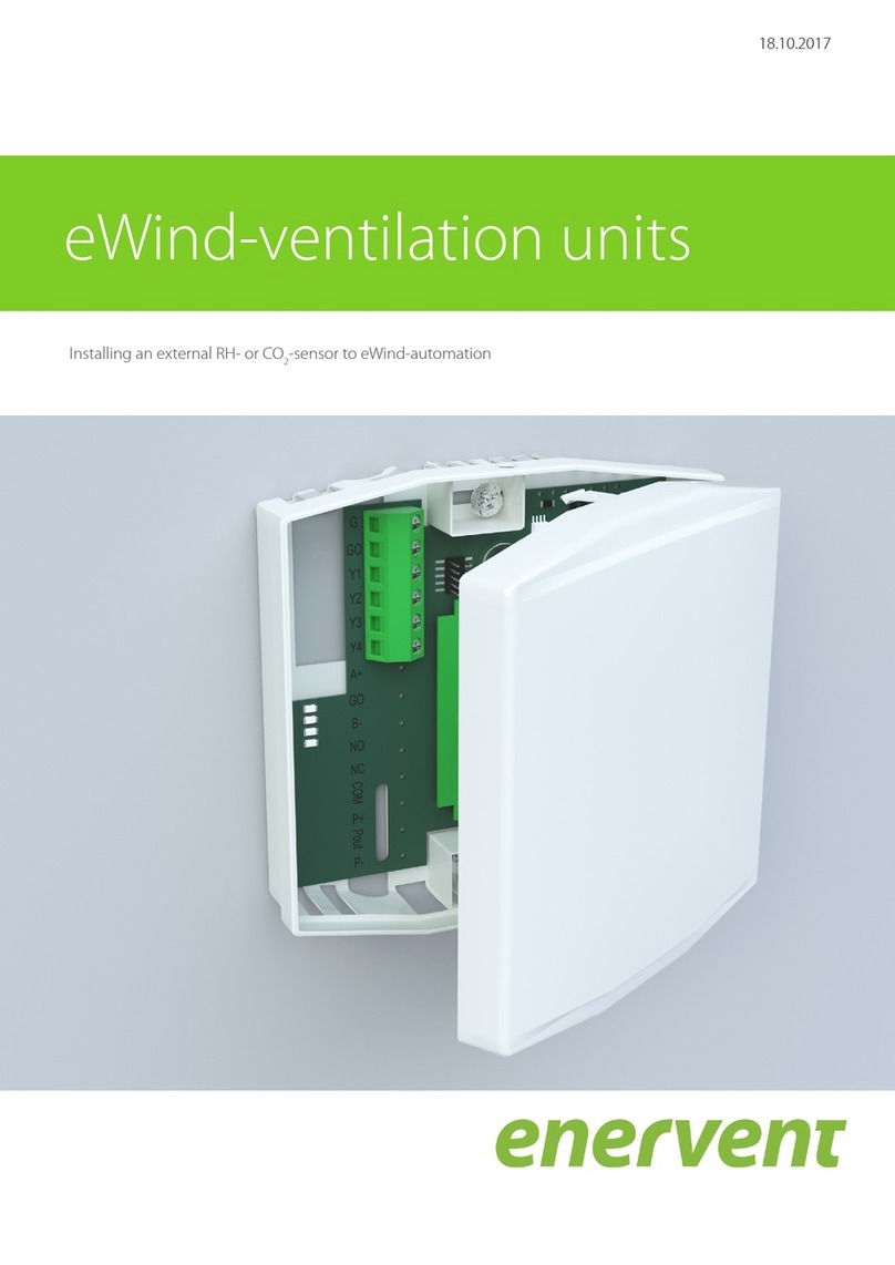
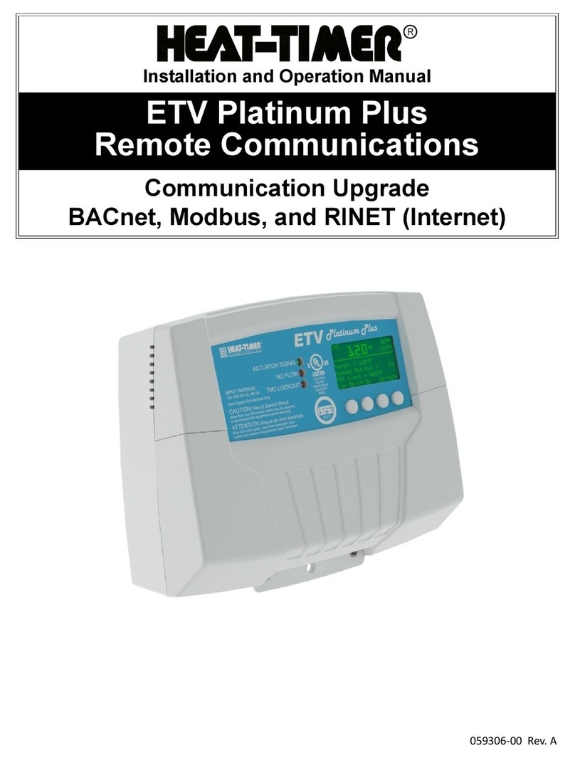
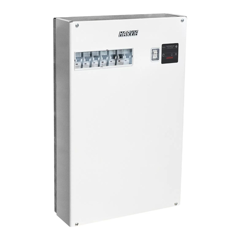
enervent eWind User manual

User instructions
ENG
25.01.2016
Enervent eWind

2
Copyright © Ensto Enervent 2016.
Unauthorized copying and lending are prohibited.
Approvals and version history
Revision Date Description of change Approved by
0.0 2016-01-25

3User instructions
EN
Contents
Approvals and version history . . . . . . . . . . . . . . . . . . . . . . . . . . . . . . . . . . . . . . . . . . . . . . . . . . . . . . . . . . . . . . . . . . . . . . . . . . . . . . . . . . . . . . . . . . . . . . . . . . . .2
READ ME FIRST...................................................................................................................4
Setting up the system . . . . . . . . . . . . . . . . . . . . . . . . . . . . . . . . . . . . . . . . . . . . . . . . . . . . . . . . . . . . . . . . . . . . . . . . . . . . . . . . . . . . . . . . . . . . . . . . . . . . . . . .4
INTENDED USE...................................................................................................................4
OPERATION ......................................................................................................................4
USING VENTILATION UNIT . . . . . . . . . . . . . . . . . . . . . . . . . . . . . . . . . . . . . . . . . . . . . . . . . . . . . . . . . . . . . . . . . . . . . . . . . . . . . . . . . . . . . . . . . . . . . . . . . . . . . . . .5
eWind control panel. . . . . . . . . . . . . . . . . . . . . . . . . . . . . . . . . . . . . . . . . . . . . . . . . . . . . . . . . . . . . . . . . . . . . . . . . . . . . . . . . . . . . . . . . . . . . . . . . . . . . . . . . .5
Every day use of ventilation. . . . . . . . . . . . . . . . . . . . . . . . . . . . . . . . . . . . . . . . . . . . . . . . . . . . . . . . . . . . . . . . . . . . . . . . . . . . . . . . . . . . . . . . . . . . . . . . . . .6
Operation modes . . . . . . . . . . . . . . . . . . . . . . . . . . . . . . . . . . . . . . . . . . . . . . . . . . . . . . . . . . . . . . . . . . . . . . . . . . . . . . . . . . . . . . . . . . . . . . . . . . . . . . . . . . . .6
Away mode (1) ...............................................................................................................6
Home mode (2) ..............................................................................................................6
Home mode with boosted ventilation (3) . . . . . . . . . . . . . . . . . . . . . . . . . . . . . . . . . . . . . . . . . . . . . . . . . . . . . . . . . . . . . . . . . . . . . . . . . . . . . . . . . . . . .6
Boost mode (4)...............................................................................................................6
Changing supply air temperature . . . . . . . . . . . . . . . . . . . . . . . . . . . . . . . . . . . . . . . . . . . . . . . . . . . . . . . . . . . . . . . . . . . . . . . . . . . . . . . . . . . . . . . . .6
Overpressure (replace) mode . . . . . . . . . . . . . . . . . . . . . . . . . . . . . . . . . . . . . . . . . . . . . . . . . . . . . . . . . . . . . . . . . . . . . . . . . . . . . . . . . . . . . . . . . . . . . . . .7
Heating mode. . . . . . . . . . . . . . . . . . . . . . . . . . . . . . . . . . . . . . . . . . . . . . . . . . . . . . . . . . . . . . . . . . . . . . . . . . . . . . . . . . . . . . . . . . . . . . . . . . . . . . . . . . . . . . . .7
Eco mode ....................................................................................................................7
USING VENTILATION EFFICIENTLY . . . . . . . . . . . . . . . . . . . . . . . . . . . . . . . . . . . . . . . . . . . . . . . . . . . . . . . . . . . . . . . . . . . . . . . . . . . . . . . . . . . . . . . . . . . . . . . . .7
Using ventilation in cold season . . . . . . . . . . . . . . . . . . . . . . . . . . . . . . . . . . . . . . . . . . . . . . . . . . . . . . . . . . . . . . . . . . . . . . . . . . . . . . . . . . . . . . . . . . . . . .8
ENHANCED FEATURES. . . . . . . . . . . . . . . . . . . . . . . . . . . . . . . . . . . . . . . . . . . . . . . . . . . . . . . . . . . . . . . . . . . . . . . . . . . . . . . . . . . . . . . . . . . . . . . . . . . . . . . . . . . .8
Information view. . . . . . . . . . . . . . . . . . . . . . . . . . . . . . . . . . . . . . . . . . . . . . . . . . . . . . . . . . . . . . . . . . . . . . . . . . . . . . . . . . . . . . . . . . . . . . . . . . . . . . . . . . . . .8
eWind Info list. . . . . . . . . . . . . . . . . . . . . . . . . . . . . . . . . . . . . . . . . . . . . . . . . . . . . . . . . . . . . . . . . . . . . . . . . . . . . . . . . . . . . . . . . . . . . . . . . . . . . . . . . . . .8
Measurements view . . . . . . . . . . . . . . . . . . . . . . . . . . . . . . . . . . . . . . . . . . . . . . . . . . . . . . . . . . . . . . . . . . . . . . . . . . . . . . . . . . . . . . . . . . . . . . . . . . . . . . . . . .9
eWind Measurements list . . . . . . . . . . . . . . . . . . . . . . . . . . . . . . . . . . . . . . . . . . . . . . . . . . . . . . . . . . . . . . . . . . . . . . . . . . . . . . . . . . . . . . . . . . . . . . . . .9
Service reminder view. . . . . . . . . . . . . . . . . . . . . . . . . . . . . . . . . . . . . . . . . . . . . . . . . . . . . . . . . . . . . . . . . . . . . . . . . . . . . . . . . . . . . . . . . . . . . . . . . . . . . . . .9
Time to service . . . . . . . . . . . . . . . . . . . . . . . . . . . . . . . . . . . . . . . . . . . . . . . . . . . . . . . . . . . . . . . . . . . . . . . . . . . . . . . . . . . . . . . . . . . . . . . . . . . . . . . . . . .9
Settings view .............................................................................................................. 10
ADJUSTMENTS................................................................................................................. 10
Supply air is too warm. . . . . . . . . . . . . . . . . . . . . . . . . . . . . . . . . . . . . . . . . . . . . . . . . . . . . . . . . . . . . . . . . . . . . . . . . . . . . . . . . . . . . . . . . . . . . . . . . . . . . . 10
Supply air is too cold . . . . . . . . . . . . . . . . . . . . . . . . . . . . . . . . . . . . . . . . . . . . . . . . . . . . . . . . . . . . . . . . . . . . . . . . . . . . . . . . . . . . . . . . . . . . . . . . . . . . . . . 10
Ventilation is not sucient . . . . . . . . . . . . . . . . . . . . . . . . . . . . . . . . . . . . . . . . . . . . . . . . . . . . . . . . . . . . . . . . . . . . . . . . . . . . . . . . . . . . . . . . . . . . . . . . . 10
Ventilation is noisy . . . . . . . . . . . . . . . . . . . . . . . . . . . . . . . . . . . . . . . . . . . . . . . . . . . . . . . . . . . . . . . . . . . . . . . . . . . . . . . . . . . . . . . . . . . . . . . . . . . . . . . . . 10
Indoor air is too humid . . . . . . . . . . . . . . . . . . . . . . . . . . . . . . . . . . . . . . . . . . . . . . . . . . . . . . . . . . . . . . . . . . . . . . . . . . . . . . . . . . . . . . . . . . . . . . . . . . . . . 10
Ventilation is not running. . . . . . . . . . . . . . . . . . . . . . . . . . . . . . . . . . . . . . . . . . . . . . . . . . . . . . . . . . . . . . . . . . . . . . . . . . . . . . . . . . . . . . . . . . . . . . . . . . . 11
ALARMS ....................................................................................................................... 11
Clearing alarms ............................................................................................................ 11
MAINTENANCE. . . . . . . . . . . . . . . . . . . . . . . . . . . . . . . . . . . . . . . . . . . . . . . . . . . . . . . . . . . . . . . . . . . . . . . . . . . . . . . . . . . . . . . . . . . . . . . . . . . . . . . . . . . . . . . . . 12
Service reminder ........................................................................................................... 12
Filters ...................................................................................................................... 12
Filter types ............................................................................................................. 12
Replacing lters . . . . . . . . . . . . . . . . . . . . . . . . . . . . . . . . . . . . . . . . . . . . . . . . . . . . . . . . . . . . . . . . . . . . . . . . . . . . . . . . . . . . . . . . . . . . . . . . . . . . . . . . 13
Fans ....................................................................................................................... 14
Inspecting ............................................................................................................. 14
Cleaning ............................................................................................................... 14
Heat exchanger ............................................................................................................ 14
Inspecting ............................................................................................................. 14
Cleaning ............................................................................................................... 14
Replacing heat exchanger belt. . . . . . . . . . . . . . . . . . . . . . . . . . . . . . . . . . . . . . . . . . . . . . . . . . . . . . . . . . . . . . . . . . . . . . . . . . . . . . . . . . . . . . . . . . 14
SUPPORT ...................................................................................................................... 16
TROUBLESHOOTING ........................................................................................................... 16

4
READ ME FIRST
This manual is intended for the user of Enervent
ventilation unit and eWind control panel.
Setting up the system
The ventilation system should already be installed and
ready to use when you read this.
CAUTION
CAUTION: Do not try to run the setup yourself.
The ventilation system installation must be
carried out by a professional system installer.
ilmastointilaite
ventilation unit
TYYPPI/TYPE:
SRJ.NRO/SERIAL NO:
W / V / HZ / A:
ENSTO ENERVENT OY
KIPINÄTIE 1 06150 PORVOO
TEL +358 (0) 207 528800 FAX +358 (0) 207 528844
INTENDED USE
The purpose of this unit is to improve the quality of
indoor air. Ventilation is the primary function of the
unit.
The unit is also used for recovering heat energy from
extracted air. Depending on the model, it can be used
for cooling supply air during summertime. It can also be
used for controlling the humidity and carbon dioxide
levels of indoor air.
OPERATION
Well-functioning ventilation creates the foundation for
comfortable living. Mechanical ventilation means that
fresh outside air is distributed into the building, and
used air is blown out. The purpose of ventilation is to
bring clean, ltered air for people and pets inside the
house, and to remove accumulated impurities from the
air.
Heat energy is recovered from the extracted air by the
rotating heat exchanger. The aluminium foils collect
heat from the extract air, and when they rotate to the
supply-air ow, they release the energy.

5User instructions
EN
USING VENTILATION UNIT
When the ventilation has been carefully planned and
installed, there is really not much you need to do. Just
sit back, relax and enjoy properly ventilated air.
eWind control panel
eWind control panel
1. Mode display 2. Temperature display 3. Mode button
4. Eco button 5. Temperature button
Button / display Description
Mode display Current use mode.
Temperature
display Target supply air temperature.
Mode button Selection of use mode.
(Browsing of parameters.)
Eco button Selection of Eco mode.
(Browsing of parameters.)
Temperature
button Selection of target supply air
temperature.
(Browsing of parameters.)
NOTE: Some of the control panel functionalities
are for installation or maintenance use only.
35
4
12

6
Every day use of ventilation
Ventilation is controlled with a simple and easy-to-use
control panel that is based on actual use situations.
Operation modes based on these situations cover
all the ventilation needs at your home. Selecting an
operating mode changes the functionality of the
ventilation unit accordingly. The installer of the unit
will apply the operation mode parameters when
commissioning the ventilation unit.
The control panel is normally in stand-by mode with a
dimmed display. You can activate the unit by pressing
any button.
Operation modes
1 = Away (when not at home)
2 = Home (when at home)
3 = Home (when at home, with boosted ventilation)
4 = Boosted (when even more ventilation is needed)
F-PL = Overpressure (when lighting a replace)
HEAt = Heating on / heating o mode
Eco = When energy ecient ventilation is wanted
Away mode (1)
If you are for example going on vacation or otherwise
spending time away from the premises, you may want
to reduce the ventilation.
To select:
1. Press the Mode button to scroll to mode 1.
• The ventilation system adjusts itself to the new
setting.
NOTE: The Away mode can be selected also by
an external switch (if installed).
Home mode (2)
If you are at home, the ventilation unit runs normally in
the Home mode.
To select:
1. Press the Mode button to scroll to mode 2.
• The ventilation system adjusts itself to the
new setting.
Home mode with boosted
ventilation (3)
When extra ventilation is needed, the air ow can be
increased.
To select:
1. Press the Mode button to scroll to mode 3.
• The ventilation system adjusts itself to the new
setting.
Boost mode (4)
If you are having more people over, sometimes the
ventilation that is designed for your daily life is not
enough. This is especially true if there is a sauna
involved.
To select:
1. Press the Mode button to scroll to mode 4.
• The ventilation system adjusts itself to the
new setting. The boost mode is time limited,
running of the time is shown in the display by
alternating bars after the mode number.
NOTE: If an external button is used for
controlling the Boost mode, the mode remains
activated as long as the button is switched on.
After switching o the Boost mode remains on
for the expiration time set in the system. Factory
setting is 2 hours.
Changing supply air temperature
The supply air target temperature (shown in the
display) is set by the installation of the system. You can
adjust it within the range of 15-22 °C.
To adjust:
1. Press the Temperature button to scroll to the
desired target temperature.
• The system adjusts the eciency of the heat
recovery or eect of the after-heating / cooling
as required.

7User instructions
EN
Overpressure (replace) mode
If you are going to light the replace, you may need to
use the overpressure function.
WARNING
WARNING: The overpressure mode is primarily
intended to be used only when lighting the
replace, not for providing supply air to the
replace.
TIP: Unnecessary use of the overpressure
function leads to waste of energy.
To select:
1. Press the Mode button for 3 seconds.
The display shows rst briey text on and then
F-PL.
To return to Home mode:
1. Press the Mode button for 3 seconds.
The display shows rst briey text oFF and then
the display returns to the basic view.
NOTE: The Overpressure mode is set for
duration of 10 minutes and can be selected
maximum 2 times a day. When time is expired
the system returns to the previous mode.
NOTE: The Overpressure mode can be set also
by an external replace push button switch (if
installed).
Heating mode
The Heating mode uses the built-in heater to warm up
the supply air.
To select:
1. Press the Temperature button for 3 seconds.
The display shows briey texts HEAt and on and
then the display returns to the basic view.
To return to Home mode:
1. Press the Temperature button for 3 seconds.
The display shows briey texts HEAt and oFF and
then the display returns to the basic view.
NOTE: The heater is not used to warm the
supply air if the outside temperature is over
+ 25 °C.
Eco mode
Selecting Eco mode for your ventilation system means
that you allow the system to make slight changes to
the dened temperature and ventilation values to
save energy. In Eco mode, the system will not react to
temperature changes as quickly as in normal mode,
but waits awhile to see where the temperature is going
before it starts heating or cooling the incoming air.
This green choice will not signicantly aect your
comfort level, but will save you money.
To select:
1. Press the Eco button.
The display shows briey text ECO and then on
and then the display returns to the basic view.
The ventilation system adjusts itself to the new
setting.
To return to Home mode:
1. Press the Eco button.
The display shows briey text ECO and oFF and
then the display returns to the basic view.
NOTE: The selected Eco mode switches o if
the outside temperature rises over + 25 °C and
switches back on when the outside temperature
sinks below + 25 °C.
USING VENTILATION
EFFICIENTLY
Properly designed and used ventilation saves money
and energy. It also promotes the health of both the
living environment and its inhabitants.
• Always operate the ventilation system according
to the plan specically designed for your premises,
throughout the year.
• Clean or replace the lters when prompted and
vacuum the insides of the unit regularly.
• Open the ventilation unit hatch and take a peek
regularly, for example once a month.
• Dust and other impurities in the air can get the
equipment very dirty. The dirt blocks the lters
and sticks onto the heat exchanger, which makes
ventilation inecient.
• Use the special modes, such as Overpressure only
when really needed.
• Using the special modes unnecessarily increases
your energy consumption.

8
• Instead or in addition to adjusting your ventilation
system to achieve comfort, you can also use more
traditional methods:
• For example, having the curtains and windows
closed on a hot day to keep the sun out, or
dressing up more warmly on a cold day saves a
lot of energy.
• Only use spare parts approved by Enervent.
• Only use original lters. They are designed to
give maximum performance for your ventilation
system.
• Use the Eco mode ventilation system to help you
save energy and money without compromising
the quality of indoor air.
Using ventilation in cold season
CAUTION
CAUTION: Turning down your ventilation
system may cause serious damage to the
structure of your house.
Do not turn the ventilation down or o even if the
outside temperature falls. Instead of saving you money,
it may cost you even more. Your ventilation system has
been designed by a professional system designer. The
design of the system and the equipment make sure
that changes in the outside temperature have been
taken into consideration. If there are no changes to your
daily routines, there is no need to adjust the ventilation
system.
If you turn down the air ow during cold weather you
increase the risk of ice build-up in your ventilation
unit. This risk is higher during extreme freezing out
conditions and with high indoor humidity (extensive
shower use and lots of drying laundry).
If the ventilation system design needs updating,
contact your system designer.
ENHANCED FEATURES
Information view
You can view the active functions from eWind Info list
shown in the information display.
eWind Info list
To select:
1. Press the Eco and Temperature buttons
simultaneously once.
• A parameter (n1..nn) is shown in the display.
2. Press the Mode or Eco buttons to scroll the
parameter list up or down.
To return to the basic view:
1. Press the Eco and Temperature buttons
simultaneously once.
NOTE: Without input the menu closes after 5
minutes and the panel switches back to basic
display.
eWind Info list
Designation Explanation
n0 Basic mode in use.
n1 Ventilation boosted by %RH.
n2 Ventilation boosted by CO2 .
n3 Heat recovery in use.
n4 After-heating by electrical or water
coil in use.
n5 Outside air pre-heating by CHG/AGH
or electrical pre-heater in use.
n6 Supply air cooling by CG, CHG or AGH
in use.
n7 Cool recovery by rotating heat
exchanger in use.
n8 Ventilation manually boosted.
n9 Away mode in use.
n10 Rotor dehumidication in use.
n11 Defrosting in use.
n12 Eco mode in use.
n13 Service reminder; Days remaining to
next lter change.
n14 Unit starting up.

9User instructions
EN
Service reminder view
The Service reminder is intended to remind the user
once the service interval is expired. The interval is set to
4 or 6 months depending on the unit model.
• When expired, text FILS is shown in the display.
Time to service
To view:
1. Press the Eco and Temperature buttons
simultaneously once.
2. Press the Mode button to scroll to parameter n13.
• The time to the next service is displayed in
days.
eWind Measurements list
Display Explanation
Designation in
schematics and
connection on ESC
main board
Note Modbus-register
r1 Outside air
temperature, °C
TE01 All models 6
r2 Supply air temperature
after heat recovery, °C
TE05 All models 7
r3 Supply air temperature,
°C
TE10 All models 8
r4 Extract air temperature,
°C
TE30 All models 10
r5 Exhaust air
temperature, °C
TE32 All models 9
r6 Return water
temperature of water
heating coil, °C
TE45 ESW only.
Other models show “0”.
12
r7 Pre-heated outside air
temperature (CHG/
AGH/electrical pre-
heater), °C
TE02 Only if equipped with
CHG/AGH or electrical
pre-heater.
32
r8 Relative humidity of
extract air, %RH
RH30 All models 13
r9 CO2 level, ppm Without external CO2
sensor (accessory)
showing ”- -”
23
r10 External relative
humidity measurement,
%RH
Without external %RH
sensor (accessory)
showing ”- -”
23
r11 Supply air heat recovery
temperature eciency,
%
All models
Calculated value
29
r12 Extract air heat recovery
temperature eciency,
%
All models
Calculated value
30
Measurements view
You can follow the temperature, humidity, heat
recovery eciency among other measurements in the
eWind Measurements list shown in the measurements
display.
eWind Measurements list
To select:
1. Press the Eco and Temperature buttons
simultaneously twice.
• A parameter (r1..rn) and the value of the
parameter are shown in the display.
2. Press the Mode or Eco buttons to scroll the
parameter list up or down.
To return to the basic view:
1. Press the Eco and Temperature buttons
simultaneously once.

10
Settings view
The Settings menu is for professional use only. It shows
the settings chosen for your ventilation system and
allows changing of settings.
CAUTION
CAUTION: Only a qualied person with
sucient training in ventilation is allowed to
make changes to the settings.
ADJUSTMENTS
Supply air is too warm
If the air coming from the ventilation system is too
warm:
1. Press the Temperature button to scroll to a
suitable lower input air target temperature.
The temperature marking on the panel changes
and the ventilation system starts adjusting itself to
reach the dened temperature.
NOTE: The unit uses all available equipment
to reach the desired temperature. Lack of
equipment, such as cooling coil, may result in
higher temperature than you have set.
NOTE: Using Eco mode will maximize the heat
recovery also in warmer weather. This can also
result in too warm supply air. In that case turn
Eco mode o.
Supply air is too cold
If the air coming from the ventilation system is too cold:
1. Press the Temperature button to scroll to a
suitable higher input air target temperature.
The temperature marking on the panel changes
and the ventilation system starts adjusting itself to
reach the dened temperature.
NOTE: The unit uses all available equipment
to reach the desired temperature. Lack of
equipment, such as after-heater, may result in
lower temperature than you have set.
NOTE: Lack of maintenance: Clogged lters,
worn out heat recovery drive belt etc. can also
result in cold supply air.
Ventilation is not sucient
If the ventilation is not sucient:
1. Make sure the lters are clean and do not need to
be replaced.
• If the lters are dirty, replace them as
instructed in chapter ”Filters” on page 12.
2. Make sure there are no major changes in your
ventilation since the system was designed and
installed.
• If there have been changes for example in
the number of people using the premises, or
in your routines otherwise, your ventilation
system may need updating. Contact your
ventilation system designer.
Ventilation is noisy
Even though these ventilation units are fairly quiet, they
are never completely silent. However, if the ventilation
system is properly planned and built – no units near the
bedrooms, soundproof doors and muers are used -
the disturbance from ventilation can be diminished.
If the ventilation is unusually noisy:
1. Make sure the lters are clean and do not need to
be replaced.
• If they are dirty, replace them as instructed in
chapter ”Filters”on page 12.
2. Make sure the fans are clean and do not need to be
cleaned.
• If they are dirty, clean them as instructed in
chapter ”Cleaning” on page 14.
3. Make sure that the automatic humidity boosting is
not running.
• Open the Information view and scroll for
parameter n1. If the parameter is visible, the
boosting is on.
NOTE: If the boosted ventilation stays
constantly on, it may be a sign of excess
humidity in the in air. Contact your ventilation
system designer.
Indoor air is too humid
In addition to feeling humidity in the air, you can also
notice excessive humidity by listening to the sounds
of the ventilation. If the automatic humidity boosting
is always on, it may be a sign that there is too much

11User instructions
EN
humidity in the air and the ventilation system is trying
to get rid of it.
If the indoor air is too humid:
1. Make sure the lters are clean and do not need to
be replaced.
• If they are dirty, replace them as instructed in
chapter “Filters” on page 12.
2. Make sure there are no major changes in your
ventilation since the system was designed and
installed.
NOTE: If there are changes in for example the
number of people using the premises and/or
the use of showers and sauna, your ventilation
system may need updating. Contact your
ventilation system designer.
Ventilation is not running
If the ventilation is not working:
1. Make sure that the ventilation unit power switch
(not included in every unit model) is in the ON
position.
2. Make sure that the electric supply is connected.
3. Make sure that the panel input of the device is
connected.
4. Make sure that the fuse is not blown.
If all these are in order and the ventilation is still not
running, contact your service company.
ALARMS
Alarms issued from the ventilation system are shown in
the display. There are three categories of alarms:
Category Indication Symptom
A The error code is
visible in the display. All units are
stopped.
AB
(fault
tolerant)
The error code
ashes in the display
in 2 second intervals.
The exhaust fan
runs in minimum
speed.
Service Text FILS is visible in
the display. The service
interval is expired.
Clearing alarms
CAUTION
CAUTION: Do not reset the alarm until you
have resolved the problem causing the alarm.
To clear:
1. Register the alarm code and refer to chapter
”TROUBLESHOOTING” on page 16 to see if the
issue is simple enough to be solved by you.
• If in doubt, contact your ventilation installer.
Code Description Cat. Remark
AL1 Water coil
freezing danger
(return water
sensor).
A ESW model only.
Press any button
for 5 seconds to
acknowledge after
repair.
AL2 Supply air
cold after heat
recovery.
AB Acknowledged
automatically when
supply air warms up.
AL3 Supply air cold. AB Acknowledged
automatically when
supply air warms up.
AL4 Supply air
fan fault
(tachometer).
A Correct fault.
Press any button
for 5 seconds to
acknowledge after
repair.
AL5 Extract air
fan fault
(tachometer).
A Correct fault.
Press any button
for 5 seconds to
acknowledge after
repair.
AL6 Extract air cold. AB Acknowledged
automatically when
extract air warms up.
AL7 Supply air hot. A Switch unit o to
acknowledge.
AL8 Electric after-
heater or
pre-heater
over heating
protection.
A Switch unit o to
acknowledge.

12
MAINTENANCE
The unit needs almost no maintenance. The
maintenance is mostly limited to:
• Changing lters
• Cleaning heat exchanger
• Cleaning fans
• Inspecting the condensation drain.
DANGER
DANGER: Before you start maintenance, cut
the power from the main power switch or from
the LTR-series unit by removing the service
hatch. Wait for approximately two (2) minutes
before starting maintenance work. Although the
unit’s power supply is cut, the fans will rotate
and the electrical coil will be hot for a while.
The equipment includes moving parts (e.g. fans, HRW
motor and belt, compressors and pumps) that are
subjected to wear. Due to normal wear these parts
will have to be changed during the lifetime of the
equipment. The normal lifetime of the parts subjected
to wear depends on the operating conditions and the
operating times, therefore it is not possible to state a
normal lifetime for these consumable parts.
Service reminder
The control panel prompts you to perform the regular
maintenance tasks. The control panel display shows
the reminder prompt FILS when the service period has
expired.
Acknowledge the FILS service reminder after
maintenance by pressing any button on the eWind
operating panel for 5 seconds.
NOTE: When performing a maintenance task
on one part of equipment, always inspect the
wear and cleanliness of the other parts, as well.
NOTE: Visit the HelpCenter on our web page
www.enervent. for videos showing the
maintenance tasks.
Filters
Filter types
There are three dierent types of lters.
Plain lter, pleated lter and bag lter
The recommended maximum service intervals are:
Filter type Service interval
Plain lter 4 months
Pleated lter 4 months
Bag lter 6 months
NOTE: The lters are not cleanable and cannot
be reused.
If class M5 bag lters are used the time between
lter changes can be prolonged to one (1) year by
vacuuming the lters on the inside.
CAUTION
CAUTION: Vacuuming/cleaning of the M5
plain and F7 bag lters is not allowed.
Pleated lters may be cleaned with compressed air,
thereby extending the change interval to max six (6)
months.
NOTE: The compressed air must be oil free
and dry.
The rubber gaskets for the lters are recommended to
be lubricated by silicone oil. This will greatly increase
the lifespan for the gaskets.

13User instructions
EN
Replacing lters
Replacing lters (generic view)
NOTE: Vacuum the inside of the unit for better
performance and cleaner indoor air.
Bag lter
To replace:
DANGER
DANGER: Before opening the service hatch,
always make sure that the unit’s supply voltage
is switched o.
NOTE: For LTR-series units: The power cuts o
when the service hatch is opened.
1. Open the service hatch.
2. Release the lter locking levers, if there are any.
3. Pull the old lter out of the unit.
4. Insert a new lter.
5. Close the lter locking levers, if there are any.
6. Close the service hatch properly.
7. Switch the power on.
TIP: Remove the metal frame from the used bag
lter and recycle it along with metal waste. The
lter fabric can be disposed of along with mixed
waste.
Plain lter
To replace:
DANGER
DANGER: Before opening the service hatch,
always make sure that the unit’s supply voltage
is switched o.
NOTE: For LTR-series units: The power cuts o
when the service hatch is opened.
1. Open the service hatch.
2. Remove the lter from the ventilation device.
3. Remove the lter fabric from the frame.
4. Replace the lter fabric with a new one.
5. Replace the lter back into the unit so that the
support grid faces the heat recovery wheel.
6. Close the service hatch properly.
7. Switch the power on.
TIP: Replace only the fabric part of the plain
lter. Reuse the metal frame with a clean lter.
The lter fabric can be disposed of along with
mixed waste.
Pleated lter
To replace:
DANGER
DANGER: Before opening the service hatch,
always make sure that the unit’s supply voltage
is switched o.
NOTE: For LTR-series units: The power cuts o
when the service hatch is opened.
1. Open the service hatch.
2. Remove the lter from the ventilation device.
3. Replace the lter with a new one.
• Pay attention to the arrow on the lter
showing the airow through the lter.
4. Close the service hatch properly.
5. Switch the power on.
TIP: The lter can be disposed of along with
mixed waste.

14
Cleaning
To clean:
DANGER
DANGER: Before opening the service hatch,
always make sure that the unit’s supply voltage
is switched o.
1. Remove the heat exchanger from the unit.
2. Wash the heat exchanger with water and neutral
detergent or use pressurized air.
WARNING
WARNING: Do not submerge the heat
exchanger in water. The electric motor inside the
exchanger must not get wet.
WARNING
WARNING: The use of a pressure washer is
strictly forbidden.
3. Dry the heat exchanger properly.
4. Place the heat exchanger back into the unit.
5. Start the unit up to verify the rotation.
6. Close the service hatch.
Replacing heat exchanger belt
If the heat exchanger has stopped rotating, the reason
for it may be a broken drive belt. Check the condition of
the belt from the round opening at the front of the heat
exchanger. There is one spare belt attached to all heat
exchangers.
NOTE: Visit the HelpCenter on our webpage
www.enervent. for videos showing the
maintenance tasks.
To replace:
DANGER
DANGER: Turn o the ventilation unit by
switching o the main power supply, by
removing the fuse or by disconnecting the wall
plug.
Fans
Inspecting
To inspect:
DANGER
DANGER: Before opening the service hatch,
always make sure that the unit’s supply voltage
is switched o.
1. Inspect the cleanness of the fans visually when
changing the lters.
• If they look dirty, clean them.
TIP: Vacuum the inside of the unit for better
performance and cleaner indoor air.
Cleaning
To clean:
DANGER
DANGER: Before opening the service hatch,
always make sure that the unit’s supply voltage
is switched o.
1. Remove the fans from the unit.
2. Clean the fans with a toothbrush or pressurized air.
3. Place the fans back into the unit.
Heat exchanger
Inspecting
To inspect:
1. Check the cleanness of the heat exchanger visually
when changing the lters.
• If it looks dirty, clean it.
TIP: Vacuum the inside of the unit for better
performance and cleaner indoor air.

15User instructions
EN
1. Detach the bayonet connector from the socket.
2. Remove the heat exchanger from the unit carefully.
3. Unscrew the six screws on the heat exchanger
maintenance hatch lid at the front side of the heat
exchanger.
4. Open the maintenance hatch with the help of a at
tool.
• Use for example a Stanley knife.
5. Pull o the broken heat exchanger belt.
6. Inspect the belt wheel to make sure it is
undamaged, in its place and rotating properly.
7. Clean the heat exchanger and the belt wheel.
• Use water and neutral detergent with a soft,
lint-free cloth.
• Rotate the heat exchanger to make sure
everything gets cleaned.
• Make sure that the heat exchanger is rotating
freely, without excessive force. You should be
able to rotate the heat exchanger with only
one nger.
Go to step 8 if a spare belt is not attached on your heat
exchanger.
• Pull the spare exchanger belt from the holders by
rotating the exchanger.
• Leave the holders on the heat exchanger.
8. Loosen the U-beam on one side of the heat
exchanger by removing the screws under the
U-beam rubber gasket.
9. Unscrew the hexagonal screw of the axle in the
middle of the U-beam and remove the beam.
10. Slide the new belt inside around the heat
exchanger through the opening in the casing and
the gasket.
11. Rotate the heat exchanger to get the belt properly
in place.
12. Replace the U-beam and reattach the axle and
U-beam screws.
13. Go through the new belt with the cleaning cloth
to make sure it is free of dirt.
14. Pull the belt onto the belt wheel.
15. Rotate the heat exchanger to see that the belt is in
its place and everything looks ne.
16. Vacuum clean the heat exchanger casing.
• Rotate the heat exchanger when you are
vacuuming to be sure to clean everywhere.
17. Close the maintenance hatch.
18. Add some silicone onto the rubber strips outside
the heat exchanger casing.
19. Place the heat exchanger back into the unit.
20. Reconnect the bayonet connector to the socket.
21. Reconnect the power.
22. Make sure the heat exchanger rotates.

16
SUPPORT
If something is wrong with your ventilation unit:
• Read the chapter “ADJUSTMENTS” on page 10.
• If the unit is giving an alarm, look for a solution in
the table “TROUBLESHOOTING”on page 16.
TROUBLESHOOTING
WARNING
WARNING: If in doubt about any of the
procedures please contact your local service
representative.
Alarm Description Alarm
limit Symptoms Possible reason Action Notes
FILS Service
reminder.
4 or 6
months
Time for regular
maintenance.
Change lters. Press any
button for 5
seconds to
acknowledge.
Err Sensor
malfunction.
A sensor is short- or open
circuited.
Check the connections
and wiring of sensors.
- - - - Downloading. eWind panel is
downloading data from ESC
main board.
Normal at start-up.
Otherwise check the
eWind connection cable.
oFFE Stop mode. Ventilation o. Ventilation unit is
commanded to stop mode
by an external control
system.
AL1 Water heater
coil in danger
of freezing.
+8 °C Supply air cold. Water coil has frozen / is
about to freeze:
• Circulation pump has
stopped.
• Heat exchanger is not
rotating.
• Actuator of the water coil’s
control valve is faulty.
• Extract fan has stopped.
Restart the pump.
Replace the motor or the
belt.
Replace the actuator.
Find out why / replace
the fan.
The unit will
not start before
the alarm
condition has
been removed
and the alarm
acknowledged
by pressing
any button on
the operating
panel.
AL2 Supply air
after HRW is
cold.
+5 °C Supply air cold. Heat exchanger is not
rotating:
• Drive belt is broken.
• Drive belt is slipping.
• Heat exchanger motor has
broken down.
Replace the drive belt.
Clean or change the belt
and the heat exchanger.
Replace the heat
exchanger motor.
The ventilation
unit enters the
malfunction
status, which
means that the
extract air fan
is at minimum
speed and the
supply air fan
has stopped.
The alarm is
automatically
acknowledged
after the fault
condition is
removed.
AL3 Supply air
cold.
+10 °C Supply air cold. Extract fan has stopped. Replace the fan.
Extract lter is blocked. Replace lter.
Ventilation is adjusted
incorrectly / not adjusted
at all.
Readjust/adjust
ventilation according
to the ventilation
system design, using
appropriate measuring
tools.
Heat insulation for the
ducts is inadequate.
Check the thickness of
the insulation in supply
and extract air ducts and
add insulation, if needed.
Ventilation unit fan speed is
incorrect.
Always use the fan
speed specied by
the ventilation system
designer (even in winter).

17User instructions
EN
Alarm Description Alarm
limit Symptoms Possible reason Action Notes
AL4 Supply fan
failure.
No Supply air. Supply air fan has stopped. Repair or change the
supply fan.
The unit will
not start before
the alarm
condition has
been removed
and the alarm
acknowledged
by pressing
any button on
the operating
panel.
AL5 Extract fan
failure.
No Extract air. Extract air fan has stopped. Repair or change the
extract fan.
AL6 Extract air
cold.
+10 °C Supply air cold. Indoor temperature low. Rise the in temperature. The ventilation
unit enters the
malfunction
status, which
means that the
extract air fan
is at minimum
speed and the
supply air fan
has stopped.
The alarm is
automatically
acknowledged
after the fault
condition is
removed.
Extract air duct heat
insulation insucient.
Check the insulation
of the ducts and add
insulation if needed.
Ventilation unit service
hatch is open.
Close the service hatch.
TE30 temperature sensor is
faulty.
Repair or change the
sensor.
AL7 Supply air
hot.
Fire hazard.
+55 °C Supply air hot. Fire hazard. Check for any heat
sources.
The unit will
not start before
the alarm
condition has
been removed
and the
ventilation unit
restarted.
Electrical after heater is
malfunctioning.
Repair or replace the
electrical after heater.
Water after heater valve
actuator is malfunctioning.
Repair or replace the
valve actuator.
TE10 temperature sensor is
faulty.
Repair or replace the
temperature sensor.
AL8 Electric after-
heater or
pre-heater
overheating.
Supply air hot. Electric pre- or after-heater
is not functioning:
• Overheating protector has
tripped.
• Supply air fan has stopped.
• Supply air lter is blocked.
• Outside air grating is
blocked.
• Controller card of heater is
broken.
• Heater is broken.
Find out the reason
for overheating and
acknowledge the error
message.
Find out reason / replace
the fan.
Replace the lter.
Clean the grating.
Remove possible
mosquito net.
Replace the controller
card.
Replace the heater.

18

19User instructions
EN

Ensto Enervent Oy
Kipinätie 1
FIN-06150 Porvoo, Finland
Tel. +358 207 528 800
Fax. +358 207 528 844
www.enervent.com
Enervent eWind
ECO
˚C
> 3 sec
120 min
Quick guide for user
ENG
Acknowledge the FILS service
reminder after maintenance by
pressing any button on the eWind
operating panel for 5 seconds.
To select, press the Mode button for
3 seconds. The display shows rst
briey text on and then F-PL.
Table of contents
Other enervent Control Unit manuals
