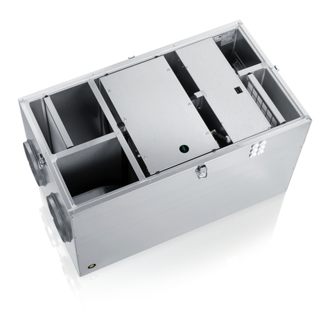
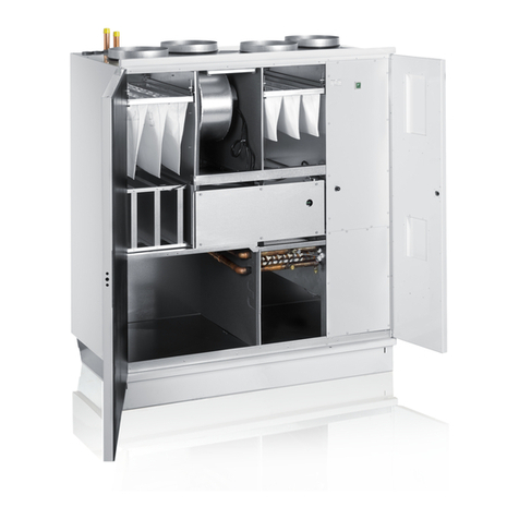
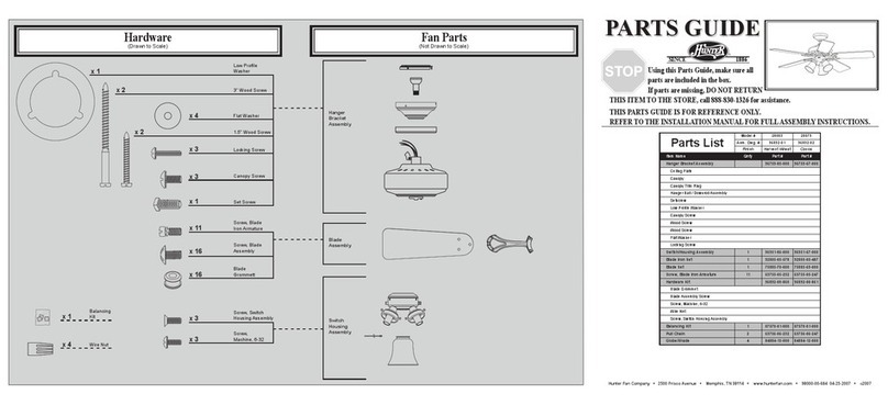
enervent LTR-3 Series Technical manual


This manual suits for next models
6
Table of contents
Other enervent Fan manuals
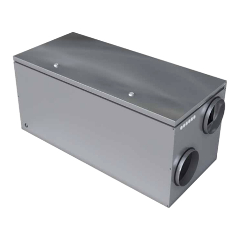
enervent
enervent LTR-5 Z eWind User manual
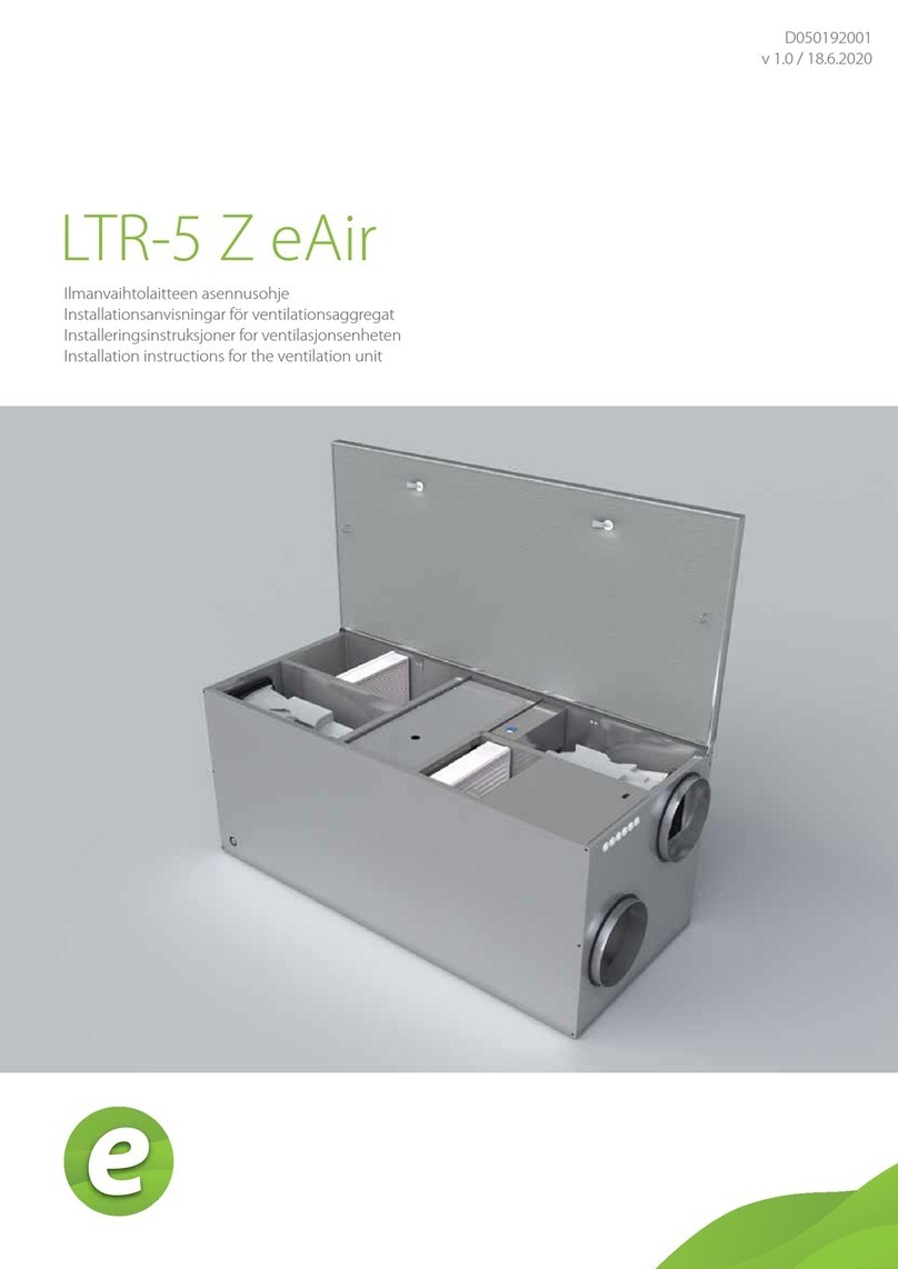
enervent
enervent LTR-5 Z eAir User manual
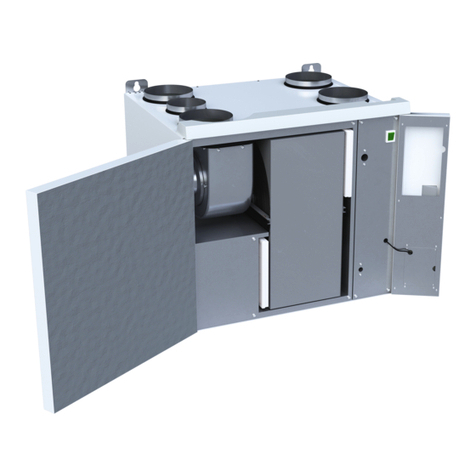
enervent
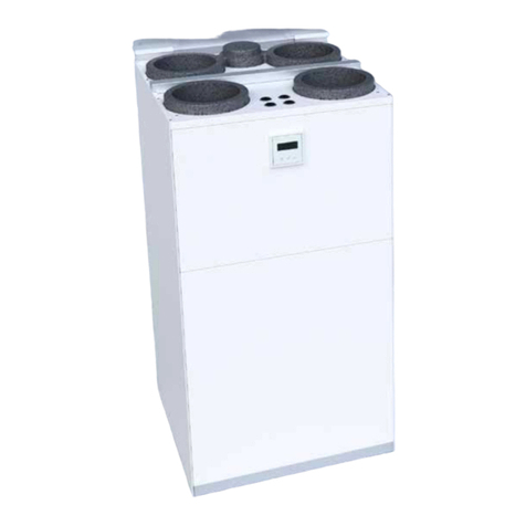
enervent Salla eAir User manual
enervent
enervent Neo eWind User manual
enervent
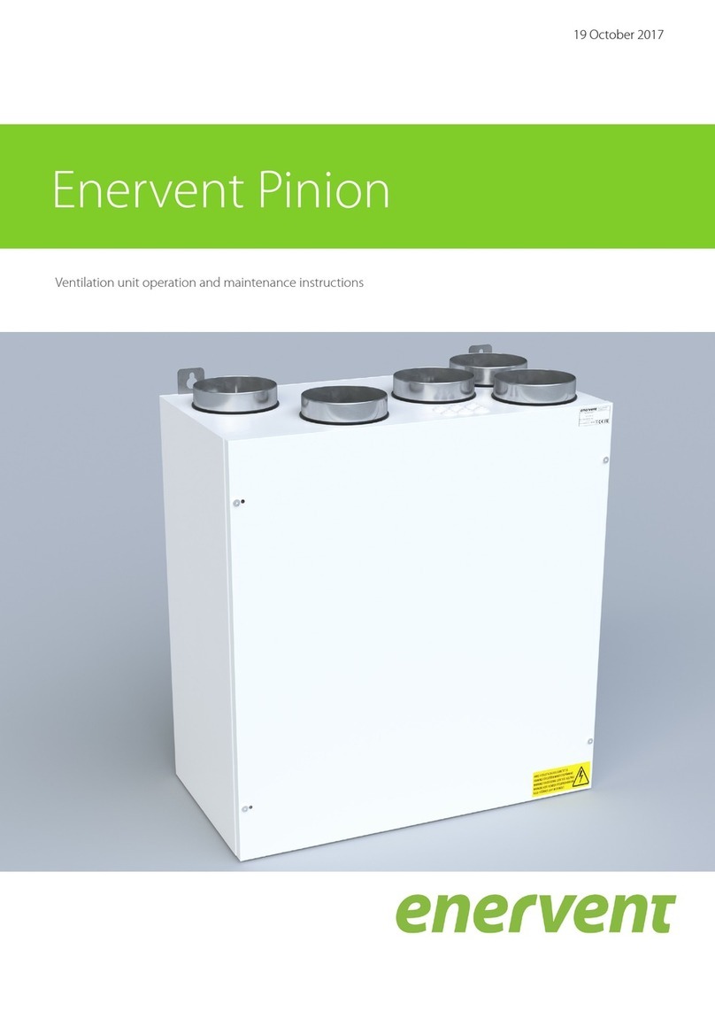
enervent Pinion Troubleshooting guide

enervent
enervent eWind Pinion User manual
enervent
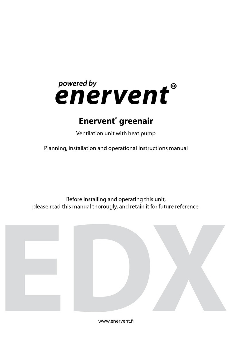
enervent EDX Quick start guide
enervent
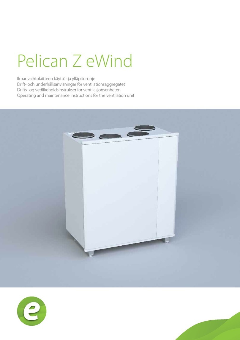
enervent Pelican Z eWind Manual
enervent
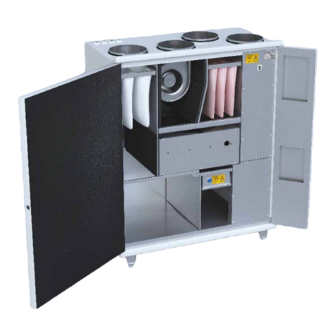
enervent eWind Pelican User manual
enervent
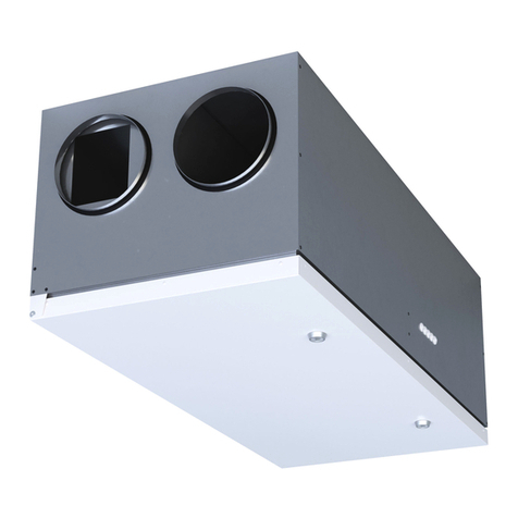
enervent Alta eWind User manual

enervent
enervent LTR-5 Z eWind Manual
enervent
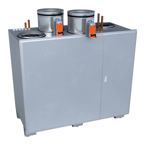
enervent Pallas HP eAir Series User manual
enervent
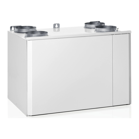
enervent Pingvin XL eAir User manual
enervent
enervent Pingvin XL eWind User manual
enervent
enervent eWind Pinion Manual
enervent
enervent Pegasos Z eWind User manual
enervent
enervent Pelican eAir User manual

enervent
enervent greenair Plaza eco EC Quick start guide

enervent
enervent eWind Pelican Manual

enervent
enervent Salla eWind User manual
Popular Fan manuals by other brands
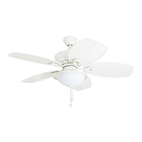
Harbor Breeze
Harbor Breeze 40045 manual
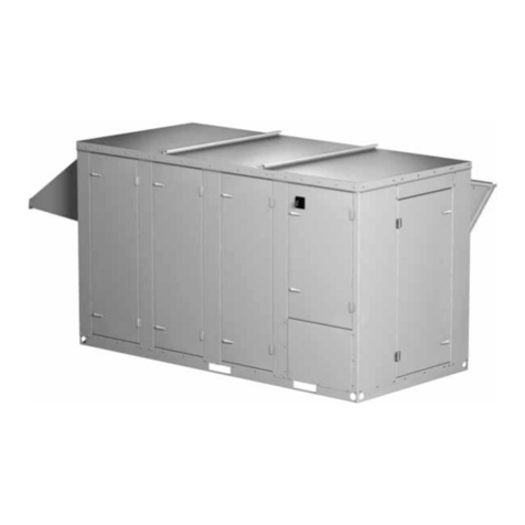
Greenheck
Greenheck PVE-20 Installation, operation and maintenance manual
Haier
Haier FDPH112 user manual

Gaggenau
Gaggenau AL 400 use and care manual

QUORUM INTERNATIONAL
QUORUM INTERNATIONAL The Angel installation instructions

ZIEHL-ABEGG
ZIEHL-ABEGG ECblue Assembly instructions

Ventamatic
Ventamatic MaxxAir HVFF 20 Instruction & owner's manual
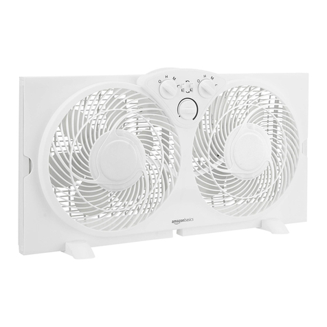
AmazonBasics
AmazonBasics B07YJD9K21 manual

World Power Technologies
World Power Technologies WHISPER H40 datasheet
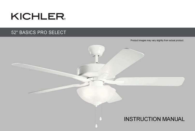
Kichler Lighting
Kichler Lighting BASICS PRO SELECT 330017MWH instruction manual

Faro Barcelona
Faro Barcelona lombok installation guide

Craftmade
Craftmade FRM52 installation guide
