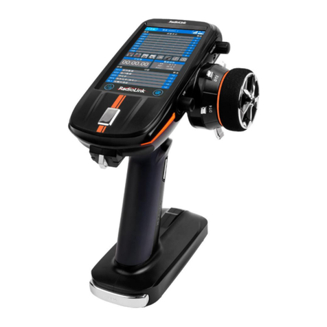
RadioLink AT9S PRO User manual

1
AT9S Pro
(DSSS&FHSS&CRSF)
Instruction Manual
Adaptable to
Helicopter/Fixed-wing/Glider/Multirotor/Car/Boat/Robot
2021.09

2
Contents
PART 1. INTRODUCTION OF AT9S Pro --------------------------------------------------------- 5
1.1 SAFETY PRECAUTIONS --------------------------------------------------------------- 5
1.2 Basic introduction of AT9S Pro ---------------------------------------------------------6
1.2.1 Technical Parameters ----------------------------------------------------------- 6
1.2.2 Configuration List -------------------------------------------------------------- 7
1.2.3 Recommended Configuration ----------------------------------------------------7
1.2.4 Transmitter ------------------------------------------------------------------- 8
1.2.5 Basic Usage and Settings -------------------------------------------------------- 9
1.2.6 Transmitter Displays ----------------------------------------------------------- 10
1.3 Receiver -------------------------------------------------------------------------- 11
1.3.1 Compatible Receivers ----------------------------------------------------------11
1.3.2 Two signal working modes of R9DS ---------------------------------------------- 12
1.3.3 The connection of the receiver -------------------------------------------------- 13
1.3.4 Binding ----------------------------------------------------------------------16
1.3.5 Installment of antenna --------------------------------------------------------- 16
1.3.6 RSSI testing ------------------------------------------------------------------ 17
1.4 Connection with TBS Crossfire TX ----------------------------------------------------- 17
PART 2. BASIC FUNCTION OF AT9S Pro ------------------------------------------------------- 19
2.1 PARAMETER ----------------------------------------------------------------------- 19
2.2 Model Select ---------------------------------------------------------------------- 20
2.3 Model Type ----------------------------------------------------------------------- 21
2.4 End Point (also called EPA) -----------------------------------------------------------22
2.5 SUB TRIM ------------------------------------------------------------------------- 23
2.6 Servo Reversing (REVERSE) -----------------------------------------------------------24
2.7 Dual rates and exponential (D/R,EXP) -------------------------------------------------- 24
2.8 MOTOR CUT (Throttle Cut) ---------------------------------------------------------- 27
2.9 IDLE DOWN (ACRO only) ------------------------------------------------------------ 29
2.10 TRIM ---------------------------------------------------------------------------- 30
2.11 Fail Safe (F/S) --------------------------------------------------------------------- 31
2.12 Auxiliary Channel (AUX-CH) ---------------------------------------------------------31
2.13 TIMER --------------------------------------------------------------------------- 33
2.14 TRAINER ------------------------------------------------------------------------- 34
2.15 Logic Switch Selection (LOGIC SW) --------------------------------------------------- 35
2.16 SERVO ---------------------------------------------------------------------------36
2.17 TELEMETRY ---------------------------------------------------------------------- 36
2.18 SYSTEM SETTING ------------------------------------------------------------------38
PART 3. AT9S Pro ADVANCE MENU FUNCTIONS ----------------------------------------------- 39
3.1 ACRO ADVANCE FUNCTION MENU --------------------------------------------------- 39
3.1.1 Programmable MIX ----------------------------------------------------------- 39
3.1.2 FLAPERON (ACRO/GLID 1A+1F ) ------------------------------------------------ 43
3.1.3 FLAP-TRIM ------------------------------------------------------------------ 44
3.1.4 AILE DIFF (ACRO/ GLID 2A+1F/ GLID 2A+2F) -------------------------------------- 45
3.1.5 Air Break (ACRO/ GLID) -------------------------------------------------------- 46
3.1.6 ELEV-FLAP mixing (ACRO/GLID) -------------------------------------------------48
3.1.7 Dual Elevator Servos (with a rudder) (AILEVATOR) (ACRO) --------------------------- 48
3.1.8 Snap Rolls (ACRO) ------------------------------------------------------------ 49
3.1.9 V-Tail (ACRO/ GLID) -----------------------------------------------------------51
3.1.10 ELEVON -------------------------------------------------------------------- 51

3
3.1.11 Gyro Sense ----------------------------------------------------------------- 52
3.1.12 THR CURVE (ACRO) ---------------------------------------------------------- 53
3.1.13 THR-DELAY (ACRO) ---------------------------------------------------------- 54
3.1.14 THROTTLE-NEEDLE mixing (ACRO/ HELI): --------------------------------------- 54
3.1.15 ATTITUDE ------------------------------------------------------------------ 56
3.1.16 SERVO-DLY -----------------------------------------------------------------56
3.2 GLID ADVANCE MENU -------------------------------------------------------------- 56
3.2.1 Programmable MIX ----------------------------------------------------------- 58
3.2.2 FLAPERON -------------------------------------------------------------------58
3.2.3 V-TAIL ---------------------------------------------------------------------- 58
3.2.4 OFFSET ----------------------------------------------------------------------58
3.2.5 CAMBER-FLP -----------------------------------------------------------------59
3.2.6 Camber Mixing --------------------------------------------------------------- 60
3.2.7 AILE/ RUDD MIX -------------------------------------------------------------- 60
3.2.8 ELEV-FLAP mixing ------------------------------------------------------------ 61
3.2.9 SPOILER MIX (GLID) ----------------------------------------------------------- 61
3.2.10 FLAP-TRIM ----------------------------------------------------------------- 62
3.2.11 CONDITION ---------------------------------------------------------------- 62
3.2.12 SERVO-DLY -----------------------------------------------------------------62
3.2.13 BUTTERFLY (crow) mixing ----------------------------------------------------- 62
3.2.14 B.FLY-ELEV ----------------------------------------------------------------- 63
3.2.15 ELEVON -------------------------------------------------------------------- 64
3.2.16 START DELAY (GLID 1A+1F only) ----------------------------------------------- 64
3.2.17 AILE-DIFF(2A+1F、2A+2F) ------------------------------------------------- 64
3.2.18 AILE-FLAP(GLID 2A+2F only)(2A+2F) -----------------------------------------64
3.3 HELICOPTER ADVANCE MENU FUNCTIONS -------------------------------------------- 65
3.3.1 Programmable MIX ----------------------------------------------------------- 66
3.3.2 THR-CURVE and PIT-CURVE ----------------------------------------------------66
3.3.3 GYRO SENSE ----------------------------------------------------------------- 67
3.3.4 REVO MIX ------------------------------------------------------------------- 67
3.3.5 THROTTLE HOLD ------------------------------------------------------------- 69
3.3.6 HOVERING ADJUSTMENTS (HOV-THR and HOV-PIT): ------------------------------ 70
3.3.7 HIGH/LOW PITCH (HI/LO-PIT) -------------------------------------------------- 71
3.3.8 OFFSET ----------------------------------------------------------------------72
3.3.9 DELAY ---------------------------------------------------------------------- 73
3.3.10 GOVERNORS ----------------------------------------------------------------73
3.3.11 Throttle Mixing (THROTTLE MIX) ----------------------------------------------- 75
3.3.12 SWASH-RING --------------------------------------------------------------- 75
3.3.13 THROTTLE NEEDLE -----------------------------------------------------------76
3.3.14 CONDITION ---------------------------------------------------------------- 76
3.3.15 SERVO-DLY -----------------------------------------------------------------77
3.4 MULTIROTOR &CAR & BOAT ADVANCE MENU FUNCTIONS ------------------------------ 77
3.4.1Programmable MIX ------------------------------------------------------------ 77
3.4.2 Throttle Curve ---------------------------------------------------------------- 77
3.4.3 SERVO-DLY ------------------------------------------------------------------77
3.4.4 Attitude (Multirotor) ----------------------------------------------------------- 77
3.4.5 Throttle Hold (Multirotor) ------------------------------------------------------ 77
3.4.6 GYRO-SENSE (Car & Boat) ----------------------------------------------------- 78
3.4.7 SPEED (Car & Boat) ----------------------------------------------------------- 78
3.4.8 A.B.S ------------------------------------------------------------------------ 79
PART 4. TUTORIAL -------------------------------------------------------------------------80

4
4.1 Use tutorial ------------------------------------------------------------------------80
4.1.1 How to Upgrade Radiolink AT9S PRO firmware ------------------------------------ 80
4.1.2 How to connect RadioLink AT9S Pro with Blacksheep TBS Crossfire TX ---------------- 80
4.1.3 How to change RadioLink AT9S Pro AT9S/AT10II Joystick Modes --------------------- 80
4.1.4 Radiolink AT9S/AT9S Pro/AT9 Remote Controller Data Copy Function -----------------80
4.1.5 Airplane's voltage Telemetry on AT9S Pro Screen without Flight Controller ------------- 80
4.1.6 How to use RadioLink wireless trainer cable on RadioLink AT9S Pro ------------------- 80
4.1.7 How to setup parameters when use Radiolink AT9S Pro ----------------------------- 80
4.1.8 How to| Make RadioLink receiver R9DS bind with AT9S Pro -------------------------- 80
4.1.9 How to Distinguish Between Mode 1 and Mode 2 of Radiolink AT9S Pro ---------------80
PART 5. AFTER-SALES SERVICE POLICIES ------------------------------------------------------81
Thanks -----------------------------------------------------------------------------------82

5
PART 1. INTRODUCTION OF AT9S Pro
1.1 SAFETY PRECAUTIONS
1.Do not use the remote controller in the rain! Avoid moisture entering the transmitter. If it is
unavoidable to use this product in humid weather (such as competitions), please cover your remote controller
and receiver with a waterproof cloth, and do not fly if there is lightning.
2.Don’t use it in rainy and snowy weather. This weather environment will interfere with the remote
controller equipment, resulting in loss of control and accidents!
3.Don’t use this equipment in crowded areas and places prohibited by national laws and regulations!
4.Do not allow children (Less than 14 years old) to touch this product. This product is not a toy. Please
be careful when operating in scenes where children are present.
5.Please strictly abide by local laws and regulations when flying to ensure safe flight!
6.Make sure the throttle stick and trim button are set at the lowest end before turning on, then turn on
the power button and check whether the power supply is sufficient, then turn on the receiver!
7.Check whether the various actions of servo are consistent with the direction of the corresponding
joystick before operating the model. If they are inconsistent, please adjust before using!
8.Please turn off the receiver and controlled equipment before stopping use, and then turn off the power
supply of the transmitter. If the operation is reversed, it may cause loss of control and cause an accident!
9.The operating voltage of transmitter is 7.4V~18V. Please do not use battery outside this voltage
range when replacing the battery by yourself.
10.You can choose 8 dry battery or 2S~4S lithium battery to power the transmitter. Please learn about
the characteristics of lithium battery and use the professional lithium battery charger. Improper operation may
cause permanent damage and risk of fire.
11.There is a Micro USB port at the bottom of AT9S Pro. Please note the port is for upgrading firmware,
not for charging.

6
1.2 Basic introduction of AT9S Pro
1.2.1 Technical Parameters

7
1.2.2 Configuration List
1.2.3 Recommended Configuration
The below accessories sold separately. You can enter the Aliexpress Official Store to purchase. Or login
to the Radiolink official website for product details.
AT9S Pro transmitter×1 R9DS Receiver×1 Lanyard×1
Packing box×1 Instruction Manual×1 THR return accessories×1
PRM-01 Voltage Telemetry module TBS crossfire cable
PRM-03 Telemetry module Wireless trainer cable

8
1.2.4 Transmitter
1
2
3
4
5
1.Earth Pole
2.Null
3.Voltage Output: 7.4-18V
4.Output: PPM/SBUS/CRSF
5.Input: RSSI

9
1.2.5 Basic Usage and Settings
Buttons and switches
MODE Button : Long press MODE button to enter BASIC MENU or ADVANCE MENU, short press
the MODE button to switch the MENU.
END Button : Once press to enter SERVO display starting from start-up screen or exit from the
any parameter setup menu, Twice press to enter RECEIVE display staring from start-up screen.
PUSH Button : Rotate the PUSH button to move the cursor or modify the parameter value of the
function, Short press or Long press the PUSH key to confirm.
Usage example:Reduce the EPA(End Point Adjustments) of “4: RUDD”.
1. Long press the to enter the "BASIC MENU", rotate the to move the cursor to "END
POINT", short press the to confirm and enter the EPA setting interface.
2. In "END POINT", rotate the to move the arrow to "4: RUDD", short press the to select, push
the Rudder Stick to the left, move the cursor to the left percentage,and rotate the to modify the
percentage (the larger the percentage, the larger the EPA of the servo), press the to confirm, and press
the to return.
Note:For normal functions, short press the to confirm, but when modifying the "MODEL SEL" and
"MODE TYPE", long press the for 1 second to confirm.
Throttle/Rudder/Aileron/Elevator Stick controls 1 to 4 channels by default.
Two VR knob switches and two VR slider switches on the back meet the needs of pan/tilt control,
and the functions of these switches can be customized.
Toggle switch, AT9S Pro has 4 two-stage switches, 3 three-stage switches and a reset switch. All
switches can be customized function setting. For details, please refer to www.radiolink.com.
SWITCH ASSIGNMENT TABLE
• The factory default functions activated by the switches and knobs for a AT9S Pro transmitter are
shown below.
• Most AT9S Pro functions may be reassigned to non-default positions quickly and easily.
Always check that you have the desired switch assignment for each function during set up.
Switch/Knob
A or H
Airplane (ACRO)
Sailplane/Glider
(GLID)
Helicopter (HELI)
MULTIROTOR
SWITCH A
elevator dual rate
ch10
elevator dual rate
down=butterfly on
ch10
elevator dual rate
ch10
elevator dual rate
ch10

10
SWITCH B
rudder dual rate
ch9
rudder dual rate
ch9
rudder dual rate
ch9
rudder dual rate
ch9
SWITCH C
up = ELE-FLP on
center/down=
IDLE-DOW N
down = AIRBRAKE on
up = ELE-FLP on
center = Distance
cond.
down = Landing cond.
governor
attitude
SWITCH D
aileron dual rate
aileron dual rate
aileron dual rate
aileron dual rate
SWITCH E or G*
Landing gear/ch5
——
Throttle hold/ch5
——
SWITCH F or H*
Snap roll /trainer
Trainer
Trainer/throttle
cut
trainer
SWITCH G or E*
——
up = Speed cond.
idle-up 1 and 2
——
SWITCH H or F*
——
down = Start cond.
idle-up 3 /gyro
——
KNOB A
Flap/ch6
(
flap trim if
FLAPERON on)
Flap/ch6
HOVERING
PITCH
ch 6
KNOB B
ch 8
ch 8
ch 8
ch 8
KNOB C
Spoiler/ch7
(disabled if AIL-DIFF
on)
ch 7
(disabled if AIL-DIF
on)
HOVERING
THROTTLE
ch7
ch 7
SLIDER D
——
ch 5
——
——
1.2.6 Transmitter Displays
Transmitter Displays & Buttons
When you first turn on your transmitter, a confirmation double beep sounds, and the screen shown below
1. The model name and the user name. Before flying, or even starting the engine, be sure that the model type
and name appearing on the display matches the model that you are about to fly! If you are in the wrong model
memory, servos may be reversed, and travels and trims will be wrong, leading to an immediate crash.
2. The signal tower. When it is connected to the receiver successfully, there will be a signal It shows the
signal strength between the transmitter and the receiver. After connection with TBS crossfire transmitter, there
will be a signal of CRSF.
3. The voltage of the transmitter and the flight
attitude.
4. The boot time of the transmitter.
5. T1/2 for Timer 1/2. You can set a timer for flight
time to avoid crash caused by over discharging and
low voltage of the battery. You can also set it to
control limited time function for Flight fixed
maneuvers.
6. The boot time of the model. You can also set
other timer function in the menu.

11
7. After successful connection between the transmitter and the receiver, RX will shows the voltage of the
receiver.(When using receiver R6DS, R6DSM and R12DSM, RX will not be displayed )
8. After connecting with telemetry module such as PRM-01 or PRM-01, EXT will shows the model voltage.
You can buy it on RadioLink official website.
9. Take model 2 left hand as an example. There are 4 calibrated scale on the screen edges, which represents
the trimming of aileron, elevator, throttle and rudder, corresponding to four trimmer button on the transmitter.
Do not use trimmer button before first flight. It is suitable to trim flight attitude during first horizon flight.
ALARMING
When the transmitter is powered on, warning or error may happen by the following probability
1. Battery low voltage alarming
Lithium battery 2S-4S can fit for the transmitter, warning voltage can be
self-set according to different battery.
Setting step: power on the transmitter, press and hold MODE one
second to enter basic menu, and press PUSH to enter PARAMETER.
Choose TX ALARM by DIAL and PUSH to change relative data.
Suggested min voltage is not less than 7.4V.
When the transmitter voltage is less than the setting voltage, it will beep
till the transmitter is powered off. Most important thing is to land your
model plane when the transmitter alarms.
2. Mixing alarm
When the transmitter alarms mixing, it means at least one mixed switch is active. And when it is inactive,
warning will stop then. When the transmitter is powered on, in different model type, mixing switch is shown as
below:
ACRO: throttle cut, idle down, snap roll, air brake
GLID: butterfly, condition
HELI: throttle cut, throttle lock, speed up
If the warning continues even the related switch is set OFF, probably it is because some programs mixed by
one switch and status OFF reversed. Now you need to set mixing
alarm again by DIAL.
3. Throttle down alarm
When the transmitter alarms THR POSITION, rotate PUSH to stop the
alarm. It is mainly for reminding the user to keep the throttle at the
lowest position to operate safely. If the user want to turn off the alarm,
go to basic menu- SYSTEM. Set TH-DOWN to OFF.
1.3 Receiver
1.3.1 Compatible Receivers
AT9S Pro is a 10 channels transmitter, support 2.4G DSSS and FHSS dual hybrid spread spectrum, 16
channels pseudo random frequency hopping.
AT9S Pro sells with receiver R9DS.
R9DS is a 9 channels receiver when working with PWM signal(red LED), it will a 10 channels receiver when
working with S-BUS signal(purple/blue LED).
Besides R9DS, AT9S Pro is also compatible with Radiolink R6DS, R10DS, R12DS and super mini 10
******WARNING!!!******
TX LOW POWER!
******WARNING!!!******
THR POSITION!

12
channels receiver R6DSM and 12 channels mini dual antenna receiver R12DSM.
R6DS, is a 6 channels receiver when working with PWM signal while it is a 10 channels receiver when
working with SBUS or PPM signal.
R12DS, is a 11 channels receiver when working with PWM signal while it is a 12 channels receiver when
working with SBUS signal.
Note AT9S Pro is default 10 channels, you can upgrade it to 12 channels with USB cable. You have to setup
AT9S Pro to 12 channels first if you use 12 channels receivers R12DS or R12DSM while you have to setup
AT9S Pro back to 10 channels when you use 10 channels receiver R6DS, R6DSM and R10DS.
To setup to 12 channels: power on your AT9S Pro--Press Mode button one second into BASIC MENU--into
SYSTEM menu--change CH-SELECT from 10CH to 12CH.
Since RadioLink radio control systems are not open source, RadioLink transmitters are just compatible with
RadioLink receivers and vice versa.
When AT9S Pro is connected with TBS Crossfire TX, it only supports crossfire receiver.
1.3.2 Two signal working modes of R9DS
There are two signal working modes, PWM and SBUS&PWM signal output. Short press ID SET twice within
1s, the working mode will change.The RED led indicates the PWM output and BLUE/PURPLE led indicates
SBUS signal.
(1) PWM signal output working mode:RED led indicates PWM signal output, 9 channels totally
(2) SBUS&PWM dual signal output working mode: blue/purple LED indicates SBUS&PWM signal output at
the same time with 10 channels totally. CH9 outputs SBUS signal while the original CH1 outputs CH3 PWM
CH5 (AUX)
CH6 (AUX)
CH7 (AUX)
CH8 (AUX)
CH1 (AILE)
CH2 (ELEV)
CH3 (THRO)
CH4 (RUDD)
Antenna
Telemetry Connection
Port
LED
Indicator
ID

13
signal and original CH2 to CH6 output CH6 to CH10 PWM signal at the same time.
1.3.3 The connection of the receiver
Dupont thread is used to connect the receiver. The common color is white/red/black or yellow/red/brown.
The signal wire is light color, while the ground wire is dark color. The three wires are corresponding
to . When connecting with the servo wires, the signal wire is upward and the ground wire is
downward.
Note: All RadioLink receivers are designed with Anti-polarity connect protection. When the connection of
the servo wires are reversed, the receiver will stop working and it won’t be damaged. But when connecting
the servo at this time, the servo may be damaged.
The below chart is to introduce the default output channel of the receiver when setting different models.
Take acrobatic as an example.
RX
output
& CH
Glider
ACROBASI
C
Helicopter
Car/Boat
GLID(1A+1 F)
GLID
(2A+1F)
GLID
(2A+2F)
ELEV
ON
FLAPERO
N
AILE-DIFF
AILE-DIF
F
1
Combi
ned
elev-2
&ailero
n1
elev-1
&ailero
n-2
Combined
flap-2
&aileron-1
aileron-1
Aileron-1
ailerons/aile
ron-1¹/com
bined
flap-2&ailer
on-1¹
aileron/cycli
c roll
Spare/rudde
r
2
Combi
ned
elev-1
&ailero
n-2
Elevator/co
mbined
rudder-2&e
lev-1¹
Elevator/c
ombined
rudder-2&
elev-1¹
Elevator/
combined
rudder-2
&elev-1¹
e
levator
Elevator/cycl
ic pitch
Spare/throttl
e

14
3
spare/
motor
spare /
motor
spare /
motor
spare/mo
tor/splr-2¹
throttle
Throttle
throttle/Spar
e
4
Rudder
Rudder/co
mbined
rudder-2&e
lev-2²
Rudder/co
mbined
rudder-2&
elev-2²
rudder/co
mbined
rudder-1
&elev-2²
rudder
Rudder
Rudder/spar
e
5
spare/s
plr-2¹
spare/spoil
er-2¹
spare/spoil
er-2¹
flap-2
spare/landi
ng
gear/aileron
-2¹
³/combined
flap-1 and
aileron-2² ³
Spare/gyro
Gyro/spare
6
Flaps
Combined
flap-1&ailer
on-2
flaps
flap-1
spare/flaps/
combined
flap-1 and
aileron-2²
Pitch(collecti
ve pitch)
Spare
7
Spare
spare
ailron-2
Aileron-2
spare/ailero
n-2¹
Spare/gover
nor
spare
8
spare/s
plr/splr
-1¹
spare/splrs
/splr-1¹
spare/splrs
/splr-1¹
spare/splr
s/splr-1¹
spare/eleva
tor-24/mixtu
re control
spare/mixtur
e control
Spare
9
Spare
spare
spare
spare
spare
Spare
spare
10
Spare
spare
spare
Spare
spare
spare
spare
11
Spare
spare
spare
spare
spare
Spare
spare
12
Spare
spare
spare
Spare
spare
spare
spare
The connection between the receiver and the model voltage telemetry module
How to connect PRM-01with the receiver

15
PRM-01 shows real-time model Voltage. When the voltage is low, the transmitter will vibrate with beep sound.
And there is text prompt on the screen. The flight will be safer.
PRM-03 Real-time OSD information telemetry module
Real-time model data allows users to receive crucial information on the model's systems. With flight module
PRM-03 and flight controller PIXHAWK/Mini Pix/TURBO PiX, model voltage, speed, climb, throttle, longitude,
latitude, altitude, GPS, RSSI, flight mode, yaw, roll, pitch, and distance are display on the transmitter screen.
Telemetry modules are sold separately. You can enter the Aliexpress Official Store to purchase. Or login to
the RadioLink official website for product details.

16
1.3.4 Binding
Each transmitter has an individually assigned, unique ID code. Receiver should bind to transmitter before
starting operation. Once binding is complete, the ID code will be stored in the receiver and no further binding
is necessary unless the receiver is used with another transmitter. When you purchase a new R9DS, this
procedure is necessary; otherwise the receiver will not work.
1. Put the transmitter and the receiver close to each other about 50 centimeters.(much too close distance
may cause signal jamming)
2. Power on AT9S Pro and receiver R9DS.
3. Turn on AT9S Pro and it will automatically bind with the closest receiver. Turn on AT9S Pro. Long press
ID SET,which is on the side of receiver for more than 1 second and release until the RED/PURPLE LED
flashes. When the LED stops flashing and is always on , binding is complete.
4. at the top of the screen means it hasn’t finished binding or the failure of binding. Bind again until you
see . at the top of the screen.
Please note: Since RadioLink radio control systems are not open source, RadioLink transmitters are ONLY
compatible with RadioLink receivers. When the transmitter connect with TBS Crossfire TX, it supports
crossfire receiver.
1.3.5 Installment of antenna
Installment of antenna
Receiver Antenna Installment
①Keep antennas as straight as possible, or the effective control range will reduce.
②Big models may contain metal parts that influence signal emission. In this case, antennas should be
positioned at both sides of the model to ensure the best signal status in all circumstances.
③Antennas should be kept away from metal conductor and carbon fiber at least half inch away and no
over bending.
④Keep antennas away from motor, ESC or other possible interference sources.
⑤Press and hold the ID SET for more than one second and receivers will start to work with the RED
LED on.
Note Receiver contains some electronic components of high-precision. Be careful to avoid strong vibration
and high temperature.
When all the above steps are complete, please turn off the transmitter and repower on to test if the receiver is
correctly connected with it.
1. Transmitter Antenna Installment
①The transmitter antenna is adjustable so please make sure that the antenna never points directly
at the model when flying as this may possibly decrease the receiver signal.
②Keep the antenna perpendicular to the transmitter to optimize the receiver performance. It also
depends on how you hold the transmitter. But in most cases, adjusting the antenna with perpendicular
position to the transmitter surface will achieve the best result. Please adjust the transmitter antenna
according to the way you hold the transmitter.
③Never grip the antenna when flying as this degrades= effective control range.

17
1.3.6 RSSI testing
Before flight, always remember to do the RSSI testing to avoid the possible unexpected signal loss. Power
on transmitter and receiver, keep them with the distance of about 30 centimeters and both antennas
straight.
Enter the parameter setup menu by press MODE one second, you can check the RSSI in RECEIVE.
The RSSI is 0 to 30dBm is normal when the transmitter is apart about 30 centimeters from the receiver, the
signal is more better the RSSI data is more close to 0.
1.4 Connection with TBS Crossfire TX
① Power on the transmitter- Long press the Mode key to enter the BASIC MENU->Rotate the Scroll
Dial to highlight the SYSTEM option and depress the Enter key->Select the OUT and change the output as
CRSF

18
Note : The setting is to define the signal output of the simulator port at the back of AT9S Pro. If the
simulator or trainer cord to connect, there are other output options as SBUS and PPM.
② Connect TBS crossfire transmitter with the CRSF cable to the simulator port at the back of AT9S
Pro.
③ After the binding of TBS Crossfire TX and receiver, check if there is“CRSF”next to the signal tower at
the screen, which means TBS Crossfire TX can work properly.
The detailed steps please refer to the video tutorial https://youtu.be/g_mfHdeEQCo
Note: The compatibility function with TBS Crossfire TX is only available in AT9S Pro, which CANNOT be
upgraded from AT9S directly.

19
PART 2. BASIC FUNCTION OF AT9S Pro
The BASIC menu is suitable for all type models, including airplane, helicopter, glider, MULTIROTOR,
cars and boats. Please go to PART 3 for advance menu.
2.1 PARAMETER
In PARAMETER, you can set LANGUAGE, STK-MODE, RF-MODE, BACKLIGHT, USER NAME, TX-ALARM,
RX-ALARM, EXT-ALARM, LockScreen and sound. You can also check the firmware version. If you need to
download the latest firmware, please click the link here: www.radiolink.com/at9spro_firmwares
Display language: can be selected the display language of the function name, etc. in each function menu. The
screen reads "LANGUAGE". Change this to the desired language. Go to BASIC MENU- PARAMETER-
LANGUAGE to select.
RF Mode: includes on and off. The LED indicator will become solid green when RF Mode is active. Set RF
mode to OFF to save energy when using the simulator. Set RF mode to on when operating the model.
BLACKLIGHT: change number to adjust the intensity of the backlight. 20 indicates the brightest scrren. 0
indicates the darkest screen.
USER NAME: user name can be set by DIAL and PUSH with letters and numbers.
Alarming voltage
TX-ALARM: The minimum voltage alarm of transmitter. It can be self-set. When it is below the minimum
voltage, the transmitter will vibrate and sound the alarm. The recommended voltage is 7.4V for 2S
lithium battery, 11.1V for 3S lithium battery, 14.8V for 4S lithium battery.preset 8.6V.
RX-ALARM: The minimum voltage alarm of receiver. It can be self-set. When it is below the minimum voltage,
the transmitter will vibrate and sound the alarm.
EXT-ALARM: The minimum voltage alarm of Telemetry module. It can be self-set. When it is below the
minimum voltage, the transmitter will vibrate and sound the alarm.
Note: the RX-ALARM is only available when the transmitter connects to PRM-01 or PRM-03 Telemetry
module. Telemetry module sold separately. You can enter the Aliexpress Official Store to purchase. Or login to
the Radiolink official website for product details.
Stick Mode: The screen reads "STK-MODE". Change this to the correct mode. Note that this will NOT change
the throttle and elevator ratchets, etc. Those are mechanical changes that must be done by a service center.
There are 5 stick models.
Stick mode of the transmitter
mode
Aileron
Elevator
Throttle
Rudder
Mode 1
Right
hand,
left and
right
Left
hand, up
and
down
Right
hand,
up and
down
Left
hand,
left and
right
Mode 2
Right
hand,
left and
right
Right
hand, up
and
down
Left
hand,
up and
down
Left
hand,
left and
right

20
Mode 3
Left
hand,
left and
right
Left
hand, up
and
down
Right
hand,
up and
down
Right
hand,
left and
right
Mode 4
Left
hand,
left and
right
Right
hand, up
and
down
Left
hand,
up and
down
Right
hand,
left and
right
-custo
mized
The default action is the same with
Mode 1. Please note that the stick of
channel 1 to 4 cannot be changed in
model 1 to 4. But in the customized
model, you can change the control
switch of STK1/2/3/4 to other switch
such as SWA/VRA. If you want to
change it, make sure to disconnect
power supply to avoid safety accident.
LockScreen: It can be set to OFF or “1s-254s”, When it is set to “1s-254s”, the screen will be locked if there is
no operation in this time period. The setting is to avoid wrong operation during flight. Long press push button
for 1 second to unlock the screen.
Sound: When it is on, there is sound when setting the function or alarming. When it is off, there is no sound.
2.2 Model Select
Model submenu: includes three function that manage model
memory: MODEL SELECT,MODELCOPY and MODEL NAME.
Since these functions are related, and all basic features are used
with most models, they are together in the Model submenu.
Totally there are 15 models stored in the system, followed by model
name and plane type to use on tap, thus you don’t need to set
every time for different plane. MODEL NAME, MODEL TYPE and
transmitter voltage. Make sure that MODEL TYPE is accomplished
with your plane type before flight. Or it will cause error in servo and rudder.
Select
Press Push button to choose the model you want. Long press push button to confirm and press End
button to come back to the menu.
Caution: Do not switch the model when the model is powered on. Disconnect power supply of the model when
switching model. After selecting model, enter the basic menu-Reverse. Set the throttle to reverse.
COPY
Save the present data as another model type, it will be displayed by shadow area to differ from. When this
copy start, the object data will be fully covered including name, type and module type, and cannot recover.
Caution: when you save the present model type as another, all related data will be copied including the
original model name. Accordingly, if you want to change the model type, the whole data need to reset, also for
model name. The first thing to copy is to change the model type or delete the original name and rename a
new model to avoid confusion.
Model Name
This is used to set the present model name. Name all model to identify each other, and fast select the
Other manuals for AT9S PRO
3
Table of contents
Other RadioLink Control System manuals
Popular Control System manuals by other brands

ccei
ccei tild VP operating instructions

Pentair
Pentair INTELLICENTER installation guide

CAME
CAME G2080I installation manual

tbs electronics
tbs electronics H64 Installation instructions & user manual

McCue
McCue BOL-WALKWAY installation instructions

Allen-Bradley
Allen-Bradley SoftLogix5800 System user manual