EnOcean EasyFit EMCSA User manual

USER MANUAL
EMCSA / EMCSU / EMCSJ
ENOCEAN MAGNET CONTACT SENSOR
© 2022 EnOcean | www.enocean.com F-710-017, V1.0 EMCSx User Manual | April 2022 | Page 1/31
Patent protected:
WO98/36395, DE 100 25 561, DE 101 50 128,
WO 2004/051591, DE 103 01 678 A1, DE 10309334,
WO 04/109236, WO 05/096482, WO 02/095707,
US 6,747,573, US 7,019,241
Observe precautions! Electrostatic sensitive devices!
EMCSA / EMSCU / EMCSJ
EnOcean Magnet Contact Sensor
(Stepcode DE and later)

USER MANUAL
EMCSA / EMCSU / EMCSJ
ENOCEAN MAGNET CONTACT SENSOR
© 2022 EnOcean | www.enocean.com F-710-017, V1.0 EMCSx User Manual | April 2022 | Page 2/31
REVISION HISTORY
The following major modifications and improvements have been made to this document:
Version
Author
Reviewer
Date
Major Changes
1.0
AA
MK
22.01.2018
First release
1.1
AA
AA
26.02.2018
Light requirement details added, housing di-
mensions corrected, some more minor addi-
tions
1.2
AA
AA
29.05.2018
Chapter 4.4 added (Installing Supplemental
Battery)
2.0
AA
AA
04.01.2019
Additional supplied Wall Mounting Plate added
(in chapters 2.1, 2.5, 2.6)
2.1
AA
AA
01.02.2019
Tray packaging added (chapter 2.4, new chap-
ter 2.7)
2.2
AA
AA
27.02.2019
EEP number corrected in Chapter 2.2
3.0
AA
MK
12.09.2019
New Step Code DE:
Update with long-term energy storage replacement,
additional transport mode for longer shelf storage &
air cargo, optimized secure mode. Adding infor-
mation about QR Code, new grey housing variant
and new US Version. Update of Regulatory Notes
inclusive European waste treatment.
3.1
AA
MHö
13.01.2020
EMCSJ version added (928 MHz)
3.2
AA
AA
25.02.2020
Battery lifetime calculation added (3.6.4)
3.3
MK
11.04.2022
UK market approval and UKCA added
Published by EnOcean GmbH, Kolpingring 18a, 82041 Oberhaching, Germany
© EnOcean GmbH, All Rights Reserved
Other trademarks and trade names are those of their respective owners.
Important!
This information describes the type of component and shall not be considered as assured
characteristics. No responsibility is assumed for possible omissions or inaccuracies. Circuitry
and specifications are subject to change without notice. For the latest product specifications,
refer to the EnOcean website: http://www.enocean.com.
As far as patents or other rights of third parties are concerned, liability is only assumed for
modules, not for the described applications, processes and circuits. EnOcean does not assume
responsibility for use of modules described and limits its liability to the replacement of mod-
ules determined to be defective due to workmanship. Devices or systems containing RF com-
ponents must meet the essential requirements of the local legal authorities. The modules
must not be used in any relation with equipment that supports, directly or indirectly, human
health or life or with applications that can result in danger for people, animals or real value.
Components of the modules are considered and should be disposed of as hazardous waste.
Local government regulations are to be observed. Packing: Please use the recycling operators
known to you.

USER MANUAL
EMCSA / EMCSU / EMCSJ
ENOCEAN MAGNET CONTACT SENSOR
© 2022 EnOcean | www.enocean.com F-710-017, V1.0 EMCSx User Manual | April 2022 | Page 3/31
TABLE OF CONTENT
1RELATED DOCUMENTS ...................................................................................4
1.1 Installation Instructions .................................................................................4
1.2 Range Planning .............................................................................................4
1.3 Radio Telegram Description ............................................................................4
1.4 Declaration of Conformity...............................................................................4
2GENERAL INFORMATION ................................................................................5
2.1 Basic Functionality.........................................................................................5
2.2 Technical Data ..............................................................................................6
2.3 Environmental Conditions ...............................................................................7
2.4 Ordering Information .....................................................................................7
2.5 Physical Dimensions ......................................................................................8
2.6 Packaging Information –Single Unit Packaging .................................................9
2.7 Packaging Information –Tray Packaging ........................................................ 10
2.8 Device Label ............................................................................................... 11
3FUNCTIONAL DESCRIPTION.......................................................................... 12
3.1 Block Diagram ............................................................................................ 12
3.2 Teach-in to Receiver Unit ............................................................................. 12
3.3 Commissioning and Mode Change.................................................................. 13
3.4 Radio Telegram Format, EEP......................................................................... 14
3.6 Storing the Rolling Code Counter (RLC).......................................................... 16
3.7 Energy Consumption / Battery Lifetime .......................................................... 16
4APPLICATION INFORMATION ........................................................................ 19
4.1 General Installation Instructions.................................................................... 19
4.2 Magnet Positioning ...................................................................................... 19
4.3 Lighting Conditions ...................................................................................... 21
4.4 Installing Supplemental Battery (optional)...................................................... 23
4.5 Transmission Range..................................................................................... 24
5REGULATORY NOTES ................................................................................... 26
5.1 EMCSA Market Approval for European Union (CE) ............................................ 26
5.2 EMCSA Market Approval for United Kingdom (UKCA)........................................ 26
5.3 EMCSU Market Approval for US (FCC) ............................................................ 27
5.4 EMCSU Market Approval for CA (ISED)........................................................... 29
5.5 EMCSJ Market Approval for United Japan (ARIB) ............................................. 31

USER MANUAL
EMCSA / EMCSU / EMCSJ
ENOCEAN MAGNET CONTACT SENSOR
© 2022 EnOcean | www.enocean.com F-710-017, V1.0 EMCSx User Manual | April 2022 | Page 4/31
1RELATED DOCUMENTS
This document describes setup and operation of the EMCSx unit. Related documents are as
follows:
1.1 Installation Instructions
The installation instructions are content of the single unit packaging box
1.2 Range Planning
We recommend following our application notes, in particular AN001 “EnOcean Wireless Sys-
tems - Installation Notes”(PDF) available as download at:
www.enocean.com/en/support/application-notes/
1.3 Radio Telegram Description
EMCSx transmits a radio telegram according to EnOcean Equipment Profile EEP D5-00-01
(contact state) and EEP SIGNAL 0x0E (Entering Transport Mode) as defined in the EnOcean
Equipment Profiles specification:
www.enocean-alliance.org/eep/
If the unit is operated in Secure Mode please refer to the EnOcean security specification:
www.enocean.com/security-specification
1.4 Declaration of Conformity
The Declaration of Conformity for EU and UK can be found at the EnOcean EMCSx product
webpage.

USER MANUAL
EMCSA / EMCSU / EMCSJ
ENOCEAN MAGNET CONTACT SENSOR
© 2022 EnOcean | www.enocean.com F-710-017, V1.0 EMCSx User Manual | April 2022 | Page 5/31
2GENERAL INFORMATION
This user manual specifies EMCSx units with Stepcode DE or later:
▪See chapter “2.8 Product Label and QR Code” to find out the module stepcode.
▪For a detailed description of product change see Product Change Notification (PCN).
▪The user manual for older modules can be downloaded from the product website (V2.2).
2.1 Basic Functionality
EMCSx is an energy-harvesting wireless magnet con-
tact sensor for EnOcean systems.
Powered by a solar cell, EMCSx works absolutely
maintenance-free. An integrated energy store allows
operation for several days in total darkness. In dark
surroundings, a coin cell battery can be retrofitted.
The small housing is easy to be mount on windows,
on doorframes or on cabinets using the included dou-
ble-sided adhesive pad or using the also included
mounting plate. The ultra-slim magnet has a preas-
sembled adhesive pad.
EMCSx supervises an integrated reed contact and re-
ports every status change immediately (open<>closed). In addition, a sign of life signal is
send at regular intervals. In addition to the cyclic wake-up, a wake up is triggered by pushing
the LRN button.
EMCSx provides the option to use enhanced security mode with encrypted communication.
Key product features EMCSx
◼Fully autonomous operation under sufficient lighting with pre-installed solar cell
(Battery backup option for operation in dark surroundings)
◼Very flat magnet with preinstalled adhesive for easy mounting
◼Small housing for easy mounting with double-sided adhesive or mounting plate
-Integrated reed contact
-Integrated energy storage and charging circuit
-Integrated LRN button and TX indicator LED

USER MANUAL
EMCSA / EMCSU / EMCSJ
ENOCEAN MAGNET CONTACT SENSOR
© 2022 EnOcean | www.enocean.com F-710-017, V1.0 EMCSx User Manual | April 2022 | Page 6/31
2.2 Technical Data
On-board power supply
Solar with indoor light, min. 50 lx
Auxiliary power supply
Option for backup battery (CR1225, not in-
cluded)
Antenna
Internal helix antenna
Frequency
EMCSA: 868,300 MHz (ASK)
EMCSU: 902.875 MHz (FSK)
EMCSU: 928.230 MHz (FSK)
Data rate / modulation type
125 kbps
Radiated output power
EMCSA: max +6.4dBm (EIRP)
EMCSU: +99 dBµV/m ± 2 dB
EMCSJ: typ. 0dBm
Sustain condition for battery free opera-
tion
min. 400 lx hours per day
(signs-of-life only, 22°C)
Start-up time with empty energy store
typ. <2.5min @ 400 lx, 22°C 1)
Operation time in darkness
>10 days (energy storage fully charged,
signs-of-life only, 22°C) 2)
Operation time with backup battery
5 years min. (total darkness, 22°C) 3)
Teach-in telegram trigger
Pushbutton behind hole in side wall
Teach-in telegram indicator
LED shining through housing side wall
Sign-of-life transmission
Contact status update once every around
20…30 minutes
EnOcean module integrated
EMCSA: STM 320 for EU/UK with CE/UKCA
EMCSU: STM 320U for US/CA with FCC/ISED
EMCSJ: STM 420J for Japan with ARIB
EnOcean Equipment Profile (EEP)
D5-00-01, SIGNAL 0x0E (Transport Mode)
Note 1: Charging time from empty energy store until a teach-in telegram can be sent.
Note 2: Operation time from a fully charged energy store if telegrams sent on average every 17.5
minutes (signs-of-life). To maintain the performance, please refer to chapter 2.3!
Note 3: For details please see chapter 3.6.4

USER MANUAL
EMCSA / EMCSU / EMCSJ
ENOCEAN MAGNET CONTACT SENSOR
© 2022 EnOcean | www.enocean.com F-710-017, V1.0 EMCSx User Manual | April 2022 | Page 7/31
2.3 Environmental Conditions
Operating and storage temperature Absolute maximum: -20 °C … +60 °C
Recommended 1): +10 °C…+30 °C
Operating and storage humidity Maximum: 0% … 93% r.h., non-condensing
Recommended: < 60% r.h.
Shelf life (in absolute darkness) 36 months after delivery in transport mode 2
Note 1: Recommended for maximum life of energy storage capacitor. The following effects will lead to
shorter dark time operation:
a) Long time exposure of the unit to temperatures higher 30°C will gradually degrade the en-
ergy storage performance over lifetime.
b) Lower temperatures than 10°C will noticeable reduce capacity of energy store, but tempo-
rarily only.
Note 2: Recharge energy storage after 36 months in total darkness. Deep discharge of the energy
storage leads to degradation of performance. Therefore, the device must be put into operation after 36
months in transport mode.
2.4 Ordering Information
Type
Ordering Code
Frequency
Packaging
EMCSA
S3001-C320
868.300MHz
Single Unit Packaging (chapter 2.6)
EMCSA
S3001-T320
868.300MHz
Tray Packaging (chapter 2.7)
EMCSA-G
S3001-G320
868.300MHz
Tray Packaging (grey housing)
EMCSU
S3051-C320
902.875MHz
Single Unit Packaging
EMCSJ
S3001-T420
928.350MHz
Tray Packaging (chapter 2.7)

USER MANUAL
EMCSA / EMCSU / EMCSJ
ENOCEAN MAGNET CONTACT SENSOR
© 2022 EnOcean | www.enocean.com F-710-017, V1.0 EMCSx User Manual | April 2022 | Page 8/31
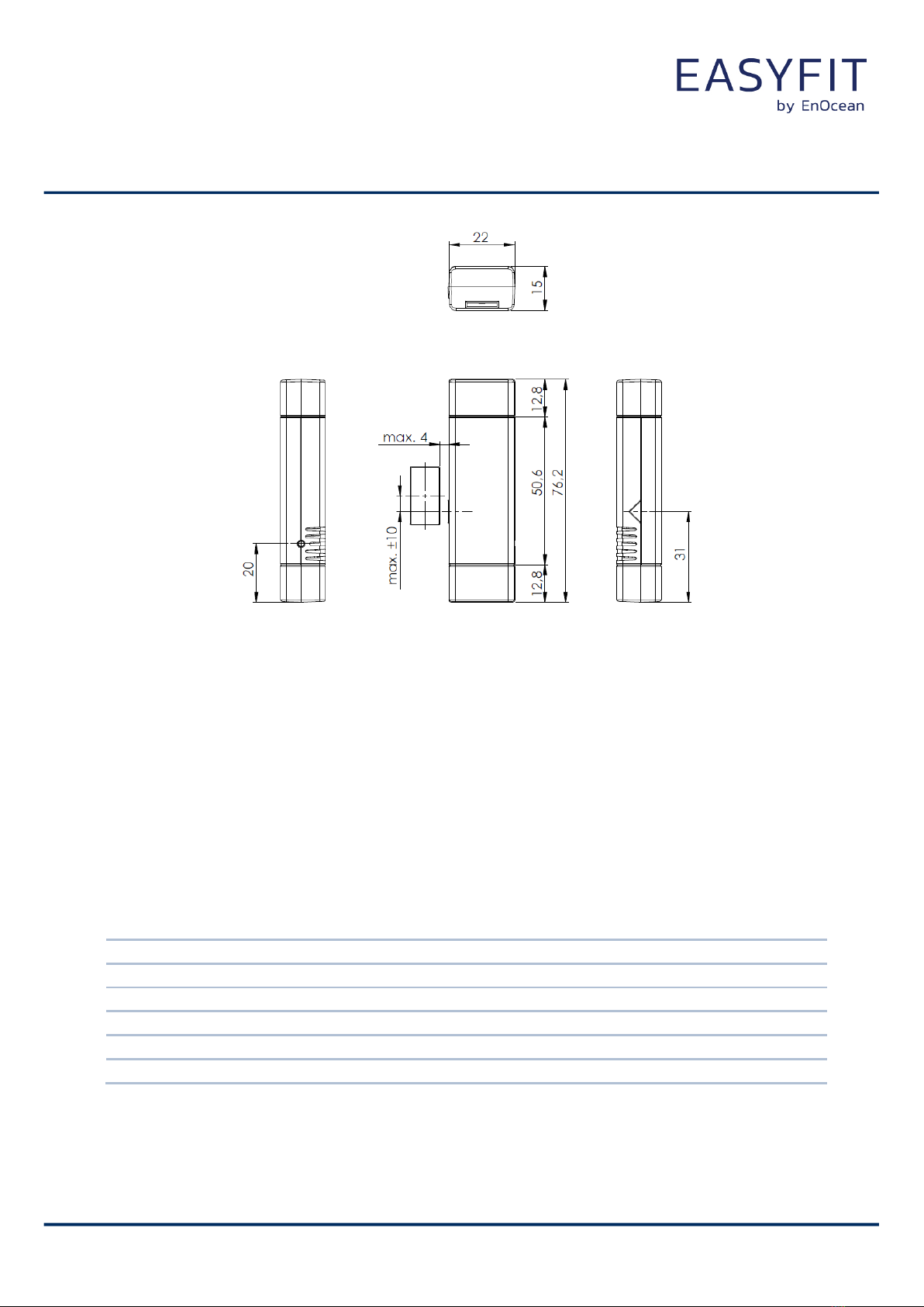
2.5 Physical Dimensions
EMCSx Mechanical Outline (with mounting plate)
Colour of unit housing and mounting plate EMCSA, EMCSU, EMCSJ: White, similar to RAL 9010,
EMCSA-G: Grey, similar to RAL 7016
Material of unit housing and mounting plate PC-ABS (housing), POM (mounting plate)
Dimensions of unit with mounting plate 79 x 23.8 x 18.6 mm
Dimensions of unit without mounting plate 76.2 x 22 x 15 mm
Dimensions of housing adhesive 50 x 18 x 0.8 mm
Dimensions of magnet (incl. adhesive) 20 x 10 x 1.5 mm
USER MANUAL
EMCSA / EMCSU / EMCSJ
ENOCEAN MAGNET CONTACT SENSOR
© 2022 EnOcean | www.enocean.com F-710-017, V1.0 EMCSx User Manual | April 2022 | Page 9/31
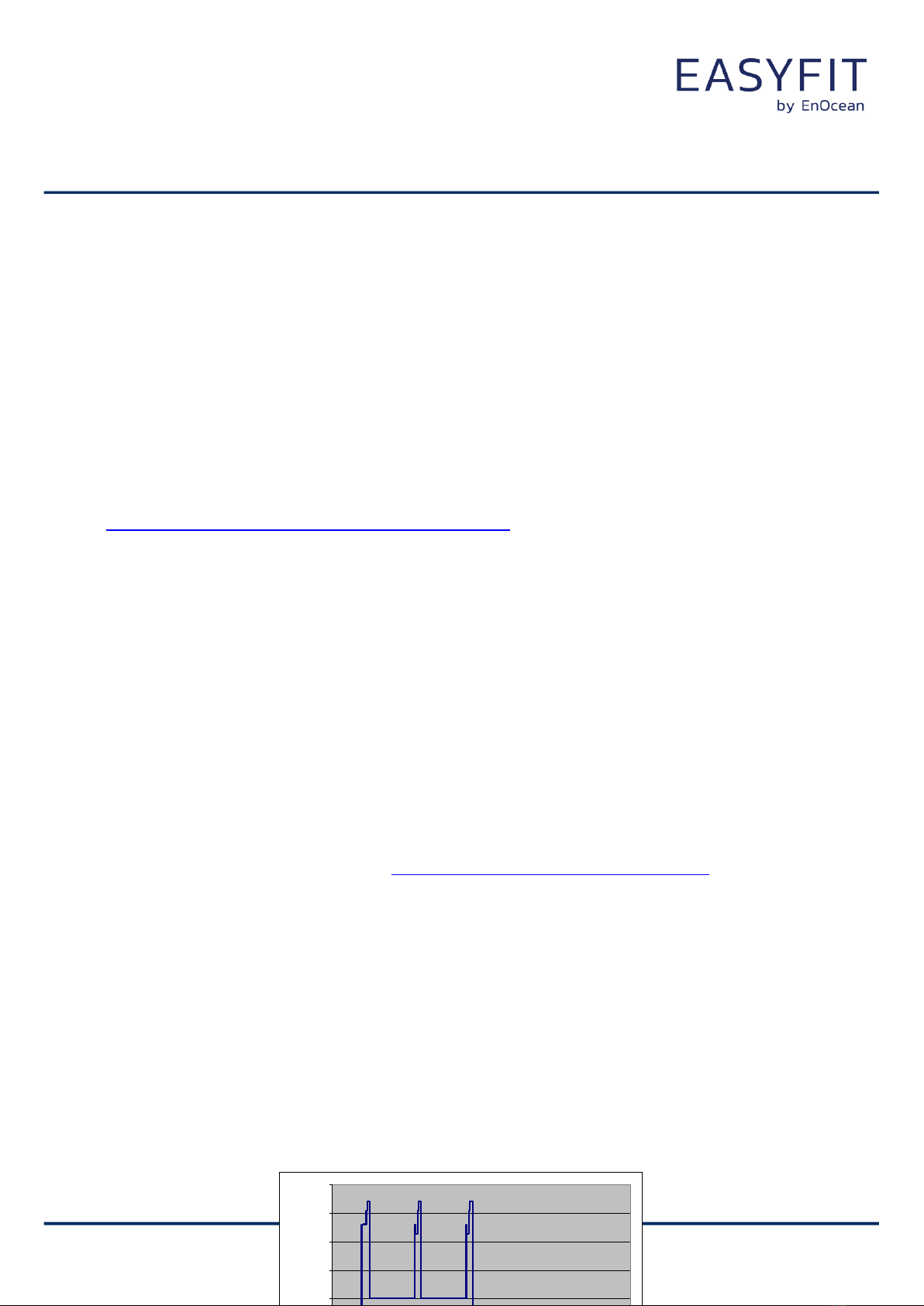
EMCSx Mechanical Outline (without mounting plate)
2.6 Packaging Information –Single Unit Packaging
Content of single unit box:
1. Reed Contact Unit (wireless sensor in housing)
2. Mounting Plate (for mounting the sensor)
3. Adhesive Tape (double-sided, for easy gluing the unit onto a smooth surface)
4. Magnet with adhesive tape (separate in a little plastic bag)
5. Installation Instructions
Weight of sensor unit (without magnet) 20 g
Weight of single unit box (housing, magnet, mounting plate, packaging) 37 g
Size of single unit card box 32 x 32 x 99 mm
Minimum order quantity (transport packaging) 50 units
Dimensions of transport card box (50 single unit boxes) 232 x 176 x 174 mm
Weight of transport box (including 50 single unit boxes) 2.0 kg

USER MANUAL
EMCSA / EMCSU / EMCSJ
ENOCEAN MAGNET CONTACT SENSOR
© 2022 EnOcean | www.enocean.com F-710-017, V1.0 EMCSx User Manual | April 2022 | Page 10/31
Content of single unit box:
Reed Contact, Magnet, Adhesive, Mounting Plate, Instructions
Transport Packaging with 50 single unit boxes
2.7 Packaging Information –Tray Packaging
Card box with 7 plastic trays containing 8 sensor units each, plus 1 tub-tray for the acces-
sories.
Content:
1. 56 Reed Contact Units
2. Mounting Plates (preinstalled at reed contact units)
3. Adhesive Tapes (in separate tray)
4. Magnets with adhesive tape (in separate tray)
Minimum order quantity (transport packaging) 56 units
Dimensions of transport box (56 units) 232 x 176 x 174 mm
Weight of transport box (56 units) 2.2 kg

USER MANUAL
EMCSA / EMCSU / EMCSJ
ENOCEAN MAGNET CONTACT SENSOR
© 2022 EnOcean | www.enocean.com F-710-017, V1.0 EMCSx User Manual | April 2022 | Page 11/31
2.8 Device Label
The structure of the EMCSx device label is shown in the following figure:
Figure: Unit Label
2.8.1 Step Code
The Step Code describes the functional product status of the device and can be found on
the product label between the product ordering code and the unit’s serial number. In the
upper figure the step code is “DA”.
2.8.2 QR-Code
In order to improve logistic and commissioning of the sensor unit a QR code can be found
on the unit label. The QR code used in the new product label encodes the product parame-
ter according to the ANSI/MH10.8.2-2013 industry standard.
Figure: QR Code Example
The QR code shown in the example figure above encodes the following string:
„30S000001234567+30PS3001-C350+2PDA01+S01123456123456“
The following table shows the interpretation of the data therein:
Identifier
Length of data exclud-
ing identifier
Value
Comment
30S
12 characters
ID, Static Source Address
hex
30P
10 characters
Ordering Code
“S3001-C350”
2P
4 characters
Step code and revision
“DA-01”
S
14 characters
Serial Number
Table: QR Code content

USER MANUAL
EMCSA / EMCSU / EMCSJ
ENOCEAN MAGNET CONTACT SENSOR
© 2022 EnOcean | www.enocean.com F-710-017, V1.0 EMCSx User Manual | April 2022 | Page 12/31
3FUNCTIONAL DESCRIPTION
3.1 Block Diagram
A change of the reed contact status or pushing the LRN button will wake the transmitter unit
to send a radio telegram immediately (reed contact position, LRN push button status, unique
32-bit sensor ID, checksum). In addition a redundant retransmission signal is sent to an-
nounce the contact status even in case of no input signal changes. This signal is transmitted
every 20-30 min, affected at random. The transmit indicator LED flashes briefly at every
radio transmission. Between the wake-up phases the device is in sleep mode for minimum
power consumption.
3.2 Teach-in to Receiver Unit
Push the button behind the hole in the side wall to trigger a teach-in telegram. You will see
a LED shining at the housing side as telegram indicator (pay attention to a sufficiently dark
environment).
Figure: Teach-in telegram trigger
Reed Switch

USER MANUAL
EMCSA / EMCSU / EMCSJ
ENOCEAN MAGNET CONTACT SENSOR
© 2022 EnOcean | www.enocean.com F-710-017, V1.0 EMCSx User Manual | April 2022 | Page 13/31
When pressing the LRN key, the module sends a teach-in telegram to a suited receiver ac-
cording to the currently selected communication mode (see chapter 3.3, 4BS teach-in tele-
gram for standard mode, secure teach-in telegram for Secure Mode). The teach-in telegram
identifies the device manufacturer and the function and type of the device via the EEP used.
For EASYFIT devices, EnOcean is set as manufacturer with ID 0x00B.
3.3 Commissioning and Mode Change
The module is shipped in Transport Mode (Mode 3) to switch off the energy store for long
term shelf storage and air cargo. The mode can be changed by pressing the learn button.
Please note that the modes have been changed with Stepcode DE (and later). Make sure that
the solar cell will get enough light for mode change and/or learn telegram.
◼Change from Transport Mode to Standard Mode:
After pressing learn button 1x short (around 1s) the radio module will enter Standard
Mode (Mode 1). A standard learn telegram will be sent and the LED will flash 2x.
◼Change from Standard Mode to Secure Mode:
After pressing learn button 2x long (2x around 5s, pause <1s) the radio module will
enter Secure Mode (Mode 2). A secure learn telegram will be sent and the LED will
flash 2x.
◼Change from Secure or Standard Mode to Transport Mode:
After pressing learn button 1x long (around 5s) the radio module will enter Transport
Mode (Mode 3). A signal telegram will be sent and the LED will flash 3x.
The following diagram illustrates all implemented mode transitions:

USER MANUAL
EMCSA / EMCSU / EMCSJ
ENOCEAN MAGNET CONTACT SENSOR
© 2022 EnOcean | www.enocean.com F-710-017, V1.0 EMCSx User Manual | April 2022 | Page 14/31
Figure: Mode Transitions
The following pushbutton timing is implemented:
•Short press: around 1s (firmware 0.1 –3.0 s)
•Long press: around 5s (firmware 3 –7 s)
•2x long press with very short pause of max. 1 s between
Before changing the operating mode please make sure to clear the device from all
receivers which have been taught to work with this device before. Otherwise the
receiver will ignore the telegrams and the application will not work.
The flag for actual mode itself is stored in non-volatile memory. After power down
reset the previous selected mode is active. The mode change is limited to 50 times.
In normal application scenario only very few are required.
3.4 Radio Telegram Format, EEP
3.4.1 Standard Mode
EMCSx transmits a radio telegram according to EnOcean Equipment Profile EEP D5-00-01 as
defined in the EEP EnOcean Equipment Profiles specification:
www.enocean-alliance.org/eep/
USER MANUAL
EMCSA / EMCSU / EMCSJ
ENOCEAN MAGNET CONTACT SENSOR
© 2022 EnOcean | www.enocean.com F-710-017, V1.0 EMCSx User Manual | April 2022 | Page 15/31
3.4.2 Secure Mode and Secure Telegram (Stepcode DE and later)
In Secure Mode the payload content of the telegram is protected with advanced security
features. Normal operation telegram payload and also teach-in telegram payload both are
protected in the same way. The security features used are defined by the Security Level
Format (SLF). This parameter is set by default to following values:
◼24-bit RLC which starts from 0 at production
◼RLC sent explicitly
◼3-byte CMAC
◼VAES encryption
The security features are added to the communication by encapsulating the payload and
teach-in telegram payload into a secured telegram. The payload itself is not changed and
corresponds to the standard mode payload like defined by EEP D5-00-01. Please refer to the
EnOcean Security Specification for details:
http://www.enocean.com/en/security-specification/
3.4.3 Secure Learn Telegram
In Standard Mode an 1BS teach-in telegram is transmitted by pressing the LRN button. To
process secured communication on a receiver the EMCSx has to send a security teach-in
telegram to the receiver and so inform him about the used security profile, AES key and
initial RLC counter. The security teach-in has to take place before any other communication
can be executed (profile teach-in included). Press the LRN button to trigger the transmission
of the teach-in telegram. The security teach-in and then the profile teach-in are transmitted.
The profile teach-in telegram is already protected by advanced security features. The process
of sending security teach-in telegram and profile teach-in telegram is triggered by pressing
the LRN button in secure mode, the behaviour of the LRN button is following:
1. Button is pressed
2. Security teach-in is send.
3. Profile teach-in is send.
For more information on the structure of the teach-in telegram please refer to chapter 4.2 of
the EnOcean Security Specification: www.enocean.com/security-specification
3.5 Radio Telegram Timing
The setup of the EMCSx transmission timing reliably avoids possible collisions with data pack-
ages of other EnOcean transmitters as well as disturbances from the environment.
3.5.1 Standard Mode Transmission Timing
In Standard Mode with each transmission cycle, 3 identical sub-telegrams are transmitted
within 40 ms. Transmission of a sub-telegram lasts approximately 0.9 ms. The delay between
the three transmission bursts is affected at random.
0.00001
0.0001
0.001
0.01
0.1
1
10
100
010 20 30 40 50 60 70 80 90 100
Time [ms]
Current [mA]

USER MANUAL
EMCSA / EMCSU / EMCSJ
ENOCEAN MAGNET CONTACT SENSOR
© 2022 EnOcean | www.enocean.com F-710-017, V1.0 EMCSx User Manual | April 2022 | Page 16/31
Figure: Transmission timing in Standard Mode
3.5.2 Secure Mode Transmission Timing
In Secure Mode the transmission cycle is reduced to 2 identical sub-telegrams that are trans-
mitted within 20 ms. This compensates the additional energy requirement of enhanced se-
curity computing and additional payload. The transmission of a sub-telegram lasts approxi-
mately 1.2 ms.
3.6 Storing the Rolling Code Counter (RLC)
In Secure Mode the RLC counter needs to be stored in a non-volatile memory. For security
reasons the RLC counter is incremented by every transmitted telegram. Together with the
CMAC the RLC ensures that messages cannot be reproduced or forged. The RLC is stored in
the chip flash memory. To improve the endurance of the flash memory and also the energy
budget not every increment is saved to the non-volatile flash memory. During deep sleep the
RLC is stored in RAM0 memory.
3.7 Energy Consumption / Battery Lifetime
The diagram in chapter 3.4 illustrates a complete cycle in standard mode which starts with
controller active phase (setup, measurement etc.) immediately followed by a telegram trans-
mit. After short sleep phase the controller will get active two times and send two telegrams.
3.7.1 Prerequisites for example calculation
◼Internal energy storage MS412FE with usable capacity of about 0.7 mAh
https://www.sii.co.jp/en/me/datasheets/ms-rechargeable/ms412fe-5/
(voltage range 2.4 - 3 V at 25 °C)
◼Solar cell ECS 200 delivers at 200 lux about 5 µA
https://www.enocean.com/de/enocean-module/details/ecs-300/
◼Power consumption wake-up and transmit cycle standard mode: 100 µAs
◼Power consumption wake-up and transmit cycle secure mode: 140 µAs

USER MANUAL
EMCSA / EMCSU / EMCSJ
ENOCEAN MAGNET CONTACT SENSOR
© 2022 EnOcean | www.enocean.com F-710-017, V1.0 EMCSx User Manual | April 2022 | Page 17/31
◼10 reed contact changes per day (e.g. 5x window open/close)
◼Average leak current of STM 3xy at 25°C: 0.5 uA
◼Wake-up cycle 20 - 25 min (average 1.500 s) for status telegram
◼8 h light per day (24 h) light @ 200 lux and 25°C
3.7.2 Example calculation of the energy consumption
◼Current consumption (depending on amount of wake-ups due to reed contact
change):
•Current consumption for status telegrams and sleep:
100 uAs / 1,500 s + 0.5 uA = 0.57 uA
•Power consumption for 10 reed contact changes incl. additional transmits per
day: 100 uAs / (60 x 60 x 24 s) = 1.2 nA = 0.0012 uA)
•Average current consumption: 0.57 uA
◼Average solar power harvested: 5uA / (8 h / 24 h) = 1.67 uA
◼Time to fully charge energy storage (2.4 to 3.0 V) at stable temperature:
0.7 mAh / (1.67 uA –0.57 uA) = 636 h = 27 days
◼Average operation time in darkness when fully charged (3.0 V to 2.4 V):
0.7 mAh / 0.57 uA = 1,228 h = 51 day
Remarks:
◼Calculation examples and values have tolerances of about +/- 20%.
◼Energy storage performance, power consumption and solar cell performance varies
over temperature.
◼Energy storage performance degrades over lifetime, especially if energy storage is
long time exposed to very high temperatures. High temperatures will accelerate ag-
ing, each 10 K increase from 25°C will half expected life time. Very low temperature
will temporary reduce capacity of energy store and this leads to considerable shorter
dark time operation.
◼Short wake-up cycles (e.g. 1 s) and transmit intervals (e.g. 1 s) significantly reduce
energy storage performance, for this use case an external power supply is recom-
mended.
3.7.3 Consumption in secure mode
Enhanced security mode requires more energy due to encryption algorithm computing time
and extended telegram length because of CMAC. This added consumption is compensated by
reducing the sub-telegram count to 2.
3.7.4 Battery lifetime calculation
Battery lifetime calculation for operation in total darkness (no support by solar cell):
◼Current consumption for status telegrams and sleep: 0.57 uA (= 100 uAs / 1,500 s +
0.5 uA, see 3.6.2)
◼Average current consumption for 100 red contact changes per day = 12.0 nA (= 1.2
nA x 10, according to 3.6.2)
◼CR1225: 48mAh according to data sheet. Assume you can discharge by 90%, 43mAh
are left for use
◼By that CR1225 life time = 43mAh / (0.57 + 0.012) uA = 75438h = 8.6 a
◼You can assume CR1225 self-discharge reduces this number by additional 10%
◼Results in lifetime of EMCSx powered by battery only: 7.8 years

USER MANUAL
EMCSA / EMCSU / EMCSJ
ENOCEAN MAGNET CONTACT SENSOR
© 2022 EnOcean | www.enocean.com F-710-017, V1.0 EMCSx User Manual | April 2022 | Page 18/31
This calculation assumes constant room temperature (22°C). In order to take dynamic effects
into account, the operating characteristics overview in chapter 2.2 indicate at least 5 years.
Please also note, this is an energy balance calculation, early failure of batteries is not con-
sidered. In practical operation, at least some light will be available that enlarges this calcu-
lated lifetime in addition.

USER MANUAL
EMCSA / EMCSU / EMCSJ
ENOCEAN MAGNET CONTACT SENSOR
© 2022 EnOcean | www.enocean.com F-710-017, V1.0 EMCSx User Manual | April 2022 | Page 19/31
4APPLICATION INFORMATION
4.1 General Installation Instructions
The reed contact unit and the magnet are both easily mountable at windows or doorframes
made of aluminum, plastic or wood using the included adhesive pads. Mounting position of
the reed contact unit is horizontal, vertically or even tilted. The reed contact housing offers
protection against splashing water drops. Mounting the reed contact unit on metal surfaces
or aluminum window frames will reduce the radio transmission range. This physical effect is
strongest in extension of the metal surface. So if the unit is mounted on a metal surface
please note that a radio receiver unit should NOT be mounted at the same window front side.
Further important installation notes please find in the Installation Instructions pro-
vided together with the unit.
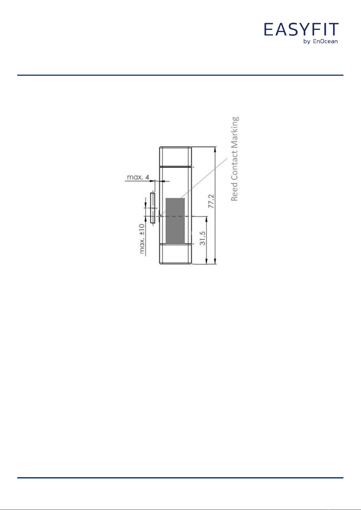
4.2 Magnet Positioning
The very flat magnet can be very easily mounted onto a smooth surface using the preinstalled
adhesive tape. The magnet has to be positioned by facing the housing near to the middle of
the reed contact marking as follows:
USER MANUAL
EMCSA / EMCSU / EMCSJ
ENOCEAN MAGNET CONTACT SENSOR
© 2022 EnOcean | www.enocean.com F-710-017, V1.0 EMCSx User Manual | April 2022 | Page 20/31
Magnet in Righted Position
(Typical for window mounting)
The magnet can be positioned in vertical or in horizontal position to the reed contact housing.
The distance between housing and magnet should be less than 4 mm.
Other manuals for EasyFit EMCSA
1
This manual suits for next models
2
Table of contents
Other EnOcean Accessories manuals

EnOcean
EnOcean 02LINE TRI02SYS User manual

EnOcean
EnOcean ELLS User manual

EnOcean
EnOcean TRIO2SYS User manual

EnOcean
EnOcean Easyfit EMDC User manual

EnOcean
EnOcean EASYFIT STM 550 User manual

EnOcean
EnOcean STM 550X Series User manual

EnOcean
EnOcean STM 350 User manual

EnOcean
EnOcean Easyfit EOSD User manual

EnOcean
EnOcean 02LINE TRI02SYS User manual

EnOcean
EnOcean Easyfit ETHSA User manual


