manuals.online logo
Brands
  1. Home
  2. •
  3. Brands
  4. •
  5. EnOcean
  6. •
  7. Accessories
  8. •
  9. EnOcean Easyfit EMDC User manual

EnOcean Easyfit EMDC User manual

EnOcean BLE Wall Mount Occupancy and Daylight Sensor
430051
Client:
Project Name:
Order #:
Type: Qty:
© Copyright Deco Lighting, Inc. 2019
2917 Vail Ave.
Commerce Ca 90040
Deco Lighting practices a program of continuous product development, and as a result product
specifications change frequently. We reserve the right to change product specifications without
notice. Contact Deco for the latest product information.
[email protected]
t: (800) 613-DECO
f: (310)366-6855
www.getdeco.com
Key Features
Radio Frequency / Standard: 2.4 GHz / Bluetooth Low Energy (Advertising Mode)
Radio Channel: BLE CH 37, 38 and 39 (Advertising Channels)
Transmission Power: +4 dBm
Transmission Range: typ. 75 m outdoor line of sight / 10 m indoor
Recommended Installation: Ceiling-mounted at 2.5m (8.5ft) ... 3m (10 ft) height
Motion Detection Radius: 5 m (16.5 ft.) when installed 2.5 m (8.5 ft.) high
Light Level Sensor: 0 ... 65000 Lux / +- 5% accuracy at full scale
Required Light Level: 200 lux for 6 hours per day
Operation Time Without Light: 96 hours
Backup Battery Type (optional): CR2032
Operation Time With Backup Battery:
Infrequent bright light (200 lux 2 hrs / day)
Consistent low light (65 lux 5 hrs / day)
Total Darkness
20yrs
15yrs
7.5yrs
Product Dimension: 4.46” L x 2.58” W x 1.21” H
Operating Conditions: 0 °C (32 F) ... 60 °C (140 F) Indoor use only
20 % r.h. ... 85 % r.h. Non-condensing
Radio Certification: RED (Europe), FCC (US), ISED (Canada)
Description
EMDC Easyfit motion detection with illumination sensor is a self-powered device that monitors the environment for person-movement using a
passive infrared (PIR) sensor and measures the light level via a dedicated illumination sensor.
Under standard operation conditions, EMDC Easyfit sensor is self-supplied via its solar cell in conjunction with an internal energy store, which enables
the sensor to operate for four days in absolute darkness.
© Copyright Deco Lighting, Inc. 2018
2917 Vail Ave.
Commerce Ca 90040
Deco Lighting practices a program of continuous product development, and as a result product
specifications change frequently. We reserve the right to change product specifications without
notice. Contact Deco for the latest product information.
[email protected]
t: (800) 613-DECO
f: (310)366-6855
www.getdeco.com
Range Diagram
Top View
Wireless sensors and fixtures must be located typically within 33ft (10m) or 246ft (75m) outdoor line of sight.
Sensor Detection Range
Ceiling
Floor
8.5 ft
(2.5 m)
10 ft
(3 m)
10 ft
(3 m)
10 ft
(3 m)
12.5 ft
(3.8 m)
7.5 ft
(2.3 m)
2.5 ft
(0.8 m)
2.5 ft
(0.8 m)
7.5 ft
(2.3 m)
012.5 ft
(3.8 m)
Sensor
Fixture
66 ft
(20 m)
66 ft
(20 m)
© Copyright Deco Lighting, Inc. 2018
2917 Vail Ave.
Commerce Ca 90040
Deco Lighting practices a program of continuous product development, and as a result product
specifications change frequently. We reserve the right to change product specifications without
notice. Contact Deco for the latest product information.
[email protected]
t: (800) 613-DECO
f: (310)366-6855
www.getdeco.com
Installation Instructions:
Tools Required
-Screw Driver
-Backup battery (CR2032) for walk test
Planning
Remove the sensor from its packaging and place it under a bright light for 5 minutes to provide the required
startup charge.
In the meantime, take a moment to plan for the sensor’s successful operation and optimal communication
with other system components.
EMDC is designed for ceiling operation at a recommended height between 2m and 3m (7ft. – 10ft.).
The installation location at the ceiling should be selected such that enough light is available to power the
sensor, that movement can be detected reliably by the PIR sensor and that the wireless signal won’t be
blocked.
The following criteria should be used as guidance for the selection of the installation location:
• Consistent and adequate light should be available for the supply of EMDC via its solar cell (200 lux for 6
hours per day for fully self-supplied operation).
• Consider the area’s traffic patterns and principal use, for example, walking, working, lounging or sleeping
to ensure that motion can be properly detected.
• There must be an unobstructed line of sight to moving persons that shall be detected. Refer also to the
coverage diagram below.
• Motion detection uses the temperature difference between the moving person (body temperature 37°C /
98.5F) and its environment. For proper function it is essential to minimize external effects causing rapid
temperature changes or permanently generating heat that masks such temperature changes.
• Provide a minimum clearance of 4 ft. (1.2 m) away from heat sources, light bulbs, forced air or
ventilation systems and hot moving parts within the detection area that could lead to misdetections
• Avoid installation near ceiling fan or hanging light fixtures that create or distribute heat or might obstruct
the line of sight to the detection area.
• Consider the construction materials (such as metal) in the space and obstacles that may interfere with
RF signals
Installing
Read and understand instructions completely before starting.
1. Select a suitable installation location according to the planning guidelines
2. Remove the wall mount from EMDC using a screwdriver in the opening slot (shown below) to push the
wall mount away from EMDC.
3. If coverage testing (walk test) is required then fit a CR2032 backup battery into the backup battery holder
© Copyright Deco Lighting, Inc. 2018
2917 Vail Ave.
Commerce Ca 90040
Deco Lighting practices a program of continuous product development, and as a result product
specifications change frequently. We reserve the right to change product specifications without
notice. Contact Deco for the latest product information.
[email protected]
t: (800) 613-DECO
f: (310)366-6855
www.getdeco.com
(shown below). This can be removed after test completion.
4. Press the LRN button once and check that the LED blinks once to confirm that EMDC is operational.
5. Learn in EMDC into the desired receiver(s) by using one of the following options:
a. Triggering a Learn telegram by pressing the LRN button once. The LED will blink once to confirm
transmission of the Learn telegram.
b. Scanning the QR code of the device label and using this information to configure the receiver via a
dedicated commissioning tool
c. Reading the device information from the NFC interface of EMDC
6. Attach the wall mount to the intended installation location at the ceiling and place EMDC back onto the
wall mount by gently pushing it towards the ceiling. Consider using a temporary attachment between wall
mount and ceiling until performance at the installation location has been verified.
7. If necessary, perform a walk test to determine the detection range of EMDC. To do so, press the LRN
button twice quickly. EMDC will now flash the LED underneath the PIR lens for a period of 2 minutes
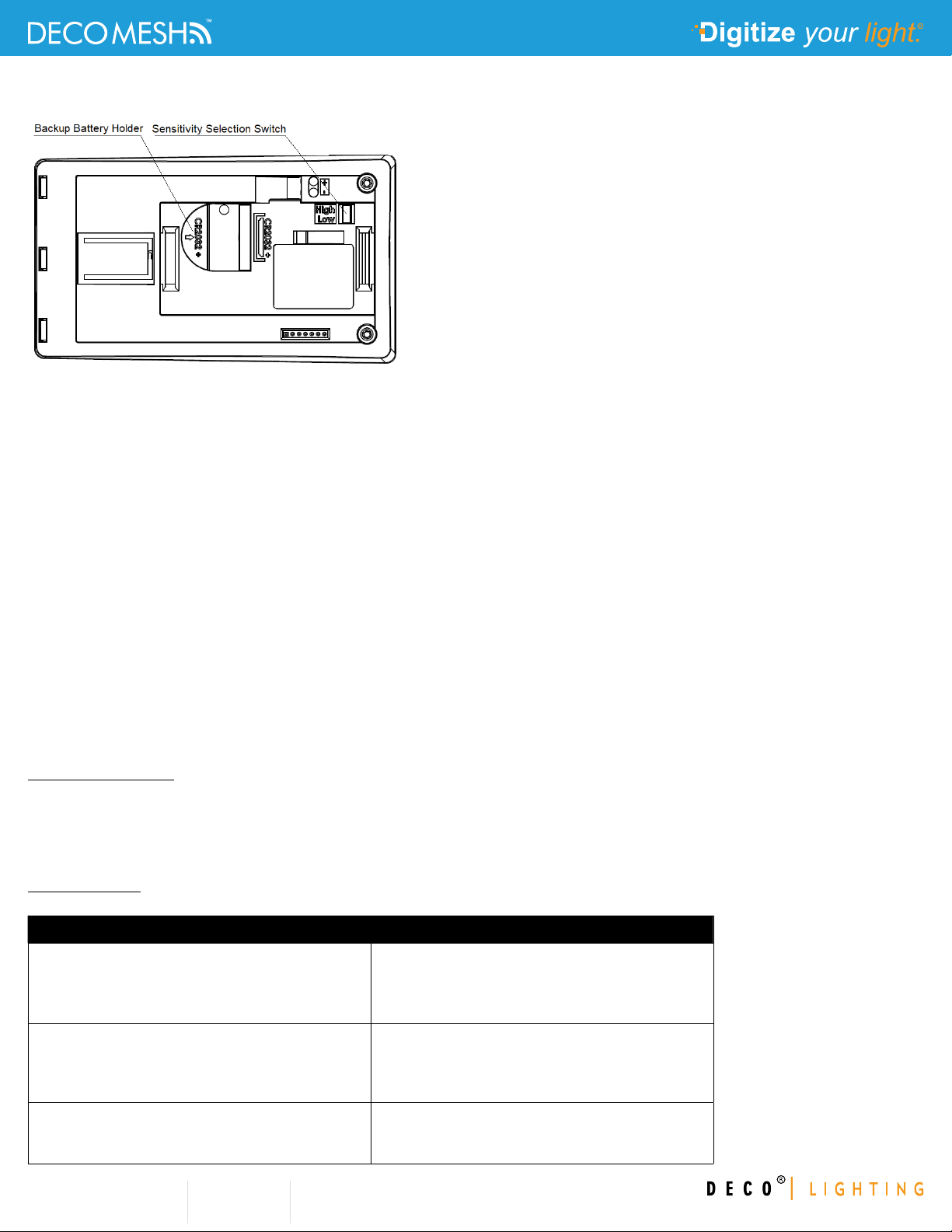
whenever motion is detected. Use of a CR2032 backup battery is recommended for the duration of this test.
8. Adjust the installation location and repeat the walk test if necessary. If the detection range is too large
(e.g. for open offices with corridors) then the sensitivity selection switch allows reducing the detection area.
Device Configuration
EMDC allows enabling and disabling the LED indication via the LRN button.
To do so, triple-click (three clicks in quick succession) the LRN button to toggle the LED indication between
enabled and disabled state. If LED indication is enabled then the LED will blink twice after the triple click; if it
is disabled then the LED won’t blink after the triple click.
Troubleshooting
Use below table for common problems.
Problem Solution Checklist
Sensor does not generate a wireless message • Press LRN button to transmit teach-in message
• Verify the LED blinks when motion is detected
during a walk test
• Verify that the device is charged properly
Sensor is activated when there is nothing to detect • Verify there is 4 ft. (1.2 m) clearance from heat
sources that may disturb sensing
• Reduce sensitivity setting by moving the PIR
sensitivity switch from HI to LO)
Linked device does not respond to wireless
messages
• Verify that a wireless message is sent
• Check for environment or range issues
• Verify that the device is linked

This manual suits for next models

1

Other EnOcean Accessories manuals

EnOcean TRIO2SYS User manual

EnOcean

EnOcean TRIO2SYS User manual

EnOcean 02LINE TRI02SYS User manual

EnOcean

EnOcean 02LINE TRI02SYS User manual

EnOcean EasyFit EMCSA User manual

EnOcean

EnOcean EasyFit EMCSA User manual

EnOcean EasyFit EMCSA User manual

EnOcean

EnOcean EasyFit EMCSA User manual

EnOcean Easyfit STM 550B User manual

EnOcean

EnOcean Easyfit STM 550B User manual

EnOcean EASYFIT EMDCB User manual

EnOcean

EnOcean EASYFIT EMDCB User manual

EnOcean TRI02SYS User manual

EnOcean

EnOcean TRI02SYS User manual

EnOcean STM 550X Series User manual

EnOcean

EnOcean STM 550X Series User manual

EnOcean Easyfit EOSD User manual

EnOcean

EnOcean Easyfit EOSD User manual

EnOcean Easyfit ETHSA User manual

EnOcean

EnOcean Easyfit ETHSA User manual

EnOcean ELLS User manual

EnOcean

EnOcean ELLS User manual

EnOcean EASYFIT STM 550 User manual

EnOcean

EnOcean EASYFIT STM 550 User manual

EnOcean STM 350 User manual

EnOcean

EnOcean STM 350 User manual

EnOcean EOSWU Quick start guide

EnOcean

EnOcean EOSWU Quick start guide

EnOcean EOSC User manual

EnOcean

EnOcean EOSC User manual

EnOcean 02LINE TRI02SYS User manual

EnOcean

EnOcean 02LINE TRI02SYS User manual

Popular Accessories manuals by other brands

Qwik Time QT-5 instructions

Qwik Time

Qwik Time QT-5 instructions

SBS TESTYLUSCAPW manual

SBS

SBS TESTYLUSCAPW manual

Manitowoc K00067 installation instructions

Manitowoc

Manitowoc K00067 installation instructions

Draper AeroLift 25 brochure

Draper

Draper AeroLift 25 brochure

Hubbell Gear Drive Electric Cable Reels SM21 Installation and maintenance instructions

Hubbell

Hubbell Gear Drive Electric Cable Reels SM21 Installation and maintenance instructions

CHIEF Keyboard Tray Accessory KSA1021 installation instructions

CHIEF

CHIEF Keyboard Tray Accessory KSA1021 installation instructions

Garmin nuvi 350 Instructions and rules

Garmin

Garmin nuvi 350 Instructions and rules

Genie Aladdin Connect instruction manual

Genie

Genie Aladdin Connect instruction manual

FRIEDLAND Libra+ manual

FRIEDLAND

FRIEDLAND Libra+ manual

Banner iVu Series manual

Banner

Banner iVu Series manual

Hobo RXW-UC Series quick start

Hobo

Hobo RXW-UC Series quick start

RJG Lynx LES-B-127-50 product manual

RJG

RJG Lynx LES-B-127-50 product manual

DPM WL558W manual

DPM

DPM WL558W manual

Crestron CNCS user guide

Crestron

Crestron CNCS user guide

Fencing SmartBox SmartBox user manual

Fencing SmartBox

Fencing SmartBox SmartBox user manual

Festo SOEG-S-Q20 series manual

Festo

Festo SOEG-S-Q20 series manual

Beper P203TFO110 manual

Beper

Beper P203TFO110 manual

WIKA GD-20 Series operating instructions

WIKA

WIKA GD-20 Series operating instructions

manuals.online logo
manuals.online logoBrands
  • About & Mission
  • Contact us
  • Privacy Policy
  • Terms and Conditions

Copyright 2025 Manuals.Online. All Rights Reserved.