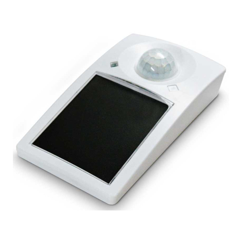
EnOcean EASYFIT STM 550 User manual

USER MANUAL
STM 550 / EMSI –ENOCEAN MULTISENSOR FOR IOT APPLICATIONS
© 2020 EnOcean | www.enocean.com F-710-017, V1.0 STM 550 / EMSI User Manual | v1.3 | September 2020 | Page 1/97
Patent protected:
WO98/36395, DE 100 25 561, DE 101 50 128,
WO 2004/051591, DE 103 01 678 A1, DE 10309334,
WO 04/109236, WO 05/096482, WO 02/095707,
US 6,747,573, US 7,019,241
Observe precautions! Electrostatic sensitive devices!
EnOcean Multisensor For IoT Applications
STM 550 / EMSI
03.09.2020

USER MANUAL
STM 550 / EMSI –ENOCEAN MULTISENSOR FOR IOT APPLICATIONS
© 2020 EnOcean | www.enocean.com F-710-017, V1.0 STM 550 / EMSI User Manual | v1.3 | September 2020 | Page 2/97
REVISION HISTORY
The following major modifications and improvements have been made to this document:
Version
Author
Reviewer
Date
Major Changes
1.0
MKA
TM, EM,
MH, MF
19.02.2020
First public release
1.1
MKA
MKA
18.05.2020
Added description of mechanical interface
Added description of product variants
1.2
MKA
MKA
30.06.2020
Added illustration of backup battery interface
1.3
MKA
MKA
03.09.2020
Added ARIB certificate
Published by EnOcean GmbH, Kolpingring 18a, 82041 Oberhaching, Germany
www.enocean.com, info@enocean.com, phone +49 (89) 6734 6890
© EnOcean GmbH, All Rights Reserved
Important!
This information describes the type of component and shall not be considered as assured
characteristics. No responsibility is assumed for possible omissions or inaccuracies. Circuitry
and specifications are subject to change without notice. For the latest product specifications,
refer to the EnOcean website: http://www.enocean.com.
As far as patents or other rights of third parties are concerned, liability is only assumed for
modules, not for the described applications, processes and circuits.
EnOcean does not assume responsibility for use of modules described and limits its liability
to the replacement of modules determined to be defective due to workmanship. Devices or
systems containing RF components must meet the essential requirements of the local legal
authorities.
The modules must not be used in any relation with equipment that supports, directly or
indirectly, human health or life or with applications that can result in danger for people,
animals or real value.
Components of the modules are considered and should be disposed of as hazardous waste.
Local government regulations are to be observed.
Packing: Please use the recycling operators known to you.

USER MANUAL
STM 550 / EMSI –ENOCEAN MULTISENSOR FOR IOT APPLICATIONS
© 2020 EnOcean | www.enocean.com F-710-017, V1.0 STM 550 / EMSI User Manual | v1.3 | September 2020 | Page 3/97
TABLE OF CONTENT
1General description........................................................................................ 7
1.1 Basic functionality .........................................................................................7
1.2 Product variants ............................................................................................8
1.3 Technical data...............................................................................................9
1.4 Environmental conditions ...............................................................................9
1.5 Packaging information.................................................................................. 10
1.5.1 STM 550 ............................................................................................. 10
1.5.2 STM 550 installation kit ........................................................................ 10
1.5.3 EMSI .................................................................................................. 10
1.6 Ordering information ................................................................................... 10
2Functional overview ..................................................................................... 11
2.1 Product description ...................................................................................... 11
2.2 Functional modes ........................................................................................ 11
2.2.1 Standard operation mode ..................................................................... 12
2.2.2 Standby (Sleep) mode.......................................................................... 12
2.2.3 Learn mode......................................................................................... 12
2.2.4 Function test mode .............................................................................. 12
2.2.5 Illumination test mode ......................................................................... 13
2.2.6 Acceleration test mode ......................................................................... 13
2.2.7 Factory reset mode .............................................................................. 13
2.3 Reporting interval........................................................................................ 14
2.3.1 Energy considerations .......................................................................... 14
2.3.2 Standard reporting interval ................................................................... 15
2.3.3 Illumination-controlled reporting interval ................................................ 16
2.3.4 Temperature-controlled reporting interval ............................................... 17
2.3.5 Humidity-controlled reporting interval .................................................... 18
2.3.6 Acceleration-controlled reporting interval ................................................ 19
2.3.7 Magnet contact sensor-controlled reporting interval ................................. 20
2.3.8 Arbitration between reporting intervals................................................... 20
3Sensor functionality ..................................................................................... 21
3.1 Light level sensor ........................................................................................ 21
3.2 Solar cell .................................................................................................... 21
3.3 Temperature sensor..................................................................................... 22
3.4 Humidity sensor .......................................................................................... 22
3.5 Acceleration sensor...................................................................................... 23
3.5.1 Wake on acceleration ........................................................................... 24
3.5.2 Acceleration sensor parameters ............................................................. 24
3.6 Magnet contact sensor ................................................................................. 25
4Product interface ......................................................................................... 26
4.1 LED ........................................................................................................... 27
4.2 LRN button ................................................................................................. 27
4.3 Backup battery ........................................................................................... 28
4.3.1 Safety remarks.................................................................................... 28
4.4 Product label............................................................................................... 29

USER MANUAL
STM 550 / EMSI –ENOCEAN MULTISENSOR FOR IOT APPLICATIONS
© 2020 EnOcean | www.enocean.com F-710-017, V1.0 STM 550 / EMSI User Manual | v1.3 | September 2020 | Page 4/97
5Radio communication................................................................................... 30
5.1 Radio Frame format ..................................................................................... 30
5.1.1 ERP1 frame format .............................................................................. 30
5.1.2 ERP2 frame format .............................................................................. 30
5.2 EnOcean Equipment Profiles (EEP) and SIGNAL telegrams ................................ 31
5.2.1 STM 550 supported EEP........................................................................ 31
5.2.2 EEP structure ...................................................................................... 32
5.2.3 1BS telegram ...................................................................................... 33
5.2.4 4BS telegram ...................................................................................... 33
5.2.5 VLD telegram ...................................................................................... 33
5.2.6 UTE (Universal Teach-in) telegram......................................................... 33
5.2.7 Signal telegram ................................................................................... 34
6Security ..................................................................................................... 35
6.1 Basic concepts ............................................................................................ 35
6.1.1 Telegram encryption ............................................................................ 35
6.1.2 Telegram authentication ....................................................................... 36
6.1.3 Dynamic security key modification ......................................................... 37
6.2 Security parameters .................................................................................... 38
6.2.1 EURID ................................................................................................ 38
6.2.2 Security key........................................................................................ 38
6.2.3 Rolling code ........................................................................................ 38
6.2.4 Security algorithm ............................................................................... 38
6.3 STM 550 security implementation.................................................................. 39
7Commissioning............................................................................................ 40
7.1 Radio-based commissioning.......................................................................... 41
7.2 QR code commissioning ............................................................................... 41
7.3 Commissioning via NFC interface................................................................... 41
8NFC interface .............................................................................................. 42
8.1 NFC interface parameters ............................................................................. 42
8.2 NFC access protection .................................................................................. 42
8.3 Using the NFC interface................................................................................ 43
8.3.1 PC with dedicated NFC reader ............................................................... 43
8.3.2 Android or iOS smartphone with NFC...................................................... 43
8.4 NFC interface functions ................................................................................ 44
8.4.1 NFC interface state machine.................................................................. 44
8.4.2 IDLE state........................................................................................... 45
8.4.3 READY 1 state ..................................................................................... 45
8.4.4 READY 2 state ..................................................................................... 45
8.4.5 ACTIVE state....................................................................................... 45
8.4.6 Read command ................................................................................... 46
8.4.7 Write command ................................................................................... 46
8.4.8 Password authentication (PWD_AUTH) command..................................... 47
9NFC registers .............................................................................................. 48
9.1 NFC memory areas ...................................................................................... 48
9.2 Device identification NDEF ............................................................................ 49
9.3 User information NDEF................................................................................. 49

USER MANUAL
STM 550 / EMSI –ENOCEAN MULTISENSOR FOR IOT APPLICATIONS
© 2020 EnOcean | www.enocean.com F-710-017, V1.0 STM 550 / EMSI User Manual | v1.3 | September 2020 | Page 5/97
9.4 NFC HEADER............................................................................................... 50
9.4.1 NFC HEADER area structure .................................................................. 50
9.5 CONFIGURATION......................................................................................... 51
9.5.1 Using the NFC configuration functionality ................................................ 51
9.5.2 CONFIGURATION area structure ............................................................ 51
9.5.3 NFC_PIN_CODE ................................................................................... 52
9.5.4 PRODUCT_ID ...................................................................................... 52
9.5.5 USER_KEY .......................................................................................... 53
9.5.6 SECURITY_KEY_MODE.......................................................................... 53
9.5.7 SECURITY_MODE................................................................................. 54
9.5.8 EEP.................................................................................................... 55
9.5.9 SIGNAL .............................................................................................. 56
9.5.10 LED_MODE ......................................................................................... 57
9.5.11 FUNCTIONAL_MODE............................................................................. 58
9.5.12 STANDARD_TX_INTERVAL .................................................................... 59
9.5.13 THRESHOLD_CFG1............................................................................... 60
9.5.14 THRESHOLD_CFG2............................................................................... 62
9.5.15 LIGHT_SENSOR_CFG ........................................................................... 63
9.5.16 ACC_SENSOR_CFG .............................................................................. 64
9.5.17 SOLAR_THRESHOLD............................................................................. 65
9.5.18 SOLAR_TX_INTERVAL .......................................................................... 66
9.5.19 LIGHT_THRESHOLD ............................................................................. 67
9.5.20 LIGHT_TX_INTERVAL ........................................................................... 68
9.5.21 ACCELERATION_THRESHOLD ................................................................ 69
9.5.22 ACCELERATION_TX_INTERVAL .............................................................. 70
9.5.23 TEMPERATURE_THRESHOLD ................................................................. 71
9.5.24 TEMPERATURE_TX_INTERVAL ............................................................... 72
9.5.25 HUMIDITY_THRESHOLD........................................................................ 73
9.5.26 HUMIDITY_TX_INTERVAL...................................................................... 74
9.5.27 MAGNET_CONTACT_TX_INTERVAL......................................................... 75
9.5.28 ILLUMINATION_TEST_RESULT............................................................... 76
9.6 USER DATA ................................................................................................ 76
10 Mechanical interface .................................................................................... 77
10.1 Top view .................................................................................................... 77
10.2 Bottom view ............................................................................................... 78
10.3 Cut view (A-A) ............................................................................................ 79
10.4 Front view .................................................................................................. 79
10.5 Side view ................................................................................................... 80
11 Installation recommendations ....................................................................... 81
11.1 Setup instructions ....................................................................................... 81
11.2 Temperature and humidity sensor ................................................................. 82
11.3 Acceleration sensor...................................................................................... 83
11.3.1 Device orientation use cases ................................................................. 83
11.3.2 Device acceleration use cases................................................................ 85
11.3.3 Installation suggestions ........................................................................ 85
11.4 Illumination measurement ............................................................................ 86
11.4.1 Ambient light sensor ............................................................................ 86
11.4.2 Solar cell ............................................................................................ 86
This manual suits for next models
9
Table of contents
Other EnOcean Accessories manuals
EnOcean
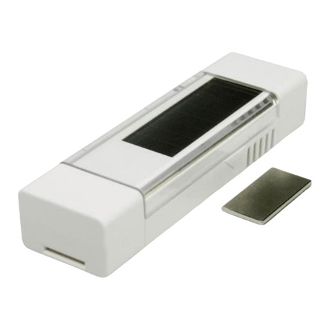
EnOcean EasyFit EMCSA User manual

EnOcean
EnOcean ELLS User manual
EnOcean
EnOcean 02LINE TRI02SYS User manual
EnOcean
EnOcean Easyfit STM 550B User manual

EnOcean
EnOcean EasyFit EMCSA User manual
EnOcean
EnOcean Easyfit ETHSA User manual
EnOcean
EnOcean Easyfit EMDC User manual
EnOcean
EnOcean EOSWU Quick start guide
EnOcean
EnOcean TRI02SYS User manual
EnOcean
EnOcean STM 350 User manual
