Enotec AQUATEC 1000 User manual
Doc.-ID: AQUA_16012020_EN
Installation and Operation Manual
O
2
and water vapor analyzer system
AQUATEC
®
1000
Version 04
for Software Version: 4.10
ENOTEC GmbH
Process and Environmental
Measuring Technology
DIN EN ISO 9001
Höher Birken 6
D-51709 Marienheide
Germany
Tel.: +49 (0) 2264 - 45 78 0
Fax: +49 (0) 2264 - 45 78 31
Internet: www.enotec.com
Preface
Dear Customer,
For many years now, our AQUATEC
®
1000 oxygen and water vapor analyzer systems have been operating in numerous
applications with many thousand units being produced and shipped around the world. ENOTEC are committed to total quality
and performance and we have continuously enhanced our products to integrate various additional features and functions. In this
package, the electronic unit uses the very latest Microprocessor Technology permitting you to reduce your maintenance & fuel
costs, and to achieve increased measuring accuracy with more operational reliability using these monitoring functions.
In our oxygen measuring probes you will find that the Zirconium Oxide measuring cell is soldered in place using a special
process and technique developed by our company. This results in a considerably increased service life compared to "glued or
cemented" measuring cells, which have a tendency to leak or crack during operation. The Zirconium Oxide measuring cell has a
proven gas-tight design, providing greater measuring accuracy, durability and longer working life.
All ENOTEC instruments are thoroughly tested in the factory and are subject to a strict ISO 9001 Quality Assurance procedure.
Therefore, with the correct installation, the operation of the AQUATEC
®
1000 oxygen and water vapor analyzer system is very
easy and user friendly and will provide you with many years of operation with perfect measuring results.
Symbols used in this Manual
All symbols listed beneath, attached to the analyzer or noted in this manual show important information as well as safety
instructions for installation, operation and maintenance, to protect the personnel and the equipment.
Warning
Follow all instructions of this manual
Consider Information
Points out important information which must be
considered before execution
Warning hot Surface
Warns of danger of burns which could occur from
hot system parts
Note
Contains further detailed information
Caution
Warns of risks of destroying the system or its
components or its functionality
Ground earth electrical protection
The contents of this manual are protected by copyright. Alterations and errors reserved.
Safety Instructions
The System is operated with line voltage. After removal of terminal covers some parts of this system may be accessible which
are under high line voltage.
Only well trained and authorized personnel are allowed to work on this system. The personnel must know and understand all
precautions, safety instructions, installation and maintenance instructions of this manual. The trouble free and safe operation
of the system requires safe transportation, professional storage, installation, operation and maintenance.
Furthermore all local safety requirements at the point of installation and operation must be considered.
This analyzer may not be used to measure oxygen in combustible gases or in an environment with combustible gases. Parts of
this system may cause an explosion risk.

Installation and Operation Manual – AQUATEC 1000 Table of Contents
Doc.-ID: AQUA_16012020_EN 3
Table of Contents
1System Description 4
1.1System Overview ................................................4
1.2Measuring Principle.............................................6
1.3Measuring Principle Water Vapor........................6
1.4Intended use .......................................................6
1.5Safety Hazards....................................................6
1.6Disruption of the Process ....................................7
1.7Storage instructions ............................................7
1.8Name Plates .......................................................7
2Installation 8
2.1Installation Requirements for Electronic Unit ......8
2.2Installation of Probe Signal Cable FEP-0001 ......9
2.3Access to the Terminals....................................10
2.4Ferrite Sleeves (EMC).......................................10
2.5Wiring Diagram of the Electronic Unit ...............11
2.6AQUATEC® 1000 Wiring diagram ....................12
2.7Installation of the probe.....................................13
2.8Mounting of the Probe.......................................13
2.9Adjusting the V-shield / filter head.....................14
2.10Electrical Connections of the Probe ..................15
2.11Requirements for Pneumatic Tube FEP-0002 ..15
2.12Preparation of the pneumatic Tube ...................16
2.13Gas plans..........................................................16
2.14Pneumatic Connections of the Probe................16
2.15Pneumatic Connections of the Electronic Unit ..17
3Initial Operation 18
3.1Checklist before commissioning the system .....18
3.2System Power Up .............................................18
3.3Display - Probe Heating Phase .........................18
3.4Display - Measuring Mode ................................18
3.5Keypad and Display ..........................................19
3.6Status LEDs ......................................................19
3.7Softkey Symbols ...............................................19
3.8System Code.....................................................19
3.9Adjustment of the Analyzer to the Dryer............19
4Software Overview and Explanations 20
4.1Menu Overview - SYS-MENU ...........................20
4.2Software Explanations - SYS-MENU ................23
4.2.1O2Measuring Ranges (Scaling)........................23
4.2.2Measuring value averaging for .......................... 23
4.2.3mA output on system errors ..............................23
4.2.4O2limit alarm settings .......................................23
4.2.5O2Sensor calibration values ............................. 24
4.2.6Time per test gas apply.....................................24
4.2.7Delay time to process........................................24
4.2.8Automatic Calibration (ACAL) ...........................24
4.2.9Automatic Calibration Settings ..........................24
4.2.10Bluetooth...........................................................25
4.2.11Measuring units.................................................25
4.2.12Language ..........................................................25
4.2.13Change system code ........................................25
4.2.14Load factory settings .........................................25
4.2.15Service (Factory Service Settings) .................... 25
4.3Calibration Menu ............................................... 26
4.3.1Calibration Menu - Display Overview ................ 26
4.3.21-point calibration (manual) .............................. 27
4.3.32-point calibration (manual) .............................. 27
4.4System Checks................................................. 28
5Service and Maintenance 29
5.1Exchange fuses ................................................ 29
5.2Flow rates for Test Air and Reference Air ......... 29
5.3Adjusting Flow Rate (integrated Pneumatics) ... 30
5.4Position of the adjustment valves ..................... 31
5.5Replacing the Filter ........................................... 31
5.5.1Remove old Filter.............................................. 31
5.5.2Cement in new Filter ......................................... 32
5.6Replacing the probe.......................................... 32
5.7Replacing the O2Sensor .................................. 33
5.8Exchange of Probe Inner Parts......................... 34
5.9Exchange of Thermocouple Element................ 34
5.10Exchange of Heating Element .......................... 35
5.11Exchange of Signal Measuring Wire................. 35
5.12Exchange of 4-Hole Ceramic Rod .................... 35
5.13Relay Outputs / Functions and Correlation ....... 36
5.14Digital Inputs ..................................................... 37
5.15Stability Criteria for Calibration ......................... 37
5.16Reaction Time of the mA Output....................... 37
5.17Extension Modules............................................ 37
6Status Messages 38
6.1Error Messages ................................................ 38
6.2Alarm Messages ............................................... 39
6.3Maintenance Messages .................................... 39
7Troubleshooting 40
ATechnical Data 41
A.1Technical Specifications - Electronic Unit ......... 41
A.2Technical Specifications - Probe....................... 42
A.3Gas Supply - Systems with Instrument Air........ 43
BDimensional drawings 44
B.1Dimensions of Electronic Unit Housing versions44
B.2Probe Dimensions ............................................ 44
B.3Counter Flange Dimensions ............................. 45
B.4Dimensions of protection tube flanges .............. 46
CSpare Parts 47
C.1Probe Components - KES-132X ....................... 47
C.2Probe inner parts assembly .............................. 48
C.3Mounting Plates of the Electronic Unit .............. 49
C.4Display Board ................................................... 50
DWarranty 51
EDeclaration of Conformity 52
Index 53
System Description Installation and Operation Manual – AQUATEC 1000
4 Doc.-ID: AQUA_16012020_EN
1 System Description
1.1 System Overview
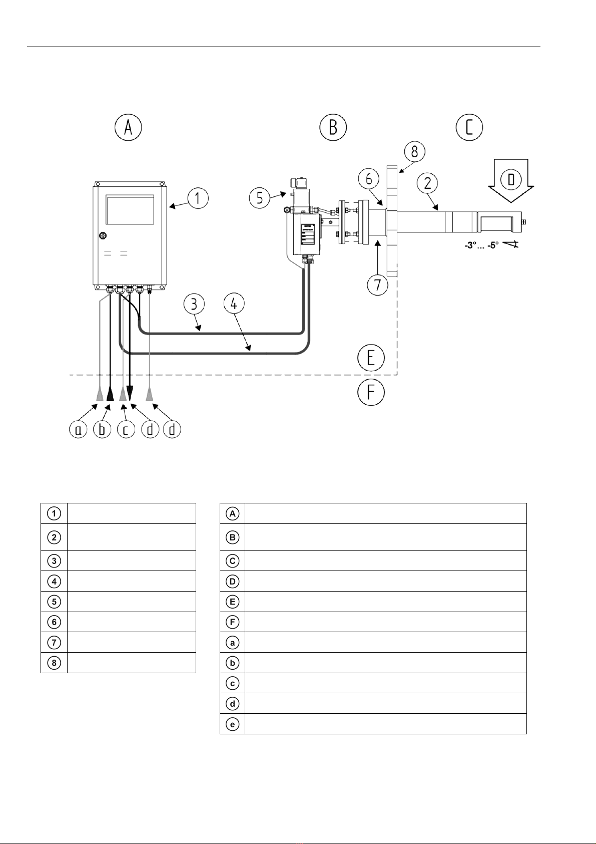
Figure 1 - AQUATEC 1000 analyzer system with active carbon filter
Electronic unit SME5 / IP66 Safe Area - Max. ambient temp.:-20°C to +55°C (-4°F to + 131°F)
In-situ measuring probe /
IP65
Safe Area - Max. ambient temp.:-20°C to +80°C (-4°F to + 167°F)
Pneumatic cable Process
O
2
probe signal cable Process gas direction – max. flue gas temp. 200 °C (392 °F)
Solenoid valve (Optional) Manufacturer supply
Counter flange (Optional) Customer supply
Isolation: Customer Test gas in
Duct wall Power supply
Instrument air in (Reference air in for pump systems)
Output signals (analog and digital)
Test air in (only for pump systems)
Installation and Operation Manual – AQUATEC 1000 System Description
Doc.-ID: AQUA_16012020_EN 5
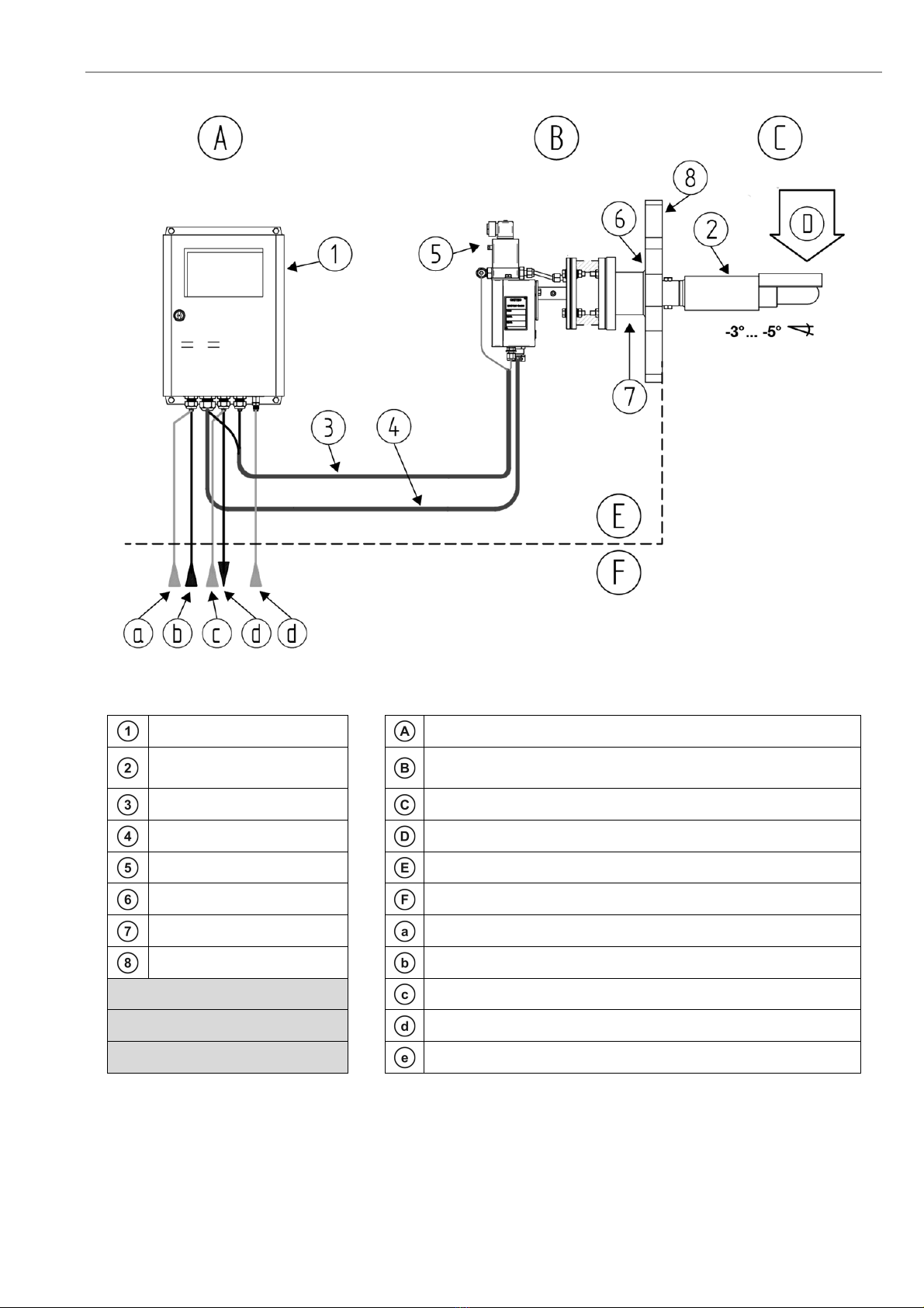
Figure 2 - AQUATEC 1000 analyzer system with standard filter
Electronic unit SME5 / IP66 Safe Area - Max. ambient temp.:-20°C to +55°C (-4°F to + 131°F)
In-situ measuring probe /
IP65
Safe Area - Max. ambient temp.:-20°C to +80°C (-4°F to + 167°F)
Pneumatic cable Process
O
2
probe signal cable Process gas direction – max. flue gas temp. 400 °C (752 °F)
Solenoid valve (Optional) Manufacturer supply
Counter flange (Optional) Customer supply
Isolation: Customer Test gas in
Duct wall Power supply
Instrument air in (Reference air in for pump systems)
Output signals (analog and digital)
Test air in (only for pump systems)
System Description Installation and Operation Manual – AQUATEC 1000
6 Doc.-ID: AQUA_16012020_EN
1.2 Measuring Principle
The AQUATEC
®
1000 O
2
/ H
2
O analyzer system consists of an in-situ probe which is installed in a process to
measure non-combustible process gases and of an electronic unit for voltage and gas supply, as well as for signal
processing.
The oxygen sensor is at the tip of the probe and is regulated to 800 °C and works on the zirconium oxide principle of
measurement. Here, a mV signal between the reference gas side of the sensor (inside, instrument air 20.95% O2)
and the measured gas side is measured, which depends logarithmically on the ratio of oxygen partial pressures on
both sides of the sensor.
The mV signal is converted according to the Nernst equation into oxygen partial pressure within the process gas,
whereby the O
2
concentration is determined in the process gas. Gas-tight separation of reference air and process
gas is of particular importance.
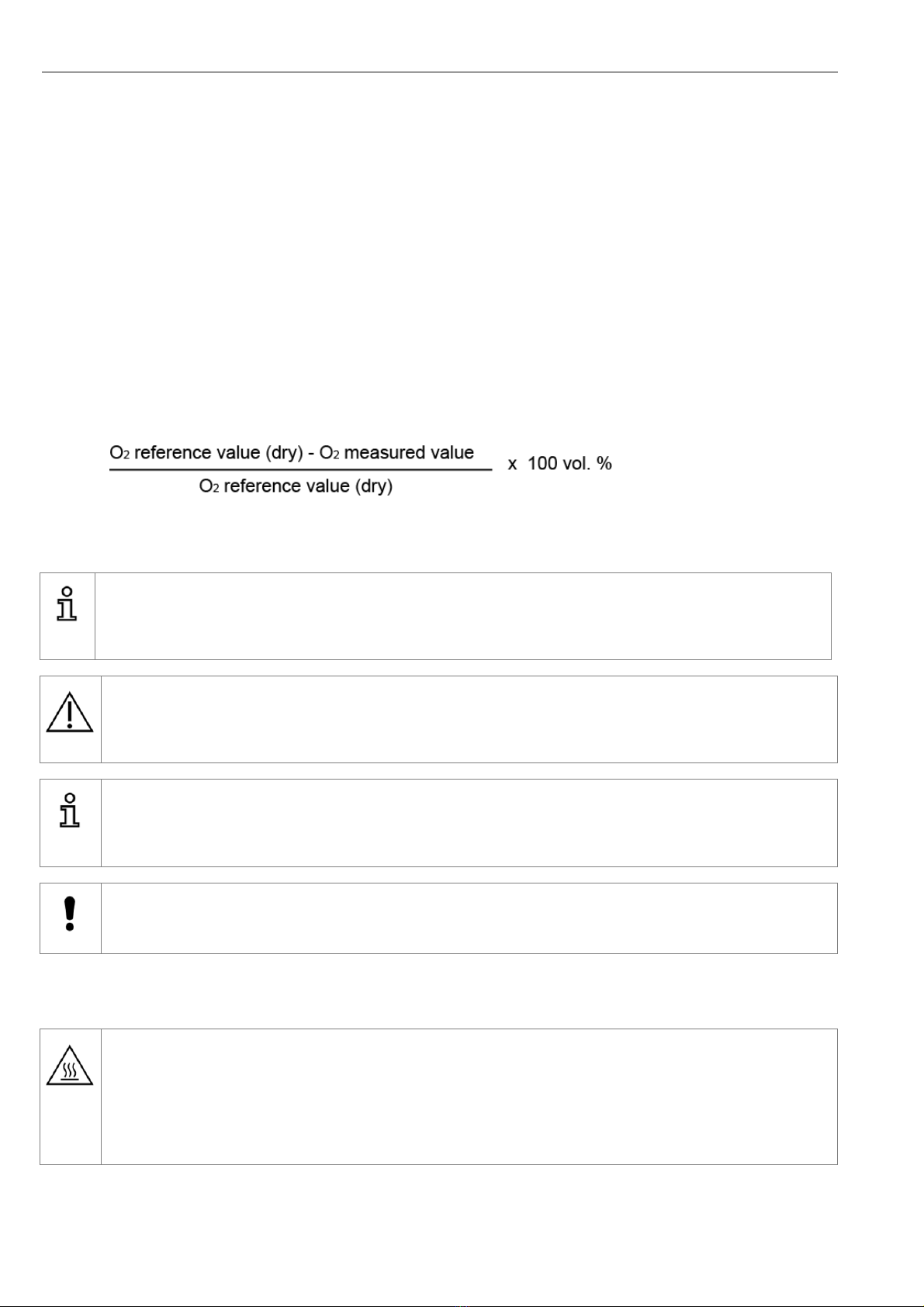
1.3 Measuring Principle Water Vapor
The AQUATEC 1000 does not measure water vapor directly, but calculates it using the measured oxygen content.
The water vapor concentration is proportional to the quantity of the displaced oxygen.
The formula for water vapor evaluation is represented as follows (see chapter 3.9 for details):
1.4 Intended use
Info
The AQUATEC
®
1000 analyzer system is a system for measuring the oxygen (O
2
) concentration in non-combustible
process gases and to calculate the water vapor content (H
2
O) using the oxygen concentration.
Warning
The system cannot be used to determine the oxygen concentration of combustible gases or in a location where
combustible gases are present as the measuring cell temperature of 800°C could present an explosion hazard!
Info
The minimum concentration of O
2
in flue gas should under normal process conditions, not be less than 0,5%.
If the O
2
concentration is regularly below 0,5%, we recommend the option of CSP (Cell Surface Protection) to
protect the O
2
sensor
.
Caution
Under no circumstance should the measuring probe be directly connected to the 230V main power supply, as this will
immediately destroy the probe heater element!
1.5 Safety Hazards
Warning hot surface
During operation, the temperature of the probe filter head and of other parts exposed to flue gas is 150°C - 800°C
(302°F - 1472°F). Direct contact with the hot parts when dismantling or maintenance will cause severe burns!
The probe may only be removed with heat-insulated gloves. Before removing the probe, always switch off the supply
voltage of the electronic system. After removal, store the probe in a safe, protected place and wait until it has cooled
down below 35°C (95°F).
Installation and Operation Manual – AQUATEC 1000 System Description
Doc.-ID: AQUA_16012020_EN 7
1.6 Disruption of the Process
The analyzer system has to be kept in operation also in the event of the process being disrupted or if the plant is
powered off temporarily (e.g. at night or during the weekend). Frequently cooling down and heating up of the probe
results in thermal stress of the hot probe parts (heater, thermocouple and sensor) and reduces their product life.
ENOTEC will not accept any responsibility for resultant damage.
1.7 Storage instructions
ENOTEC equipment is to be stored in a dry and ventilated environment. Paint fumes, silicone sprays, etc. must be
avoided in the storage environment.
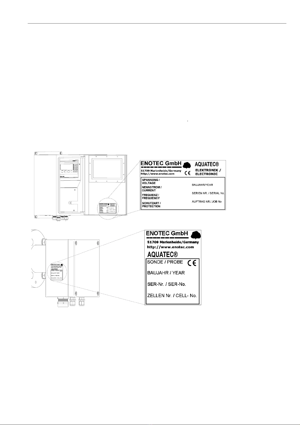
1.8 Name Plates
The name plate contains information about the line voltage, the nominated current, frequency, protection class, year
of manufacture, serial number, order number and system order code.
The system order code refers to information which is detailed in the system test report and supplied with the system.
SME-53 Electronic Unit
Probe Connection Box
Figure 3 - Position of the name plates

Installation Installation and Operation Manual – AQUATEC 1000
8 Doc.-ID: AQUA_16012020_EN
2 Installation
Warning
The system is not equipped with an external power-off switch. The line voltage switch/fuse/breaker must be installed
and be in accordance with local technical standards and should be near to the electronic unit and must be clearly
marked as such. The probe cable is suitable for an ambient temperature range from -40°C to +90°C. All other
installed cables must be suitable for the ambient temperature range at side and must have the required size. All
electronic unit terminals are specified from 0,08 mm² (AWG 26) to 2,5 mm² (AWG 14). If wire end ferrules are used
the next smaller size is required. Before removal of the electronic terminal cover the line voltage must be switched off.
The line voltage to the electronic unit must be switched on again after the cover is back in position. After installation
power conducting parts may not be accessible.
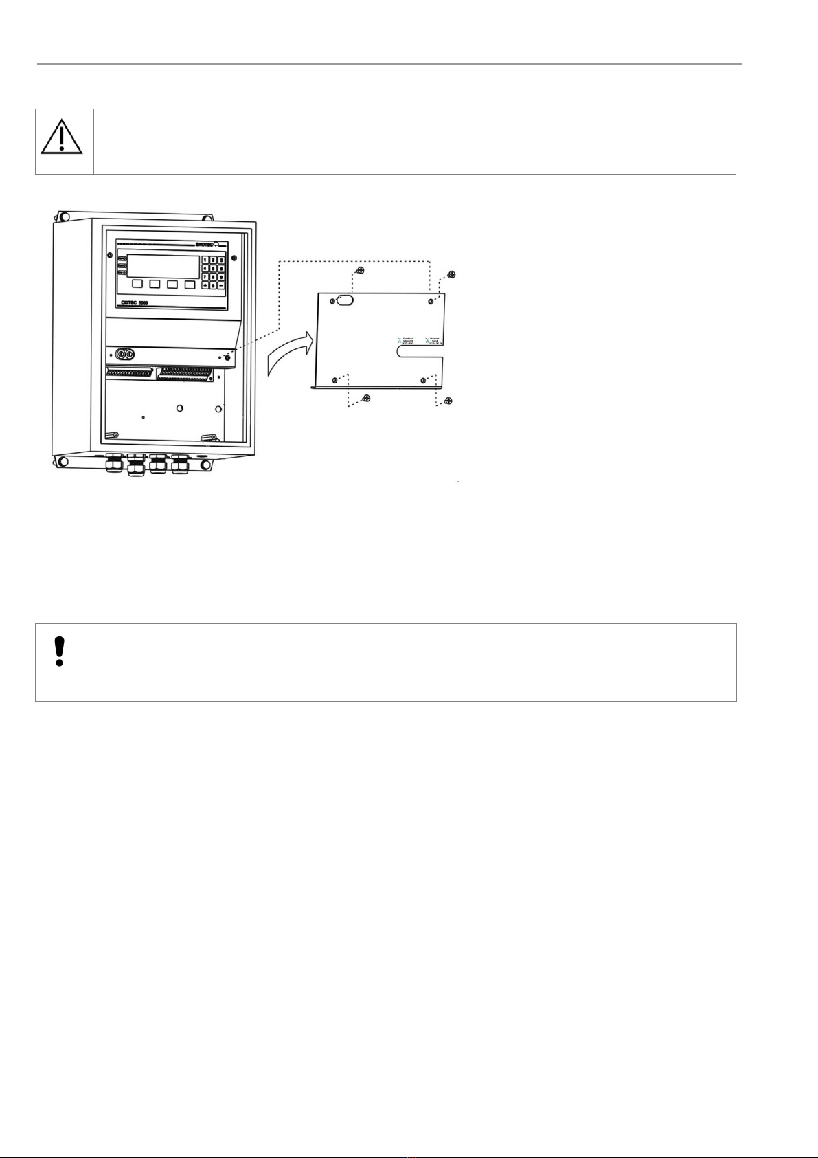
2.1 Installation Requirements for Electronic Unit
Keep the minimum distance to adjacent objects
Install at eye level
Avoid vibrations greater than 2g
Mind the IP code
Heavy equipment,
ensure proper lifting
and carrying
Ambient temperatures
Min.: -20 °C (-4 °F) / Max.: +55 °C (+131 °F) - (Pump version -20 °C to +50 °C)
Drill holes for the electronic unit
Use suitable screws
Electronic unit
Figure 4 - Installation of the Electronic unit

Installation and Operation Manual – AQUATEC 1000 Installation
Doc.-ID: AQUA_16012020_EN 9
2.2 Installation of Probe Signal Cable FEP-0001
Abide by the maximum cable length (max. 150m)
Note the minimum bending radius.
FEP-0001 R
min
= 96 mm
Temp. during installation
Temp. during operation
Cross the probe signal cable (FEP-0001) at right angle
to power supply cables
Figure 5 - Probe cable FEP-0001
Probe Cable FEP-0001 (FEP-0004 armored version)
No. Function Diameter Colors Additional info.
Measuring cell 2 x 0,75 mm
2
white-brown / brown With shield
Thermocouple 2 x 0,75 mm
2
green / white With shield
Probe heating 3 x 1,5 mm
2
black / blue / green-
yellow
Solenoid valve 2 x 0,75 mm
2
grey / grey-blue
Caution
The shield of the probe cable must only be connected at the electronic housing at the PE terminal. Under no
circumstance should the shield also be connected at the probe.
-
5 °C
Min.
+50 °C
Max.
-40 °C
Min.
+90 °C
Max.
Installation Installation and Operation Manual – AQUATEC 1000
10 Doc.-ID: AQUA_16012020_EN
2.3 Access to the Terminals
Warning
Before removing the terminal covers, switch off the mains voltage to the system. Switch the mains voltage on only
after attaching the terminal cover. After the installation has been completed, live parts may no longer be accessible.
Figure 6 - Access to the Terminals
2.4 Ferrite Sleeves (EMC)
Caution
In order to avoid cable related disturbances to the electronic unit, the supplied ferrite sleeves must be used.
CE-conformity is invalid if these ferrite sleeves are not fitted!

Installation and Operation Manual – AQUATEC 1000 Installation
Doc.-ID: AQUA_16012020_EN 11
2.5 Wiring Diagram of the Electronic Unit
Figure 7- Wiring diagram of the Electronic Unit
Ferrite sleeves (Enclosed)
A
nalogue output cable (customer)
Power supply cable (customer) Status signal cable (customer)
Probe signal cable Pressure transmitter analogue input cable
(customer)
Internal Power supply
1 L phase
Relay contacts for status signals -
Potential free
1
The output
voltage of these
contacts (4…6)
always have the
same voltage as
on the power
supply input on
contacts (1…3)
2 N neutral wire
3 PE grounding conductor 18 A/B Maintenance
Internal Power supply
1
19 A/B System Error
4 L phase 20 A/B Output A O
2
measuring range
5 N neutral wire 21 A/B O
2
Limit Alarm 1
6 PE grounding conductor 22 A/B O
2
Limit Alarm 2
Shielding Probe solenoid valve
Power supply probe heater (115V) 23 A
Internal Power supply for probe
solenoid valve (115VAC)
8 L black 23 B
9 N blue 24A L grey
10 PE green/yellow 24B N grey/blue
O
2
-sensor signal Measuring Range O
2
(12..24V DC- External supply)
12 + brown 25A +
13 - brown/white 25B -
Thermocouple (O
2
sensor) Calibration release (12..24V DC - External supply)
14 + green 27A +
15 - white 27B -
Analogue outputs (active 4-20mA) Input Process pressure (passive 4-20mA)
17A + O
2
29A +
17B - O
2
29B -
34A + H
2
O
34B - H
2
O

Installation Installation and Operation Manual – AQUATEC 1000
12 Doc.-ID: AQUA_16012020_EN
2.6 AQUATEC® 1000 Wiring diagram
Figure 8 - Wiring diagram of the AQUATEC 1000 Analyzer system
Installation and Operation Manual – AQUATEC 1000 Installation
Doc.-ID: AQUA_16012020_EN 13
2.7 Installation of the probe
The flue gas temperature, pressure and all other process conditions must be in accordance with the specification.
Leave enough space for insertion/removal of the probe and protection tube (if supplied) and ensure access to the
measuring probe and/or connecting box. Before cutting a hole in the flue gas duct, make sure that the inside of the
duct has enough space for probe installation and that no soot is blown out nearby or any obstacles are in the way.
For probe lengths exceeding 2000 mm, a support must be mounted inside the duct (every 2m) to prevent the probe
and mounting tube from flexing or bending. ENOTEC recommends installing the probe horizontally for the
fastest possible response time.
Maintain the protection class
Avoid vibrations greater 2g
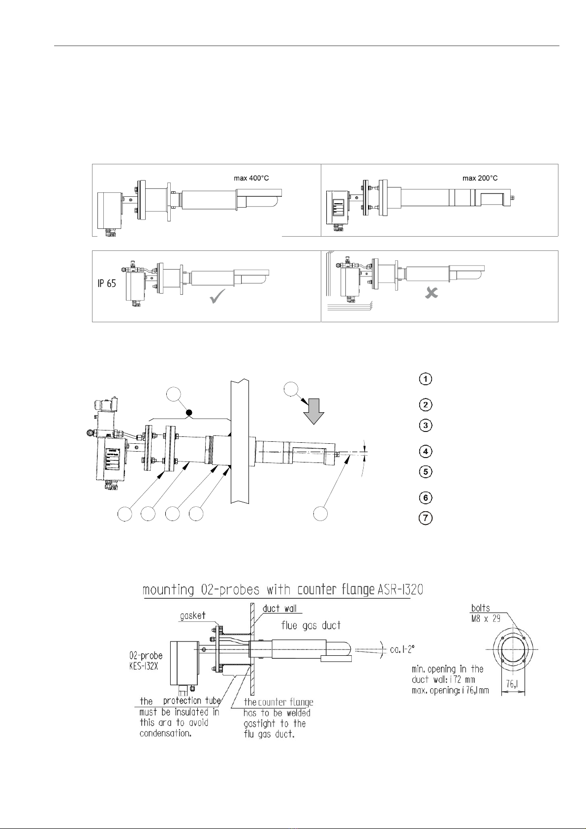
2.8 Mounting of the Probe
The mating flange must be
welded at the specified angle
Process gas flow
The welded seam must be gas-
tight
A
dapter (supplied by customer)
Stainless steel adapter with
R2½”-thread
A
QUATEC – Probe
Insulation
Figure 9 - Mounting the KES 132x with filter head KES-132060AK and adapter plate ASR-1320-KN
Figure 10 - Mounting of the O
2
probe KES-132x with ASR-1320
1-3°
1345
6
2
7
A
Q
U
A
T
E
C

Installation Installation and Operation Manual – AQUATEC 1000
14 Doc.-ID: AQUA_16012020_EN
2.9 Adjusting the V-shield / filter head
Before installing the probe, the direction of flue gas flow must be determined and the filter head assembly turned
to such a position that the V-shield faces the oncoming flue gas. The filter head can be turned freely a full 360° for
this purpose, by loosening the counter nut, loosening the Allen screw and rotating the filter head / V-shield to the
required position, and then tightening the Allen screw and counter nut.
Flue gas direction
V-shield (KES-132X/KES-200X)
V-shield ( KES500X)
Screws to secure filter head
Filter head
Rotation of filter head
Probe
Figure 11 - Adjustment of the V-shield
Loosen the locknut
Loosen the locknut
Adjust the filter head. Adjust the position of the
shield against the flow direction
Tighten the locknut
Tighten the locknut
Figure 12 - Adjustment the fitter head
1
2
3
4

Installation and Operation Manual – AQUATEC 1000 Installation
Doc.-ID: AQUA_16012020_EN 15
2.10 Electrical Connections of the Probe
Info
The probe cable (FEP-0001) has to be connected to the terminal board in the probe terminal box. Please do not
attach the shield to the probe.
1 : - mV O
2
sensor (white-brown)
2 : + mV O
2
sensor (brown)
3 : + mV thermocouple 1 (green)
4 : - mV thermocouple 1 (white)
6 : L 115VAC heater (black)
7 : N 115VAC heater (blue)
8 : PE Protection earth (green yellow)
9 : L 115VAC solenoid valve (grey)
10: N115VAC solenoid valve (grey-blue)
Figure 13 - Electrical Connections of the Probe
connections box
2.11 Requirements for Pneumatic Cable FEP-0002
Note the minimum bending radius.
FEP-0002R
min
= 138 mm
Temp. during installation
Temp. during operation
-
5 °C
Min.
+50 °C
Max.
-40 °C
Min.
+90 °C
Max.
Installation Installation and Operation Manual – AQUATEC 1000
16 Doc.-ID: AQUA_16012020_EN
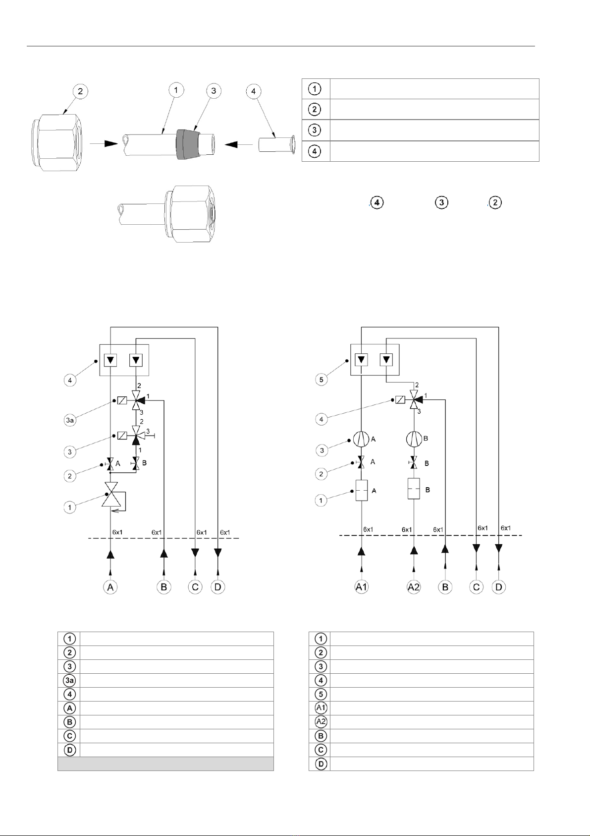
2.12 Preparation of the pneumatic Cable
Pneumatic tubing FEP-0002
Nut
Clamp ring
Support sleeve
Both, the pneumatic tubing for the reference air (blue)
and the test gas (green) have to be prepared with
support sleeves , clamp rings and nuts .
Figure 14 - Preparation of pneumatic tubes
2.13 Gas plans
Pneumatic version for Instrument air
SME-50000010 Pneumatic version with pumps
SME-50000020
Figure 15 - Gas plans
Pressure control valve Filter
Choke non return valve Choke non return valve
Solenoid valve 3/2 ways Reference air pump / Test air pump
Solenoid valve 3/2 ways Solenoid valve 3/2 ways
Flow meter Flow meter
Instrument air in, 4 – 10 Bar Reference air in
Test gas in, Max. 3 Bar Test air in
Test gas out, 150 - 180 l/h Test gas in
Reference air out, 30 – 40 l/h Test gas out, 150 - 180 l/h
Reference air out
Installation and Operation Manual – AQUATEC 1000 Installation
Doc.-ID: AQUA_16012020_EN 17
2.14 Pneumatic Connections of the Probe
Reference air in (FEP-0002: blue tube)
Test gas in ( FEP-0002: green tube)
Figure 16 - Pneumatic connections of the probe
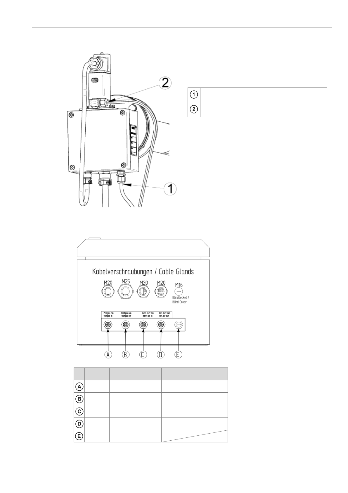
2.15 Pneumatic Connections of the Electronic Unit
Figure 17 - Bottom view of SME-53 with
integrated pneumatic unit
Nr. Tube Pump version Instrument air version
1/4“ Testgas in Testgas in
1/4“ Testgas out Testgas out
1/4“ Reference air input Instrument air in
1/4“ Reference air output Reference air out
1/4“ Test air input

Initial Operation Installation and Operation Manual – AQUATEC 1000
18 Doc.-ID: AQUA_16012020_EN
3 Initial Operation
3.1 Checklist before commissioning the system
Is the system number of the probe identical to the system number of the electronic unit? If not, change the
assignment.
Does the voltage specified on the name plate correspond to the line voltage? (See section 1.8 Name Plates)
If not, contact ENOTEC.
Is the electrical wiring connected correctly? (See section 2.6 AQUATEC 1000 Wiring Diagram)
Are the pneumatic connections correct and gas tight? (See sections 2.15 Pneumatic Connections)
Make sure that there are no leakages at the probe - e.g. is the counter flange welded gas tight to the duct and are the
flange bolts tightened sufficiently? Are gaskets in use? (See section 2.8 mounting of the Probe)
Do the conditions at site match the specification in the data sheets? (See section ATechnical Data)
Has the O2 reference value been entered into the system? (See section 3.9)
3.2 System Power Up
Switch on the line voltage to the system. After a short power up information, the user is prompted to
Select language, set the System date and System time.
The probe heating phase now begins which is followed by the measuring mode.
Figure 18 - System Power up. Note the software
version at the bottom right of the display.
3.3 Display - Probe Heating Phase
Figure 19 - O
2
sensor heating phase
The probe heating phase begins with the heating
up of the O
2
sensor.
Rising probe temperature
(or) waiting period
(or) heater error
Last access with corresponding date
Current temperature
A
nalogue temperature bar
Set point probe temperature
Softkey title: e.g. System menu
3.4 Display - Measuring Mode
Figure 20 - Measuring mode
Measured component
Measured value
A
ctive measuring range
Blinking indicators showing under or over
measuring range
A
nalogue bar showing measured value and
measuring range start and end
Softkey titles
Installation and Operation Manual – AQUATEC 1000 Initial Operation
Doc.-ID: AQUA_16012020_EN 19
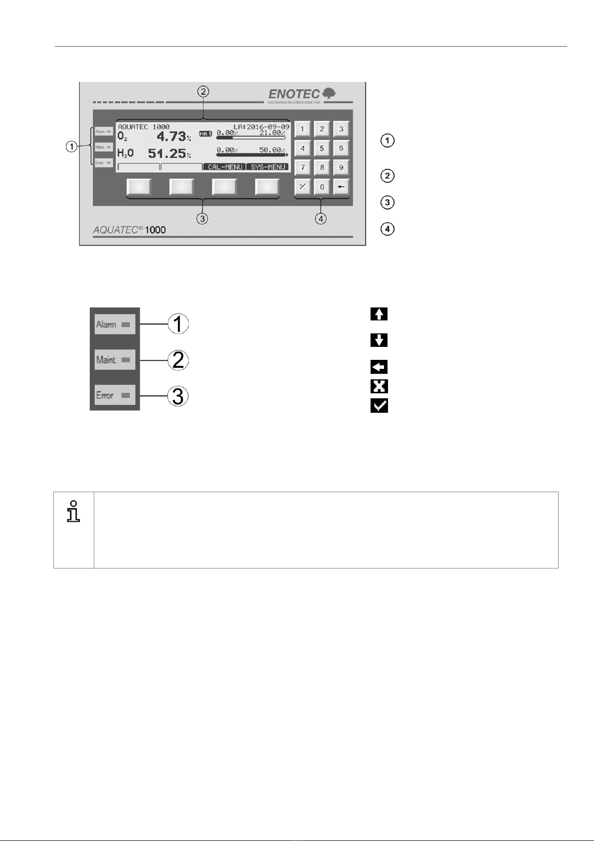
3.5 Keypad and Display
Figure 21 - Keypad and display
The controls and display of the AQUATEC
1000 are housed in the electronic unit and are
comprised of:
Three LED indicators depicting active
status
reports for limit alarms, maintenance and
system faults
Graphic enabled, back-lit display
Four softkeys with varying layout
(softkeys)
Numeric number bloc
3.6 Status LEDs 3.7 Softkey Symbols
Alarm, - orange - is lit when an
alarm has been activated (e.g.
O
2
limit alarm)
Moves the selection one position
upwards
Moves the selection one position
down-wards
Maint. - Orange - a function
has been accessed which may
affect the measurement
Leave an area
Abort a function or entry
Error - red - is lit when a
system error has occurred
Select or confirm a function/value
3.8 System Code
Info
The system code on delivery is 0000. In this state, entry into the system is granted without having to enter the
system code. The system code protects the system from unauthorized use. Functions which may alter the
measurement of O
2
are therefore also protected.
Caution: If the system code has been altered, it must be kept in a safe place!
3.9 Adjustment of the Analyzer to the Dryer
The water vapor is not measured directly, but is calculated using the measured oxygen content. The water vapor
concentration is proportional to the quantity of the displaced oxygen. The water vapor is calculated using the
measurement of the O
2
concentration.
The O
2
reference value (dry), which is necessary for this evaluation, is different for each dryer and process.
Before commissioning, the system must be adjusted to the dryer, of which moisture content is to be measured. This
is carried out under:
SYS MENU -> System configuration -> H2O measuring range -> O2 reference value (dry).
Software Overview and Explanations Installation and Operation Manual – AQUATEC 1000
20 Doc.-ID: AQUA_16012020_EN
4 Software Overview and Explanations
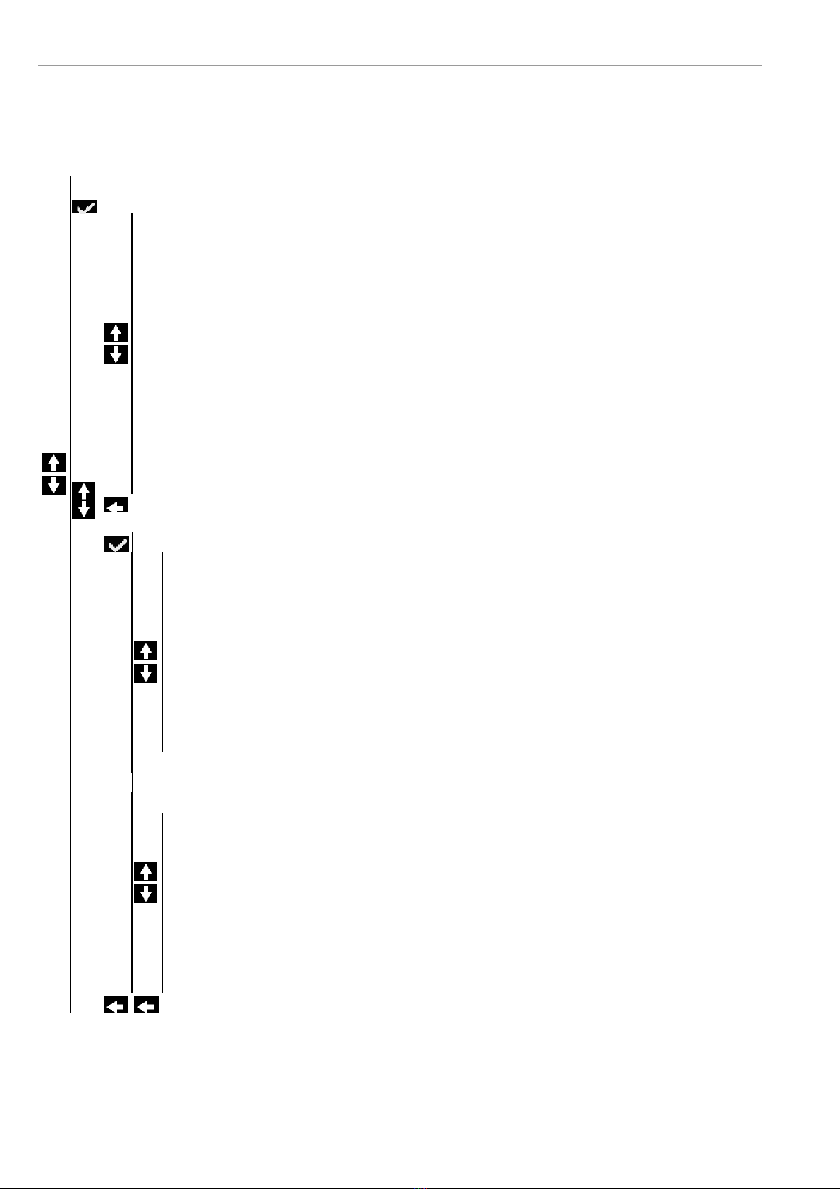
4.1 Menu Overview - SYS-MENU
SYS-MENU
System Information
Actual measured values
O2measured value (% O2) {may be ppm}
O2-mA output 17A/B (mA)
O2sensor input (mV)
H2O measured value
H2O mA output 34A/B
Flow rate reference air (l/h)
O2probe temperature (°C / °F)
O2probe heater power (%)
Thermocouple input (mV)
Terminal temperature (°C / °F)
Internal temperature (°C / °F)
Process pressure (rel) (mbar/psi)
O2 sensor life (%)
Lambda
Calibration results
e.g. 2012-05-11 (Choose date/time)
Executed at
Calibration method
O2 sensor calibration
~~ Calibration results ~~
O2value at test air (20,95 % O2)
♦calibrated to (% O2)
O2value at test gas (% O2) } only if determined
♦calibrated to (% O2)
~~ Calibration data ~~
O2sensor offset (mV)
O2sensor slope (mV / dec) } only 2 point calibration
~~ Test gas data ~~
Test air (20,95 % O2)
Test gas (e.g. 2,1 % O2)
~~ Sensor raw data~~
O2voltage at test air (mV)
♦at pressure (mbar/psi)
O2voltage at test gas (mV) } only if determined
♦at pressure (mbar/psi)
O2response to test gas (s) } only if determined
O2response to process (s) } only if determined
O2sensor life
Table of contents
Other Enotec Analytical Instrument manuals


