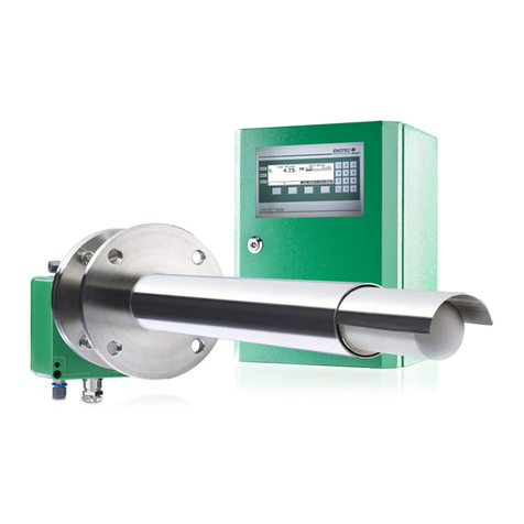
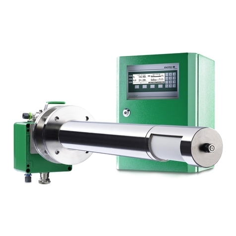
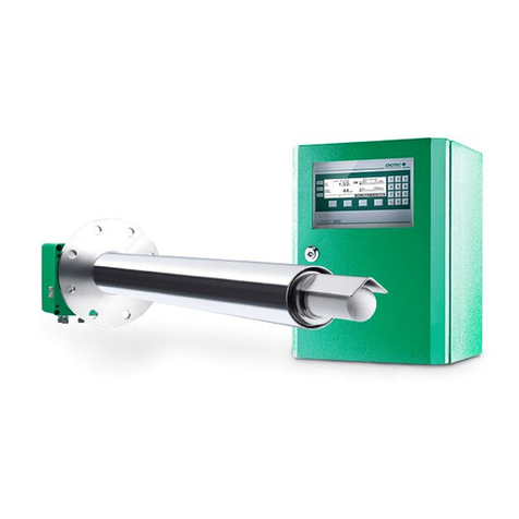
Enotec OXITEC ECONOMY User manual

Doc.-ID: ECO-12022015-EN
Installation and Operation Manual
O2 Analyzer System
OXITEC
®
ECONOMY
Version 1.10
for Software Version: 4.09

ENOTEC GmbH
Process and Environmental
Measuring Technology
DIN EN ISO 9001
Höher Birken 6
D-51709 Marienheide
Germany
Tel.: +49 (0) 2264 - 45 78 0
Fax: +49 (0) 2264 - 45 78 31
Internet: www.enotec.de
Preface
Dear Customer,
Thank you for selecting OXITEC ECONOMY as your InSitu Flue Gas Oxygen Analyzer System.
For more than 30 years now ENOTEC's Analyzer Systems have been operating in numerous applications with thousands of
units being produced and shipped around the world. ENOTEC is committed to absolute quality and performance and over time
we have continuously enhanced our products to integrate various features and functions. In this package, the electronic unit
uses the very latest Microprocessor Technology, making the SME5 electronic unit one of the most advanced and up-to-date
monitoring units, permitting you to reduce your maintenance & fuel costs, and to achieve increased measuring accuracy with
more operational reliability.
In all OXITEC measuring probes, the Zirconium Oxide Sensor is soldered in place using a special process and technique devel-
oped by ENOTEC. This technique results in a considerable increase in service life compared to „glued or cemented“ measuring
cells of ENOTEC competitors, which have a tendency to leak or crack during operation. The OXITEC sensor has a proven gas-
tight design, providing greater measuring accuracy, durability and longer working life time.
All ENOTEC instruments are thoroughly tested in the factory and are subject to a strict ISO9001 Quality Assurance Procedure.
Therefore, with the correct installation, the operation of the OXITEC ECONOMY is straightforward and user friendly and will
provide you with many years of trouble free operation with perfect measuring results.
Notes concerning this Manual
This manual contains important information concerning design, installation, commissioning, operation, maintenance and trou-
bleshooting of the OXITEC ECONOMY. Please familiarise yourself with all warnings, safety instructions and maintenance in-
structions included in this manual for a trouble-free and safe operation.
Symbols used in this Manual
The symbols below are found attached to the OXITEC® 5000 ECONOMY system and in this manual. They emphasize im-
portant information as well as safety instructions for installation, operation and maintenance, to protect the personnel and the
equipment.
Warning
Follow all instructions in this manual
Consider Information
Points out important information which must be
considered before execution
Warning hot Surface
Warns of danger of burns which could occur from
hot system parts
Info
Contains further detailed information
Attention
Warns of risks by destroying the system or its
components or its functionality
Ground earth electrical protection
The content of this manual, including all written content, images, drawings or any other content is protected by
copyright.
Safety Instruction
The OXITEC ECONOMY system is operated with line voltage. After removal of terminal covers some parts of this
system may be accessible which are under high line voltage.
Only well trained and authorised personnel are allowed to work on this system. The personnel must know and understand all
precautions, safety instructions, installation and maintenance instructions of this manual. The trouble free and safe operation
of OXITEC ECONOMY require safe transportation, professional storage, installation, operation and maintenance.
Furthermore all local safety requirements at the point of installation and operation must be considered.
OXITEC ECONOMY may not be used to measure oxygen in combustible gases or in an environment with combustible gases.
Parts of this system may cause an explosion risk.

Installation and Operation Manual – OXITEC Economy Table of Contents
Doc.-ID: ECO-12022015-EN 1
Table of Contents
1System Description 2
1.1System Overview ................................................2
1.2Intended Use of OXITEC ECONOMY .................3
1.3Disruption of the Process ....................................3
1.4Storage instructions ............................................3
1.5Name Plates .......................................................3
2Installation 4
2.1Installation Requirements for Electronic Unit ......4
2.1.1Access to the Terminals......................................5
2.2Installation of Probe Signal Cable .......................5
2.3Installation of the Probe ......................................6
2.4Install O2Probe ...................................................7
2.4.1Welding of the Counter Flange............................7
2.4.2Adjustment of the probe filter head .....................7
2.4.3Installation of the O2 Probe.................................8
2.4.4O2Probe installation with Cooling Protection Tube
............................................................................8
2.5Electrical Connections of the Electronic Unit.......9
2.6Electrical Wiring Diagram..................................10
2.6.1Relay Contacts, Functions ................................11
2.6.2Probe Connection .............................................11
3Initial operation 12
3.1Checklist before commissioning the system .....12
3.2System Power Up .............................................12
3.3Display - Probe Heating Phase .........................12
3.4Display - Measuring Mode ................................13
3.5Keypad and Display ..........................................13
3.6Status LEDs ......................................................13
3.7Softkey Symbols ...............................................13
3.8System Code.....................................................13
4Software Overview and Explanations 14
4.1Software Overview - SYS-MENU ...................... 14
4.2Software Explanations - SYS-MENU ................16
4.2.1O2Measuring Ranges (Scaling)........................16
4.2.2mA output on system errors..............................16
4.2.3O2limit alarm settings .......................................16
4.2.4O2Sensor calibration values.............................17
4.2.5Time per test gas apply.....................................17
4.2.6Delay time to process........................................17
4.2.7ENOTEC REMOTE...........................................17
4.2.8Measuring units.................................................18
4.2.9Language..........................................................18
4.2.10Change system code ........................................18
4.2.11Load factory settings.........................................18
4.2.12Service..............................................................18
4.3CAL MENU .......................................................19
4.3.1Check Test air / Test gas settings.....................19
4.3.2Calibration Menu - Display Overview................19
4.3.31-point calibration (manual)...............................20
4.3.42-point calibration (manual)...............................20
4.4System Check...................................................21
5Service and Maintenance 22
5.1Test Gas Tubing (Customer supply) ................. 22
5.1.1... preparation....................................................22
5.1.2... connecting ....................................................22
5.2Test Air Supply to the O2Probe ........................ 22
5.2.1…with Test Air Pump........................................22
5.2.2…with Test Gas Bottle......................................23
5.3Bottle Test Gas Supply to the O2 Probe ........... 23
5.4O2Probe Dismounting ...................................... 23
5.5Exchange the O2Probe Filter Head.................. 24
5.5.1Remove the Filter Head....................................24
5.5.2Remove the used Probe Filter..........................24
5.5.3Glue in New Probe Filter...................................24
6Status Messages 25
6.1Error Messages ................................................ 25
6.2Alarm Messages ............................................... 26
ATechnical Data 27
A.1Technical Specifications - Electronic Unit ......... 27
A.2Technical Specifications - Probe....................... 28
A.3Technical Specifications - Probe Cable ............ 28
BDimensional Drawings 29
B.1O2Probes ......................................................... 29
B.2Counter Flanges (Optional)............................... 30
B.3Dimensions of Electronic Unit ........................... 31
CSpare Parts 32
C.1O2Probe without Filter Head ............................ 32
C.2O2Probe Components...................................... 32
C.3Components of the Cooling Tube ..................... 33
C.4Electronic Unit................................................... 33
C.5Probe Cable with Plug ...................................... 35
DSystem Options 36
D.1O2Limit Alarms ................................................. 36
D.2Duct Flange ...................................................... 36
D.3Duct Flange Insulation ...................................... 36
D.4Cooling Tube Insulation .................................... 36
EEC Declaration of Conformity 37
FWarranty 38
Index 39

System Description Installation and Operation Manual – OXITEC Economy
2 Doc.-ID: ECO-12022015-EN
1 System Description
1.1 System Overview
Figure 1- OXITEC Economy System (for flue gas temperatures of up to 400°C)
Figure 2 - OXITEC Economy System (with cooling protection tube for flue gas temperatures of up to 1400°C)

Installation and Operation Manual – OXITEC Economy System Description
Doc.-ID: ECO-12022015-EN 3
1.2 Intended Use of OXITEC ECONOMY
Warning
The system cannot be used to determine the oxygen concentration of combustible gases or in a location where
combustible gases are present as the measuring cell temperature of 800°C could present an explosion hazard!
1.3 Disruption of the Process
The analyzer system has to be kept in operation also in the event of the process being disrupted or if the plant is
powered off temporarily (e.g. at night or during the weekend). Frequently cooling down and heating up of the probe
results in thermal stress of the hot probe parts (heater, thermocouple and sensor) and reduces their product life.
ENOTEC will not accept any responsibility for resultant damage.
1.4 Storage instructions
ENOTEC equipment and spares are to be stored in a dry and ventilated environment with temperatures between 5°C
and 35°C. Paint fumes, silicone sprays, etc. must be avoided in the storage environment.
1.5 Name Plates
Figure 3 - Name Plate Electronic Unit
Figure 4 - Name Plate O
2
Probe
The name plates contain year of manufacture, probe serial number, O
2
sensor number and system order
code . The system order code contains detailed system information which is detailed in the system test
report and is supplied with the system.

Installation Installation and Operation Manual – OXITEC Economy
4 Doc.-ID: ECO-12022015-EN
2 Installation
Warning
The device must be provided with an external power-off switch. The line voltage switch/fuse/breaker must be in
accordance with the local technical standards and should be near to the electronic unit and must be clearly marked as
such. The probe cable is suitable for an ambient temperature range from -40°C to +90°C. All other installed cables
must be suitable for the ambient temperature range at side and must have the required size. All electronic unit termi-
nals are specified from 0,08mm² (AWG 26) to 2,5mm² (AWG 14). If wire end ferrules are used the next smaller size is
required. Before removal of the electronic terminal cover the line voltage must be switched off. The line voltage to the
electronic unit must be switched on again after the cover is back in position. After installation power conducting parts
may not be accessible.
2.1 Installation Requirements for Electronic Unit
Keep the minimum distance to adjacent objects Install at eye level
Avoid vibrations greater than 2g Mind the IP code
Drilled holes for the electronic unit
Use suitable screws
Electronic unit
Figure 5 - Installation of the Electronic unit

Installation and Operation Manual – OXITEC Economy Installation
Doc.-ID: ECO-12022015-EN 5
2.1.1 Access to the Terminals
Figure 6 - Access to the terminals
2.2 Installation of Probe Signal Cable
Abide by the maximum cable length (max. 150m)
Cross the probe signal cable (FEP-0001) at right angle to power supply cables.
Note the minimum bending radius
Ambient temperatures
Temp. during installation
Temp. during operation

Installation Installation and Operation Manual – OXITEC Economy
6 Doc.-ID: ECO-12022015-EN
Figure 7 - Probe cable FEP-0001
Probe Cable FEP-0001
No. Function Diameter Colours Additional info.
Measuring cell 2 x 0,75 mm
2
white-brown / brown With shield
Thermocouple 2 x 0,75 mm
2
green / white With shield
Probe heating 3 x 1,5 mm
2
black / blue / green-
yellow
Solenoid valve 2 x 0,75mm
2
grey / grey-blue
Warning
The shielding of the probe cable FEP-0001 must be connected only to the electronic unit ground (PE) clamp. In no
case should the shield of the probe cable be also connected at the probe end.
2.3 Installation of the Probe
The ambient temperature at the connection box and
process temperatures may not be exceeded
Avoid vibrations greater 2g
Maintain the protection class of the connection box

Installation and Operation Manual – OXITEC Economy Installation
Doc.-ID: ECO-12022015-EN 7
2.4 Install O2Probe
2.4.1 Welding of the Counter Flange
Caution
The counter flange must be welded gas tight to the duct wall at the required angle.
Make sure that the combustion process is not in operation and the temperature of the flue gas duct at the mounting
place allows work without any risk of burns.
2.4.2 Adjustment of the probe filter head
Info
Please take note of the flue gas flow direction at the place of installation
Figure 9 - Filter head adjustment
Figure 8 - Welding of duct flange
Flue gas duct for the probe counter flange
The counter flange has to be welded with the
required negative angle.
Welding must be gas tight
Duct flange (optional from ENOTEC)

Installation Installation and Operation Manual – OXITEC Economy
8 Doc.-ID: ECO-12022015-EN
2.4.3 Installation of the O2 Probe
Caution
For probe installation into the duct flange use only new and undamaged gaskets .
Tighten the flange nuts correctly to get a gas tight flange connection. Insulate the duct flange to prevent
against dew point corrosion problems.
Do not leave the O
2
probe unheated inside of the duct for a period longer than 30 minutes.
Figure 10 - O
2
probe Installation
Duct Flange
Insulation of the duct flange
Probe flange gasket
Nut M12 with washer and spring
O
2
probe terminal socket
2.4.4 O2Probe installation with Cooling Protection Tube
Adjust the cooling
protection tube so
that the gas exit is
directed into the flue
gas flow direction.
Figure 11 - O
2
probe installation with cooling protection tube

Installation and Operation Manual – OXITEC Economy Installation
Doc.-ID: ECO-12022015-EN 9
2.5 Electrical Connections of the Electronic Unit
Figure 12 - Electrical connections of the electronic unit
Ferrite sleeves (ENOTEC supply) Analogue output cable (Customer)
Line voltage supply cable (Customer) Digital output cable (Customer)
O
2
Probe cable (already connected)
Line Voltage
1
O
2
Sensor Signal
1 L Phase 12 + brown
2 N Neutral Conductor 13 - Brown/white
3 PE Ground Earth thermocouple
Internal Power Supply (not in use) 14 + green
4 L 15 - white
5 N O
2
Analogue Output 4-20 mA
2
(active)
Shielding 17 A / B A + / B -
6 PE Relays contact Outputs
3
O
2
Probe heater 0-115V AC (controlled) 18 A / B Maintenance
8 L Black, phase 19 A / B System fault
9 N blue, neutral conductor 21 A / B O
2
Limit alarm 1
4
10 PE green/yellow, protective earth conductor 22 A / B O
2
Limit alarm 2
5
1
Line voltage, frequency and rated current, see electronic name plate
2
Isolated mA output, Burden see technical data electronic unit
3
Voltage and current limits see technical data electronic unit
4
Option
5
In certain applications, it is possible that the contact function is inverted

Installation Installation and Operation Manual – OXITEC Economy
10 Doc.-ID: ECO-12022015-EN
2.6 Electrical Wiring Diagram
Figure 13 - Electrical wiring diagram

Installation and Operation Manual – OXITEC Economy Installation
Doc.-ID: ECO-12022015-EN 11
2.6.1 Relay Contacts, Functions
Relay Contact for Contact closed Contact open
System fault No System fault System fault has occurred (error code on display)
Maintenance System switched off or Maintenance
active
No maintenance
O
2
Limit alarm 1 (optional) O
2
Limit alarm 1 not active System switched off or O
2
Limit alarm 1 active
O
2
Limit alarm 2 (optional) O
2
Limit alarm 2 not active System switched off or O
2
Limit alarm 2 active
2.6.2 Probe Connection
O
2
Probe plug has to be
inserted into the probe socket and
locked with the retaining clip .
Figure 14 - Probe connection

Initial operation Installation and Operation Manual – OXITEC Economy
12 Doc.-ID: ECO-12022015-EN
3 Initial operation
3.1 Checklist before commissioning the system
Is the system number of the probe identical to the system number of the electronic unit? If not, change the
assignment.
Does the voltage specified on the name plate correspond to the line voltage? (See section 1.5 - Name Plates)
If not, contact ENOTEC.
Is the electrical wiring connected correctly? (See section 2.6 - Wiring Diagram)
Make sure that there are no leakages at the probe - e.g. is the counter flange welded gas tight to the duct and are
the flange bolts tightened sufficiently? Are gaskets in use? (See section 2.4 – Install O2 Probe)
Do the conditions at site match the specification in the data sheets? (See section A- Technical Data)
3.2 System Power Up
Switch on the line voltage to the system. After a short power up information, the user is prompted to
Select language, set the System date, System time, enter a TAG number and ENOTEC REMOTE code (only if
option ENOTEC REMOTE is factory activated).
The probe heating phase now begins which is followed by the measuring mode.
Figure 15 - System Power up. Note the software
version at the bottom right of the display.
3.3 Display - Probe Heating Phase
Figure 16 - O
2
sensor heating phase
The probe heating phase begins with the heating
up of the O
2
sensor.
TAG number
Analogue temperature bar
Last access with corresponding date
Rising probe temperature
(or) waiting period
(or) heater error
Current temperature
Softkey title: e.g. System menu

Installation and Operation Manual – OXITEC Economy Initial operation
Doc.-ID: ECO-12022015-EN 13
3.4 Display - Measuring Mode
TAG number
Measured value
Blinking indicators showing under or over
measuring range
Last access
Measured component
Softkey titles
Figure 17 - Measuring mode
3.5 Keypad and Display
Figure 18 - Keypad and display
The controls and display of the
COMTEC® 6000 are housed in the
electronic unit and are
comprised of:
Three LED indicators depicting
active status
reports for limit alarms, mainte-
nance and system faults
Graphic enabled, back-lit dis-
play
Four softkeys with varying lay-
out
(softkeys)
Numeric number bloc
3.6 Status LEDs 3.7 Softkey Symbols
Alarm, - orange - is lit when an
alarm has been activated (e.g.
O
2
limit alarm)
Moves the selection one position upwards
Moves the selection one position down-
wards
Maint. - Orange - a function has
been accessed which may
affect the measurement
Leave an area
Abort a function or entry
Error - red - is lit when a system
error has occurred
Select or confirm a function/value
3.8 System Code
Info
The system code on delivery is 0000. In this state, entry into the system is granted without having to enter the
system code. The system code protects the system from unauthorised use. Functions which may alter the
measurements are therefore also protected.

Software Overview and Explanations Installation and Operation Manual – OXITEC Economy
14 Doc.-ID: ECO-12022015-EN
4 Software Overview and Explanations
4.1 Software Overview - SYS-MENU
SYS-MENU
System Information
Actual measured values
O2measured value (% O2)
O2-mA output 17A/B (mA)
O2sensor input (mV)
O2probe temperature (°C / °F)
O2probe heater power (%)
Thermocouple input (mV)
Terminal temperature (°C / °F)
Internal temperature (°C / °F)
O2 sensor life (%)
Calibration results
e.g. 2011-01-31 (Choose date/time)
Executed at
Calibration method
O2 sensor calibration
~~ Calibration results ~~
O2value at test air (20,95 % O2)
♦calibrated to (% O2)
O2value at test gas (% O2) } only if determined
♦calibrated to (% O2)
~~ Calibration data ~~
O2sensor offset (mV)
O2sensor slope (mV / dec) } only 2 point calibration
~~ Test gas data ~~
Test air (20,95 % O2)
Test gas (e.g. 2,1 % O2)
~~ Sensor raw data~~
O2voltage at test air (mV)
O2voltage at test gas (mV) } only if determined
O2response to test gas (s) } only if determined
O2response to process (s) } only if determined
O2sensor life
Device operating data
Powers on counter
Hours in operation
Min. internal temperature
Max. internal temperature
Software version and options
Software OXITEC 5000 ECONOMY
~~ Options ~~

Installation and Operation Manual – OXITEC Economy Software Overview and Explanations
Doc.-ID: ECO-12022015-EN 15
♦.....
SYS-MENU
System configuration
O2Measuring ranges
Meas.range from (% O2)
Meas.range to (% O2)
mA output type (0-20 mA / 4-20 mA)
mA output on system error (mA)
O2sensor calibration values
O2cal.value - offset (mV)
O2cal.value - slope (mV/dec)
Calibration settings
Time per test gas apply (Min.)
Delay time to process (Min.)
ENOTEC REMOTE settings (optional)
ENOTEC REMOTE (ON/OFF)
Passkey (8 digit code)
Range (Short / Medium / Maximum)
System clock/TAG number
System date (jjjj-mm-tt)
System time (hh:mm:ss)
Measuring units
Temperature (°C / °F)
Language
Choose language (Deutsch / English / Spanish / Polish)
Change system code
Load factory settings
Service

Software Overview and Explanations Installation and Operation Manual – OXITEC Economy
16 Doc.-ID: ECO-12022015-EN
4.2 Software Explanations - SYS-MENU
4.2.1 O2Measuring Ranges (Scaling)
Figure 19 - O
2
Measuring Ranges
The O
2
Measuring range is linearly scaled and converted to a
linear current output (0/ 4-20 mA).
The parameter „O
2
Measuring range from“ is the start value of the
O
2
range, leading to an analogue output of 4,00 mA.
„O
2
measuring range to“ is the end value of the O
2
range, leading
to an output of 20,00 mA.
If a measured value is lower than the start value of the O
2
measuring
range, the current output signal drops to 3,60 mA.
(If the current output is set to 0- 20 mA the output is 0 mA)
If the measured O
2
value is higher than the end value of the O
2
measuring range end, the analogue output rises to 20,40 mA.
If during normal operation the measured O
2
value is under, or over
the programmed measuring range, an error message appears on
the display (in measuring mode).
4.2.2 mA output on system errors
Here the mA output value is set corresponding to a measurement error. The measurement output range for the
shown value (3,60 mA .... 20,40 mA) cannot be defined in this case.
4.2.3 O2limit alarm settings
Figure 20 - O
2
limit alarm settings
The entry "by" sets the value at which the O
2
limit alarm is activated.
The O
2
limit alarm function "min" defines a value by which the
limit alarm is activated if the measured O
2
value falls below the
set limit.
If the hysteresis is set to greater than 0,00,
the limit alarm is reset when the measured O
2
value rises above the
set O
2
limit plus the hysteresis value .
The O
2
limit alarm function "max" defines a value by which the
limit alarm is activated if the measured O
2
value rises above the
limit.
If the hysteresis is set to greater than 0,00,
the limit alarm is reset when the measured O
2
value falls below the
O
2
limit minus the hysteresis value.
If the hysteresis is set to 0,00 % O
2
, the triggered limit alarm must be
manually reset.

Installation and Operation Manual – OXITEC Economy Software Overview and Explanations
Doc.-ID: ECO-12022015-EN 17
4.2.4 O2Sensor calibration values
Info
The sensor calibration values can be altered through a 1 or 2 point calibration. Manual entry of values is only
necessary after replacing the O
2
sensor.
4.2.5 Time per test gas apply
Here the maximum duration of time for the application of test gas or test air is set. If sensor stability is not reached
within the maximum time, the following error message is displayed: “O
2
Sensor calibration failed - O
2
sensor
signal instable” This problem can be offset by setting a longer duration. The factory setting for maximal duration is
10 Minutes. If necessary, the time can be adjusted between 5 minutes and 30 minutes.
4.2.6 Delay time to process
Here the delay time showing the last measured O
2
value from the data storage is frozen after test air or test gas has
been applied (only when "Meas. value hold on cal. is set to on) This value also sets the time for showing the trend
representation on the display after test air or test gas application after a sensor calibration is set.
4.2.7 ENOTEC REMOTE
Info
If ENOTEC REMOTE is set to "OFF", password and range are not displayed.
The ENOTEC REMOTE password is used for:
authentification and pairing with a smartphone / tablet / laptop / pc.
authentification / login after every connection. Without Authentication / login, device data cannot be read or
modified. The device configuration can also not be altered.
Range limits the transmission power of the ENOTEC REMOTE module. Maximum = 100m, medium = 10m, short =
1m. The actual possible range may vary due to structural factors and the reception strength of the strength of the
Smartphone/Tablet.
When an ENOTEC REMOTE connection to the
analyzer is active, the connection is shown in the
upper right corner of the display .
Figure 21 - ENOTEC REMOTE connection active
Info
A maximum of 16 users (smartphones /tablets) can connect to the ENOTEC REMOTE module of an ENOTEC
analyzer. Should additional users attempt a connection, the connection will fail. In this case, manually switch off the
ENOTEC REMOTE and switch it back on again SYS MENU => System configuration => ENOTEC REMOTE Set-
tings which will reset the module.All previously paired users will need to delete their saved connection to the ana-
lyzer and re-pair their devices.

Software Overview and Explanations Installation and Operation Manual – OXITEC Economy
18 Doc.-ID: ECO-12022015-EN
4.2.8 Measuring units
Measuring units can be set for temperature (°C / °F).
4.2.9 Language
Set the language for all text shown on the display. One can choose between English, German, Spanish and Polish.
4.2.10 Change system code
Info
The system code on delivery is 0000. In this state, entry into the system is granted without entering the
system code. For security reasons, change the code and store it in safety. In case of loss of the system
code, a system reset has to be carried out. The reset process may only be carried out by trained service
technicians. As an option, a 6 digit code is available.
4.2.11 Load factory settings
Loading factory settings will restore all original settings and values to the default values programmed in the factory. If
activated, all set parameters and also values such as sensor calibration values and calibration results are lost. Take
note of the sensor calibration values beforehand and re-enter them after the loading the factory settings. If this is not
done, a calibration has to be carried out.
4.2.12 Service
The service functions are password protected and are only accessible by trained service personnel. These functions
are protected with a code, different to the system code.
Table of contents
Other Enotec Analytical Instrument manuals
