Enotec COMTEC 6000 User manual
Doc.-ID: COM6000_11022020_EN
Installation and Operation Manual
O
2
/ COe Analyzer System
COMTEC
®
6000
Version 18
for software version: 4.13
Doc.-ID: COM6000_11022020_EN
Preface
Dear Customer,
Thank you for selecting the COMTEC
®
6000 as your InSitu Flue Gas Oxygen/Combustibles (CO
e
) measuring system.
Since 1980 our analyzer systems have been operating in numerous applications with tens of thousands of units being produced
and shipped worldwide. ENOTEC is committed to absolute quality and performance and over time we have continuously en-
hanced our products to integrate various features and functions.
In this package, the electronic unit uses the very latest Microprocessor Technology, making the SME5 electronic unit one of the
most advanced and up-to-date monitoring units, permitting you to reduce your maintenance & fuel costs and to achieve in-
creased measuring accuracy with operational reliability.
The COMTEC
®
6000 is a unique O
2
und CO
e
analyzer system for reliable InSitu measurement and analysis in flue and process
gases which enables a redundant measurement of Oxygen and combustibles with high accuracy. The installed MXP sensor
measures not only CO but also all other combustibles (hydrocarbons and hydrogen) present. This one of a kind analyzer system
is the ideal flue gas analyzer for all fuels such as coal, oil, gas and also waste products of all kinds.
All ENOTEC instruments are thoroughly tested in the factory and are subject to a strict ISO9001 Quality Assurance Procedure.
Therefore, with the correct installation, the operation of the COMTEC
®
6000 is straightforward and user friendly and will
provide you with many years of trouble free operation with perfect measuring results.
Symbols used in this Manual
The symbols below are found attached to the COMTEC® 6000 system and in this manual. They emphasize important
information as well as safety instructions for installation, operation and maintenance, to protect the personnel and the
equipment.
Warning
Follow all instructions of this manual
Consider Information
Points out important information which must be
considered before execution
Warning hot Surface
Warns of danger of burns which could occur from
hot system parts
Note
Contains further detailed information
Caution
Warns of risks of destroying the system or its
components or its functionality
Ground earth electrical protection
The contents of this manual are protected by copyright. Alterations and errors reserved.
Safety Instructions
This system is operated with line voltage. If covers are removed during which line voltage is still connected, an electric shock
hazard will occur.
Only well trained and authorized personnel are allowed to conduct work on this system. Personnel have to understand all
precautions, safety instructions, installation and maintenance instructions in this manual. The trouble free and safe operation of
this system requires safe transportation, professional storage, installation, operation and maintenance.
Furthermore, all local safety requirements have to be considered.
This system may not be used in the vicinity of combustible gases as parts of the system may cause a risk of explosion.
The device may only be put into operation if the enclosed instructions have been fully understood.
This manual is also available in other languages on request.

Installation and Operation Manual OXITEC®5000 Table of Contents
Doc.-ID: COM6000_11022020_EN 3
Table of Contents
1System Description 4
1.1System Overview of the COMTEC 6000.............4
1.2Measuring Principles...........................................6
1.3Intended Use of COMTEC 6000 .........................6
1.4Safety Hazards....................................................7
1.5Disruption of the Process ....................................7
1.6Storage instructions ............................................7
1.7Name Plates .......................................................8
2Installation 9
2.1Installation requirements for electronic unit.........9
2.2Installation of probe signal cable FEP-0007/8...10
2.3Access to the Terminals....................................11
2.4Ferrite Sleeves (EMC).......................................11
2.5Wiring diagram of the Electronic Unit ................12
2.6Wiring Diagram of the COMTEC 6000 System .13
2.7Installation of the probe.....................................14
2.8Mounting of the Counter Flange at the Duct .....14
2.9Adjustment of the Probe Filter Head .................15
2.10Probe Protection Tube at the Mounting Flange.15
2.11Insulating the Protection Tube outside the Duct 16
2.12Electrical Connections of the Probe ..................17
2.13Requirements for Pneumatic Cable FEP-0002 .17
2.14Preparation of the pneumatic Cable..................18
2.15Pneumatic Connections of the Probe................18
2.16Pneumatic Connections of Electronic Units ......19
3Initial Operation 20
3.1Checklist before commissioning the system .....20
3.2System Power Up .............................................20
3.3Display - Probe Heating Phase .........................20
3.4Display - Measuring Mode ................................21
3.5Keypad and Display ..........................................21
3.6Status LEDs ......................................................21
3.7Softkey Symbols ...............................................21
3.8System Code.....................................................21
4Software Overview and Explanations 22
4.1Software Overview - SYS-MENU ...................... 22
4.2Software Explanations - SYS-MENU ................26
4.2.1O2Measuring Ranges (Scaling)........................26
4.2.2Limit alarm settings ...........................................26
4.2.3O2Sensor calibration values ............................. 26
4.2.4Measuring value averaging for (O2/ COe).........26
4.2.5mA output on system errors (O2and COe) ........ 27
4.2.6COeMeasuring Ranges (Scaling) .....................27
4.2.7COeSensor Calibration values..........................27
4.2.8Time per test gas apply.....................................27
4.2.9Delay time to process........................................27
4.2.10Pre-purge time ..................................................27
4.2.11Automatic Calibration (ACAL) ...........................28
4.2.12ENOTEC REMOTE...........................................29
4.2.13Measuring units.................................................29
4.2.14Language ..........................................................29
4.2.15Change system code ........................................29
4.2.16Load factory settings .........................................30
4.2.17Set COemeasurement to off/on ........................30
4.2.18Service.............................................................. 30
4.3System Checks................................................. 31
4.4CAL MENU ....................................................... 31
4.4.1Calibration Menu - Display Overview ................ 32
4.4.21-point calibration (O2and/or COe) (manual) .... 33
4.4.32-point calibration (O2and/or COe) (manual) .... 33
5Service and Maintenance 34
5.1Exchange fuses ................................................ 34
5.2Pressure and Flow rates for Test Air and/or
Reference Air.................................................... 35
5.3Adjusting Flow Rate (SME 53 with Pneumatics)35
5.4Position of the adjustment valves ..................... 36
5.5Adjusting Flow Rate (SME-54).......................... 36
5.6Replacing the Filter ........................................... 37
5.7Replacing the probe.......................................... 38
5.8Exchange of Probe Inner Part........................... 39
5.9Replacing the O2Sensor .................................. 40
5.10Replacing the COeSensor................................ 41
5.10.1Seal the COesensor guide tube........................ 42
5.11Relay Outputs / Functions and Correlation ....... 43
6Status Messages 44
6.1Error Messages ................................................ 44
6.2Alarm Messages ............................................... 46
6.3Service Messages ............................................ 46
7Troubleshooting 47
ATechnical Data 49
A.1Technical Specifications - Electronic Unit ......... 49
A.2Technical Specifications - Probes ..................... 50
Requirements of the Gas Supply .................................... 51
BDimensional drawings 52
B.1Electronic Units................................................. 52
B.2Dimensional drawing of probes KES600x......... 53
B.3Counter flanges ................................................ 54
B.4Dimension of Protection Tube Flanges ............. 55
B.5Probe components............................................ 56
B.6Probe inner parts assembly .............................. 57
B.7Gas plans.......................................................... 58
CSpare Parts 61
C.1Mounting Plates of SME-53 Electronic Unit ...... 61
C.2Mounting Plates of 19" Rack SME-57............... 63
C.3Display Board ................................................... 64
DWarranty 65
EDeclaration of Conformity 66
Index 67
System Description Installation and Operation Manual - COMTEC
®
6000
4 Doc.-ID: COM6000_11022020_EN
1 System Description
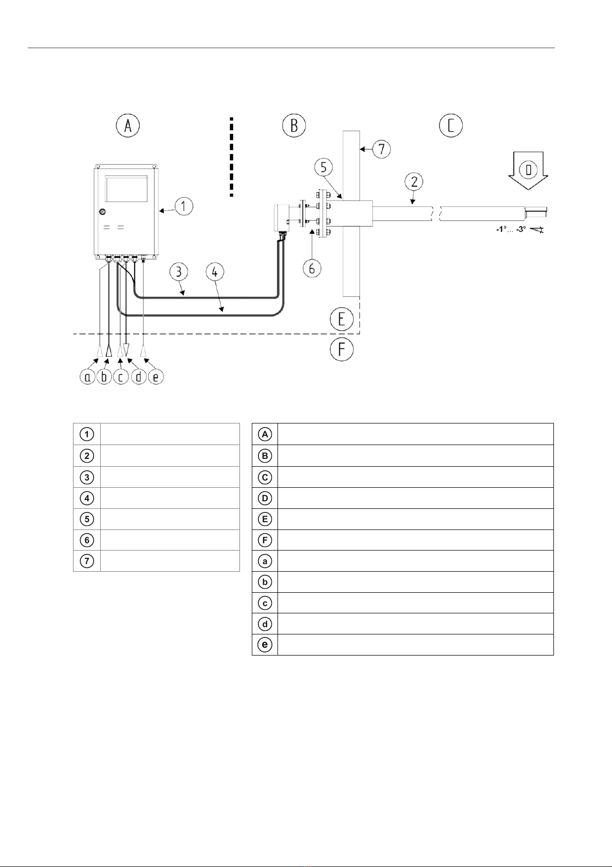
1.1 System Overview of the COMTEC 6000
Figure 1 - System overview of the COMTEC 6000 for flue gas temperatures of up to 600° C
Electronic unit SME5 / IP66
Safe Area - Max. ambient temp.: -20 °C to +55 °C
(-4 °F to + 131 °F)
InSitu measuring probe / IP65
Safe Area - Max. ambient temp.: -40°C to +80°C
(-4 °F to + 167 °F)
Pneumatic cable Duct / combustion chamber
O
2
probe signal cable Flue gas direction – max. flue gas temperature 500 °C
Counter flange Manufacturer supply
Isolation: Customer Customer supply
Duct wall Test gas in
Power supply
Instrument air in
Output signals (analog and digital)
Test air in (only with pump version of electronics)
Installation and Operation Manual - COMTEC
®
6000 System Description
Doc.-ID: COM6000_11022020_EN 5
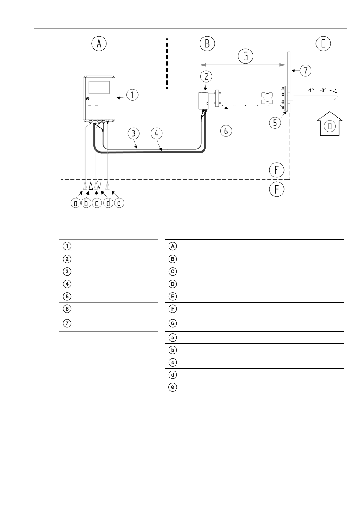
Figure 2 - System overview of the COMTEC 6000 with cooling protection tube for flue gas temperatures of up to
1400° C
Elektronik SME5 / IP66
Safe Area - Max. ambient temp.:-20 °C to +55 °C
(-4 °F to + 131 °F)
InSitu measuring probe / IP65
Safe Area - Max. ambient temp.:-40 °C to +80 °C
(-4 °F to + 167 °F)
Pneumatic cable Duct / combustion chamber
O
2
probe signal cable Flue gas direction – max. flue gas temperature 1600 °C
Counter flange Manufacturer supply
Isolation: Customer Customer supply
Duct wall
Space required: 2.0 m for standard installation.
0.8 m for 90° elbow construction
Test gas in
Power supply
Instrument air in
Output signals (analog and digital)
Test air in (only with pump version of electronics)

System Description Installation and Operation Manual - COMTEC
®
6000
6 Doc.-ID: COM6000_11022020_EN
1.2 Measuring Principles
The COMTEC
®
6000 O
2
/ CO
e
analyzer system consists of an in-situ probe which is installed in a duct to measure
non-combustible process gases and of an electronic unit for voltage and gas supply, as well as for signal processing.
The O
2
sensor of the COMTEC 6000 is at the tip of the probe and is regulated to 800 °C and works on the zirconium
oxide principle of measurement. Here, a mV signal between the reference gas side of the sensor (inside, instrument
air 20.95% O
2
) and the measured gas side is measured, which depends logarithmically on the ratio of oxygen partial
pressures on both sides of the sensor. The mV signal is converted according to the Nernst equation into oxygen par-
tial pressure within the process gas, whereby the O
2
concentration is determined in the process gas. Gas-tight sepa-
ration of reference air and process gas is of particular importance.
The CO
e
sensor at the tip of the COMTEC
®
6000 probe detects combustible, gaseous molecules whereby the meas-
ured value corresponds to the CO equivalent (CO
e
= CO equivalent). This value can be used as an indication of the
combustion efficiency. A high CO
e
value correlates with poor efficiency because a portion of the fuel is not completely
oxidized.
The InSitu sensor is in contact with the sample gas with both electrodes. These catalytically active electrodes cause
oxidation of the non-oxidized gas molecules, so that a voltage is generated between the electrodes, which depend on
the CO
e
concentration. Thus CO, H2 and C
x
H
y
(Hydrocarbons) can be measured.
1.3 Intended Use of COMTEC 6000
Info
ENOTEC InSitu analyers measure in flue gases of combustion plants or in comparable inert gas
mixtures. If oxidizable gas components are contained in these processes, contact ENOTEC..
Info
The COMTEC 6000 InSitu Analyzer System is a system for measuring the oxygen concentration and
the concentration of CO
e
in flue gases. For reasons of safety and the possible occurrence of accidents,
unauthorized conversions and modifications of the system are prohibited.
Warning
The COMTEC 6000 analyzer system may not be used to determine the oxygen content in combustible
gases or be used in the vicinity of combustible gases. Doing this will cause a risk of explosion.
Info
The minimum concentration of O
2
in flue gas should, under normal process conditions, not be less than
0.5%.
If a reducing atmosphere of less than 0,5% O
2
regularly occurs, ENOTEC recommends CSP (Cell Surface
Protection) for lasting protection of the measuring cell. (CSP is optional)
Info
The CO
e
sensor requires a minimum O
2
concentration for correct measurement.
If the O
2
concentration falls below this limit, the CO
e
measured value as well as the mA output rises up to
the highest possible value for the given measuring range.
Caution
Under no circumstance should the measuring probe be directly connected to the 230V main power sup-
ply, as this will immediately destroy the probe heater element!

Installation and Operation Manual - COMTEC
®
6000 System Description
Doc.-ID: COM6000_11022020_EN 7
1.4 Safety Hazards
Warning hot Surface
During operation, the temperature of the probe filter head and of all parts exposed to flue gas is 150 °C –
600 °C (302 °F-932 °F). Direct contact with the hot parts for dismantling or maintenance will cause se-
vere burns!
The probe may only be removed with heat-insulated gloves. Before removing the probe, always switch off
the supply voltage to the electronic system. After removal, store the probe in a safe, protected place and
wait until it has cooled downs below 35 °C (95 °F).
1.5 Disruption of the Process
The analyzer system has to be kept in operation also in the event of the process being disrupted or if the plant is
powered off temporarily (e.g. at night or during the weekend). Frequently cooling down and heating up of the probe
results in thermal stress of the hot probe parts (heater, thermocouple and sensor) and reduces their product life.
ENOTEC will not accept any responsibility for resultant damage.
1.6 Storage instructions
ENOTEC equipment and spares are to be stored in a dry and ventilated environment at temperatures between
-40 °C to +80 °C (-40 °F to 176 °F). Paint fumes, silicone sprays, etc. must be avoided in the storage environment.
System Description Installation and Operation Manual - COMTEC
®
6000
8 Doc.-ID: COM6000_11022020_EN
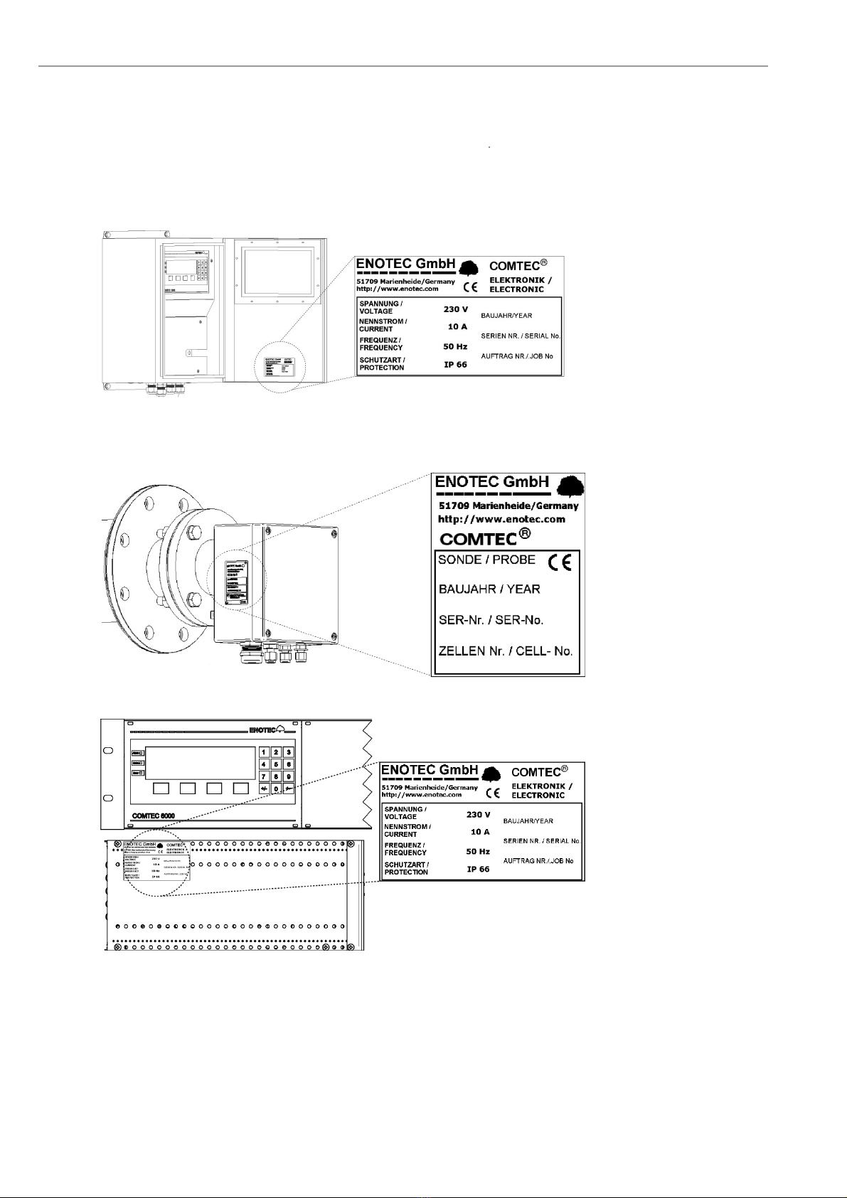
1.7 Name Plates
The name plate contains information about the line voltage, the nominated current, frequency, protection class, year
of manufacture, serial number, order number and system order code.
The system order code refers to information which is detailed in the system test report and supplied with the system.
SME-53
Probe Connection
Box
SME-57
(19" rack)
Figure 3 - Name Plates
Installation and Operation Manual - COMTEC
®
6000 Installation
Doc.-ID: COM6000_11022020_EN 9
2 Installation
Warning
The electronic unit does not have a line voltage main switch. The line voltage power supply requires a
switch or breaker. The line voltage switch/fuse/breaker must be in accordance with the local technical
standards and should be in close proximity to the electronic unit and must be identifiable as such.
The probe cable is suitable for an ambient temperature range from -40°C to +90°C. All other installed
cables must be suitable for the ambient temperature range at side and must have the required size. All
electronic unit terminals are specified from 0,08mm² (AWG 26) to 2,5mm² (AWG 14). If wire end ferrules
are used the next smaller size is required. Before removal of the electronic terminal cover the line voltage
must be switched off. The line voltage to the electronic unit must be switched on again after the cover is
back in position. After installation, power conducting parts may not be accessible.
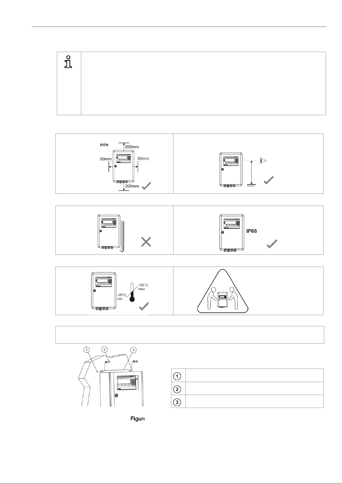
2.1 Installation requirements for electronic unit
Keep the minimum distance to adjacent objects
Install at eye level
Avoid vibrations greater than 2g
Mind the IP code
Heavy equipment, ensure
proper lifting and carrying
Ambient temperatures
Min.: -20 °C (-4 °F) / Max.: +55 °C (+131 °F) - (Pump version 20°C - +50°C)
Drilled holes for the electronic unit
Use suitable screws
Electronic unit
Figure 4 - Installation of the Electronic unit
Installation Installation and Operation Manual - COMTEC
®
6000
10 Doc.-ID: COM6000_11022020_EN
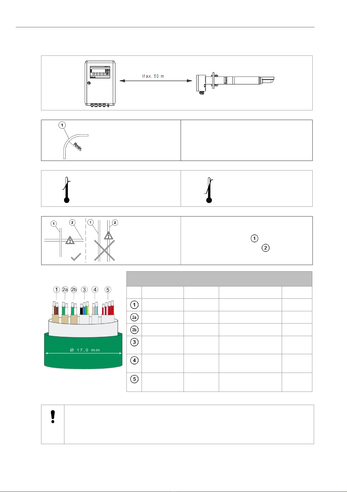
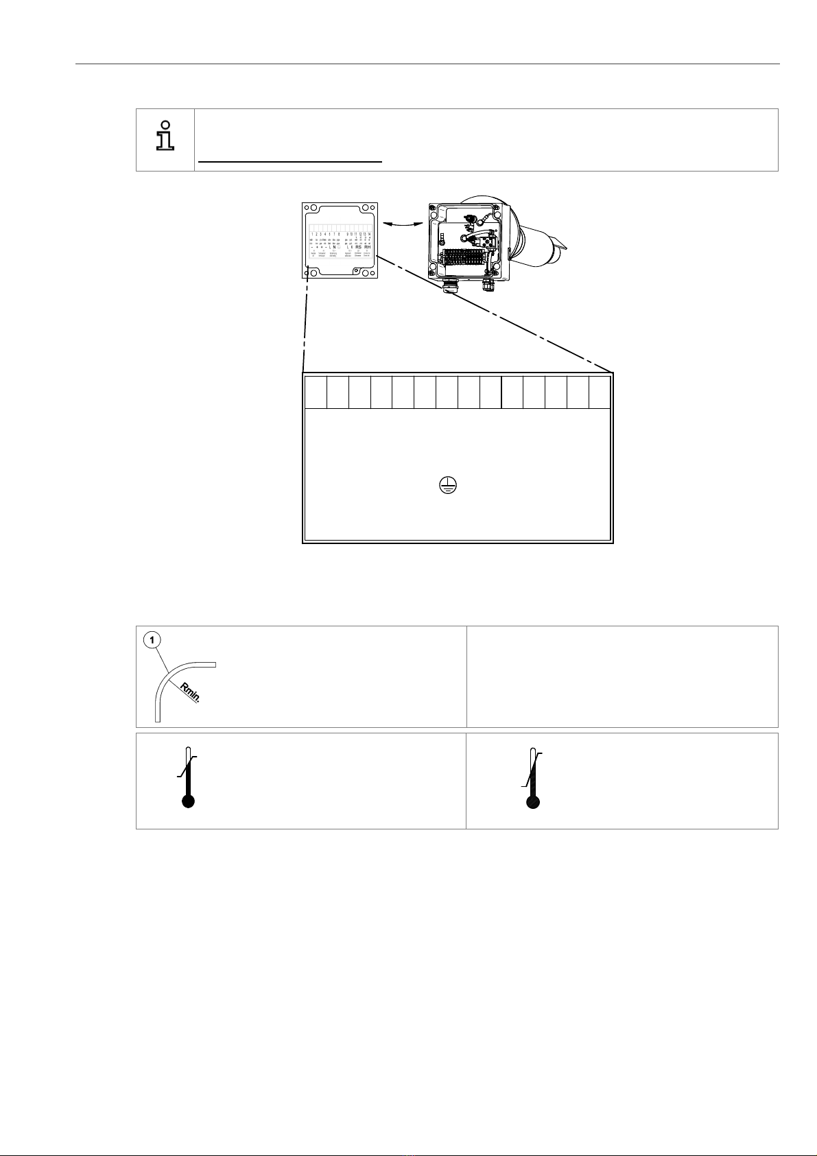
2.2 Installation of probe signal cable FEP-0007/8
Abide by the maximum cable length (max. 50m)
Note the minimum bending radius.
FEP-0007Rmin=252 mm
FEP-0008Rmin=329 mm
Temperature during installa-
tion Temperature during operation
Cross the probe signal cable (FEP-0007/8) at right
angle to any power supply cables .
COMTEC Probe Cable FEP-0007 (FEP-0008 armored)
No. Function Diameter Colors Info.
Measuring cell 2 x 0,75 mm
2
white-brown / brown With shield
Thermocouple 1 2 x 0,75 mm
2
green / white With shield
Thermocouple 2 2 x 0,75 mm
2
green / white With shield
Probe heater 3 x 1,5 mm
2
black / blue / green-
yellow
Probe Solenoid
valve 2 x 0,75mm
2
grey / grey-blue
CO
e
Sensor
heater and
il
4 x 1,0mm
2
red-white / red-white /
red / red
Figure 5 - Probe cable FEP-0007
Caution
Only use ENOTEC probe cables, as the thermocouple cables 2a and 2b are compensating cables and
are necessary for correct measurement.
The shield of the probe cable must only be connected at the electronic housing at the PE terminal. Under
no circumstance should the shield also be connected at the probe.
-
5 °C
Min.
+50 °C
Max.
-40 °C
Min.
+90 °C
Max.
Installation and Operation Manual - COMTEC
®
6000 Installation
Doc.-ID: COM6000_11022020_EN 11
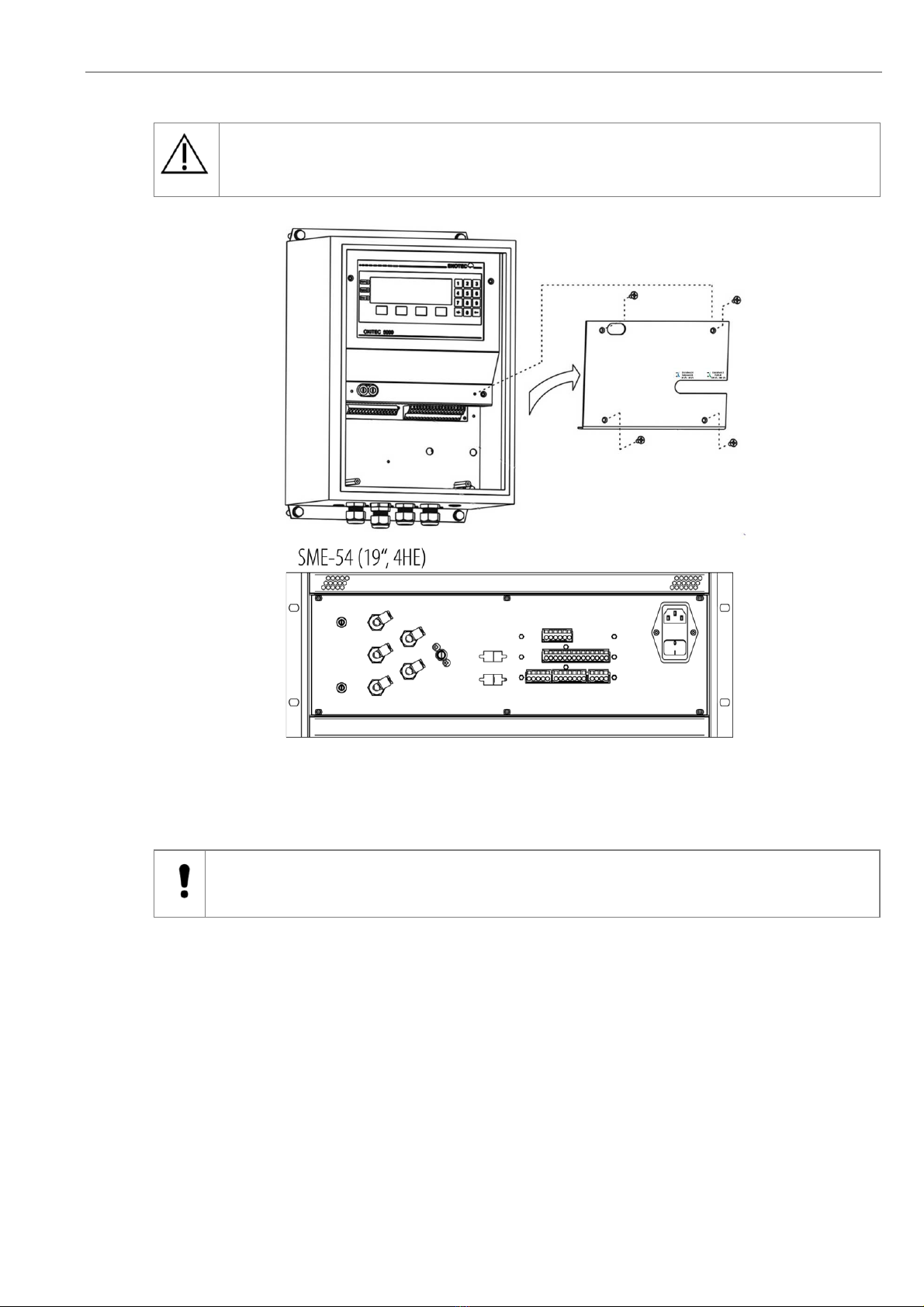
2.3 Access to the Terminals
Warning
Before removing the terminal covers, switch off the mains voltage to the system. Switch the mains volt-
age on only after attaching the terminal cover. After the installation has been completed, live parts may
no longer be accessible.
Figure 6 -Access to the Terminals
2.4 Ferrite Sleeves (EMC)
Caution
In order to avoid cable related disturbances to the electronic unit, the supplied ferrite sleeves must be used.
CE-conformity is invalid if these ferrite sleeves are not fitted!
Installation Installation and Operation Manual - COMTEC
®
6000
12 Doc.-ID: COM6000_11022020_EN
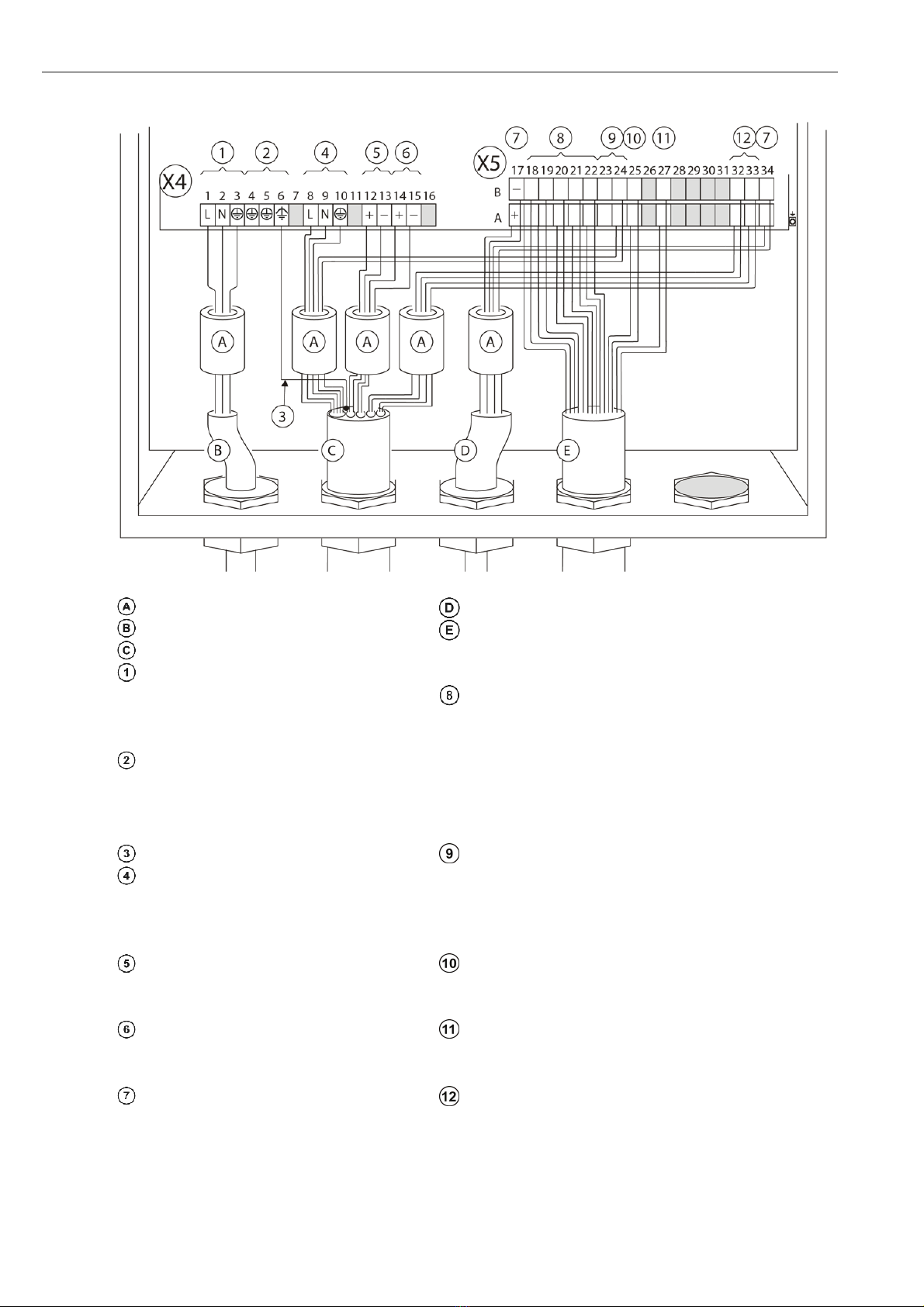
2.5 Wiring diagram of the Electronic Unit
Figure 6 - Wiring diagram of the electronic unit
Ferrite sleeves (Enclosed)
A
nalogue output cable (customer)
Power supply cable (customer) Status signal cable (customer)
Probe signal cable
Internal Power supply
1 L phase
Relay contacts for status signals -
Potential free
2 N neutral wire
3 PE protection earth 18 A/B Maintenance
Grounding
19 A/B System Error
4 PE protection earth 20 A/B Output A O
2
measuring range
5 PE protection earth 21 A/B Limit Alarm 1 (O
2
)
6 PE functional earth 22 A/B Limit Alarm 2 (CO
e
)
Shielding Probe solenoid valve
Power supply probe heater (115V) 23 A
Internal Power supply for probe solenoid
valve (115VAC)
8 L black 23 B
9 N blue 24A L grey
10 PE green/yellow 24B N grey/blue
O
2
-sensor signal Measuring Range O
2
(12..24V DC- External supply)
12 + brown 25A +
13 - brown/white 25B -
Thermocouple (O
2
sensor) Calibration release (12..24V DC - External supply)
14 + green 27A +
15 - white 27B -
Analogue outputs (active 4-20mA) CO
e
sensor
17A + O
2
32A CO
e
sensor
white/red 2
17B - O
2
32B white/red 1
34A +
CO
e
33A CO
e
sensor
red 4
34B
-
CO
e
33B red 3

Installation and Operation Manual - COMTEC®6000 Installation
Doc.-ID: COM6000_11022020_EN 13
2.6 Wiring Diagram of the COMTEC 6000 System
Figure 7 - Wiring diagram of the COMTEC 6000
Installation Installation and Operation Manual - COMTEC
®
6000
14 Doc.-ID: COM6000_11022020_EN
2.7 Installation of the probe
The flue gas temperature, pressure and all other process conditions must be in accordance with the specification.
Leave enough space for insertion/removal of the probe and protection tube (if supplied) and ensure access to the
measuring probe and/or connecting box.
Before cutting a hole in the flue gas duct, make sure that the inside of the duct has enough space for probe installa-
tion and that no soot is blown out nearby or any obstacles are in the way.
For probe lengths exceeding 2000 mm, a support must be mounted inside the duct (every 2 m) to prevent the probe
and mounting tube from flexing or bending. ENOTEC recommends installing the probe horizontally (- 1 ° to - 3 °)
for the fastest possible response time. A vertical (90 °) installation decreases the response time significant.
The ambient temperature at the connection box and
the process temperature must not be exceeded.
Avoid vibrations greater 2g
Maintain the protection class of the connection box. Heavy equipment, ensure proper lifting and carrying
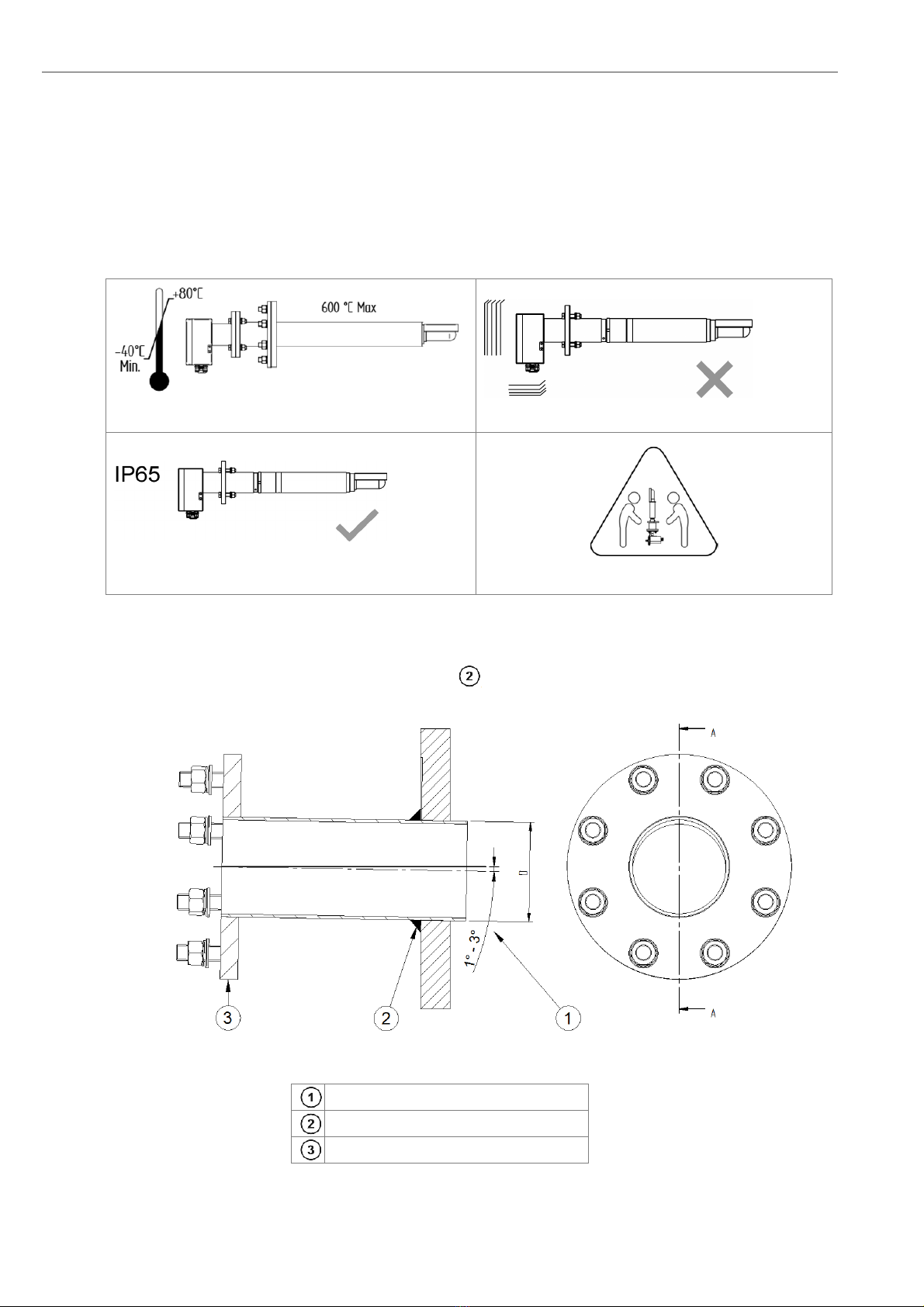
2.8 Mounting of the Counter Flange at the Duct
The flange has to be mounted with an angle of 1° to 3° , so that condensed flue gas elements can flow back into
the duct.
Figure 8 - Mounting of the counter flange at the duct
Pitch of the counter flange
The flange has to be welded gastight.
Counter flange (supplied by customer)
Installation and Operation Manual - COMTEC
®
6000 Installation
Doc.-ID: COM6000_11022020_EN 15
2.9 Adjustment of the Probe Filter Head
Info
Determine the flow direction of the process gas at the place of installation.
Unscrew the retaining ring (clock-
wise) with a hook wrench
Turn the filter head V-shield into the
correct position with a pin wrench.
The V-shield must face the direction of
the flue gas .
Tighten the retainer ring after adjust-
ing the filter head.
Figure 9 - Adjustment of the V-Shield
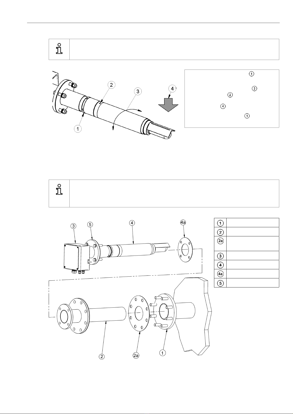
2.10 Probe Protection Tube at the Mounting Flange
Info
Use only new and undamaged gaskets for the installation of the probe. Tighten the nuts firmly, to guaran-
tee the gastight seal of the flange connection. Never leave the probe unheated for longer periods of time
in the running process.
Counter flange
Protection tube
Protection tube flange
gasket
Connection box
O
2
/CO
e
probe
Probe flange gasket
Probe flange
Figure 10 - Mounting of the protection tube at the mounting flange
Installation Installation and Operation Manual - COMTEC
®
6000
16 Doc.-ID: COM6000_11022020_EN
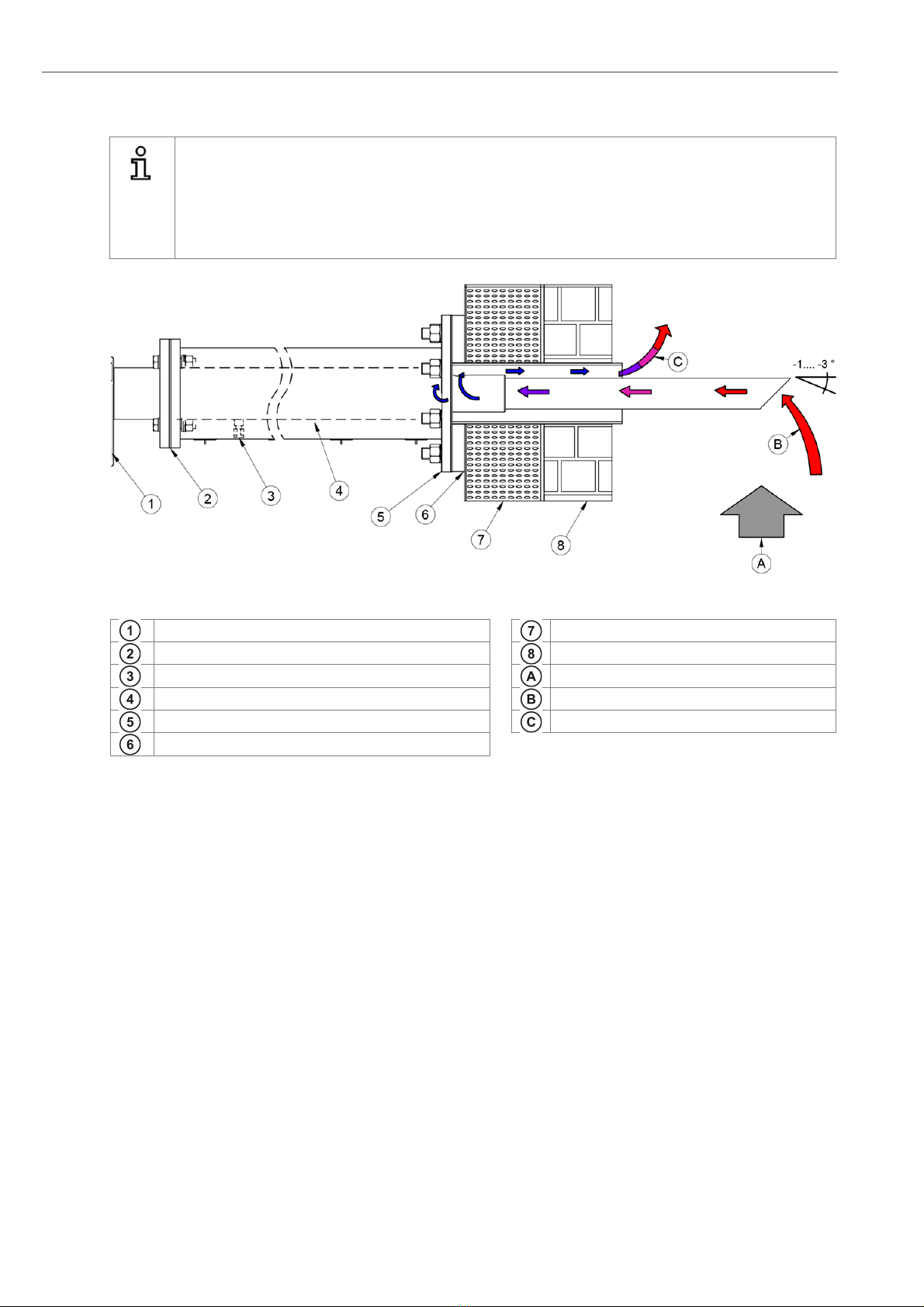
2.11 Insulating the Protection Tube outside the Duct
Info
If a cooling protection tube is used, the part of the protection tube outside the duct wall must be insulated
or heated if necessary. If only a protection tube is in use and not a cooling protection tube, this insulation
may also be
necessary.
Make sure that the gas outlet is not blocked.
Figure 11 -Insulation of the cooling protection tube
Probe connection box
Steel cover
Flange gasket
Duct wall
Suction connection
Flue gas
Cooling tube - Insulate to avoid condensation
Gas entry
Protection tube flange
Gas outlet – do not block
Counter flange welded gas tight at correct angle
Installation and Operation Manual - COMTEC
®
6000 Installation
Doc.-ID: COM6000_11022020_EN 17
2.12 Electrical Connections of the Probe
Info
The Probe Signal Cable FEP-0007/8 has to be connected to the terminal board in the probe terminal box.
Do not connect the shield here.
Figure 12 - Electrical connections of the probe connection box
2.13 Requirements for Pneumatic Cable FEP-0002
Note the minimum bending radius.
FEP-0002R
min
= 138 mm
Temp. during installation
Temp. during operation
1234 6 8
cell thermocouple probe heating
SondenheizungThermoelement
mV mV 115 V ~
blue
7
blau
gr.ye.
gr.ge.schw.
black
-
+
braun
brown
grün
green
+
white
-
ws/br
wh/br
Messzelle
weiss
L
N
910
grau
grey
LN
115 V ~
Magnetventil
solenoid valve
11 12 13 14
1234
RS RH
COe-Sensor
COe-sensor
0,5V 15V
gr.-bl.
gr.-bl.
COe-Sens. Heiz.
COe-sens. heat.
rot
red
rot
red
ws/rt
wh/rd
ws/rt
wh/rd
-
5 °C
Min.
+50 °C
Max.
-40 °C
Min.
+90 °C
Max.

Installation Installation and Operation Manual - COMTEC
®
6000
18 Doc.-ID: COM6000_11022020_EN
2.14 Preparation of the pneumatic Cable
Pneumatic tubing of the pneumatic
cable FEP-0002
Nut
Clamp ring
Support sleeve
Both, the pneumatic tubing for the reference
air (blue) and the test gas (green) have to be
prepared with support sleeves , clamp
rings and nuts .
Figure 13 -Preparation of pneumatic tubes
2.15 Pneumatic Connections of the Probe
Cable gland for Probe Signal Cable (FEP-0007/8)
Blue tubing (Ref. air)
Green tubing (Test gas)
The two pneumatic tubes – blue and green have to be con-
nected at the probe terminal box.
Please follow the color code:
connect the green tubing with the green ring and connect
the blue tubing to the blue ring
Figure 14 - Connection of the pneumatic tubes at the measuring probe
1 2 3

Installation and Operation Manual - COMTEC
®
6000 Installation
Doc.-ID: COM6000_11022020_EN 19
2.16 Pneumatic Connections of Electronic Units
Nr. Tube Pump version Instrument air version
1/4“ Testgas in Testgas in
1/4“ Testgas out Testgas out
1/4“ Reference air in Instrument air in
1/4“ Reference air out Reference air out
1/4“ Test air in
Figure 15 - Bottom view of SME-53 with pneumatic unit
Instrument air version Pump version
Figure 16 - Back view of SME-54 (19” 4HE) showing pneumatic connections.
Nr. Tube Pump version Instrument air version
1/4“ Testgas in Testgas in
1/4“ Testgas out Testgas out
1/4“ Reference air input Instrument air in
1/4“ Reference air output Reference air out
1/4“ Test air input
Regulator reference Air
Regulator test Air
Regulator test Air
Initial Operation Installation and Operation Manual - COMTEC
®
6000
20 Doc.-ID: COM6000_11022020_EN
3 Initial Operation
3.1 Checklist before commissioning the system
Is the system number of the probe identical to the system number of the electronic unit? If not, change the as-
signment.
Does the voltage specified on the name plate correspond to the line voltage? (See section 1.7 - Name Plates)
Is the electrical wiring connected correctly? (See section 2.5 - Wiring Diagram of the Electronic Unit)
Are the pneumatic connections correct and gas tight? (See sections 0 and 0 – Pneumatic Connections)
Make sure that there are no leakages at the probe - e.g. is the counter flange welded gas tight to the duct and
are the flange bolts tightened sufficiently? Are gaskets in use? (See section 2.7 – Installation of the probe)
Do the conditions at site match the specification in the data sheets? (See section A - Technical Data)
3.2 System Power Up
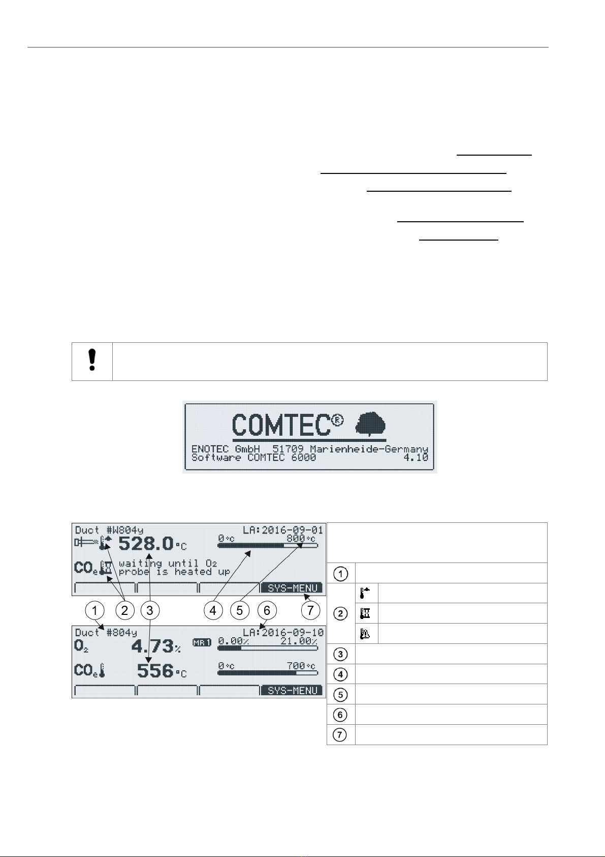
Switch on the line voltage to the system. After a short power up information, the user is prompted to
Select language, set the System date, System time, enter a TAG number and ENOTEC REMOTE code (only if
option ENOTEC REMOTE is factory activated) and the cable length.
The probe heating phase now begins which is followed by the measuring mode.
Caution
Enter the probe cable length correctly! Entering the wrong cable length may result in an incorrect
measurement and could possibly destroy the MXP Sensor.
Figure 17 - System Power up. Note the software version at the bottom right of the display
3.3 Display - Probe Heating Phase
The probe heating phase begins with the heating
up of the O
2
sensor. After this is concluded, the
CO
e
sensor begins its heating up phase.
TAG number
Rising probe temperature
(or) waiting period
(or) heater error
Current temperature
Analogue temperature bar
Setpoint probe temperature
Last access
Softkey title: e.g. System menu
Figure 18 - O
2
and CO
e
sensor heating phase
Table of contents
Other Enotec Analytical Instrument manuals


