Wohler VIS 700 User manual

The Measure of Technology
Manual
HD Service Camera
Wohler VIS 700
Order no. 24105 2017-09-07
99 Washington Street
Melrose, MA 02176
Phone 781-665-1400
Toll Free 1-800-517-8431
Visit us at www.TestEquipmentDepot.com

Contents
2
Table of contents 1General Information..............................4
1.1 Operation Manual Information ....................... 4
1.2 Copyright ....................................................... 4
1.3 Notes ............................................................. 4
1.4 Proper use ..................................................... 5
1.5 Scope of supply ............................................. 5
1.6 Storage and transport.................................... 6
1.7 Information on disposal ................................. 6
1.8Manufacturer ................................................. 6
2Important information ..........................7
3Technical data.......................................9
3.1 Monitor .......................................................... 9
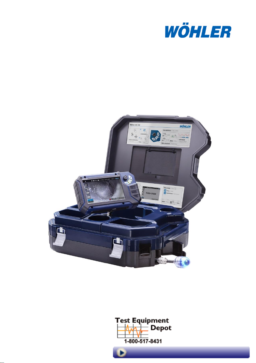
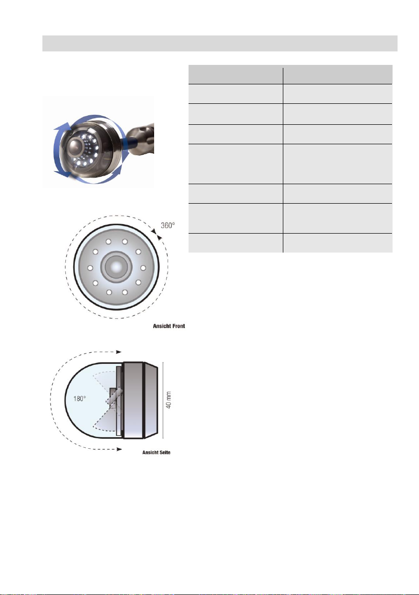
3.2 Wöhler pan & tilt camera head .................... 10
3.3 Camera Rod ................................................ 11
3.4 Electronic meter counter ............................. 11
3.5 Storage ........................................................ 11
3.6 Twinwall hard case ...................................... 11
4Design and function ...........................12
4.1 Video Inspection System ............................. 12
4.2 Monitor ........................................................ 14
5Starting to use your camera system.16
5.1 Attaching the camera head ......................... 16
5.2 Using the monitor ........................................ 16
5.3 Charging the rechargeable battery .............. 19
6Keys and their functions....................20
6.1 On/Off key ................................................... 20
6.2 Video key .................................................... 22
6.3 Image key .................................................... 22
6.4 Joystick ....................................................... 23
7Display elements.................................24
8Displayed position of the camera head
..............................................................25

Contents
3
9Home function.....................................25
10 Digital meter counter..........................25
11 Voice recording ..................................26
12 Live menu............................................26
12.1 Brightness menu .......................................... 26
12.2 Focus menu ................................................. 26
12.3 Comment function ........................................ 27
12.4 System menu ............................................... 29
12.4.1 Activate Wi-Fi and transmit image data to a
mobile terminal device ................................. 29
12.4.2 Settings ........................................................ 31
12.4.3 Locate .......................................................... 31
12.4.4 Saving and deleting images and videos ...... 32
12.4.5 Display images and videos .......................... 33
13 Faults ...................................................34
13.1 Reset ........................................................... 34
13.2 Possible malfunctions .................................. 34
14 Maintenance........................................35
14.1 Information on maintenance ........................ 35
14.2 Replacing the dome of the camera head ..... 35
14.3 Camera head ............................................... 35
14.4 Monitor ......................................................... 35
14.5 Cleaning the viper and the rod ..................... 35
15 Guaranty and Service.........................40
15.1 Guaranty ...................................................... 40
15.2 Service ......................................................... 40
16 Declaration of conformity..................41

General Information
4
1General Information
1.1 Operation Manual In-
formation
This operation manual allows you to work safely
with the Wohler VIS 700. Please keep this manual
for your information.
The Wohler VIS 700 should be employed by pro-
fessionals for its intended use only.
Liability is void for any damages caused by not
following this manual.
1.2 Copyright
Without previous authorization of Wohler it is not
allowed to reproduce, copy or translate this man-
ual or part of this manual.
1.3 Notes
WARNING!
Not following this warning can cause injury or
death.
CAUTION!
Highlights risks that can lead to damage occurring
to the device.
NOTE!
Highlights tips and other useful information.

General Information
5
1.4 Proper use
The Camera is designed to visually inspect and
document the condition of pipes and shafts, for
example in flue gas systems, ventilation systems
as well as for inspecting underground pipes etc.
The Camera is designed to be used by trained
specialists only.
Any other use is considered improper use.
1.5 Scope of supply
Device
Scope of supply
Wohler VIS 700 HD
Service Camera
Monitor
Ø 1.5 inch pan and tilt
color camera head,
pluggable
SD card 32 GB
Viper with
100 ft camera rod and
monitor cable (5 ft)
3 replacement plastic
domes
1 anti-slide mat
1 USB power supply
with USN-C-cable
Twinwall hard case

General Information
6
1.6 Storage and transport
To avoid damage occurring during transport it is
1.7 Information on disposal
1.8 Manufacturer
imperative that the complete system is transport-
ed in the original case designed for the purpose.
Electronic equipment does not belong into domes-
tic waste, but must be disposed in accordance
with the applicable statutory provisions.
You may hand in any defective batteries taken out
of the unit to our company as well as to recycling
places of public disposal systems or to selling
points of new batteries or storage batteries.

Important information
7
2Important information
Eye protection
WARNING!
Never point a connected camera head at your own
or somebody else's eyes when the monitor is
switched on. The LEDs are extremely bright and
can dazzle.
WARNING!
Guide the rod with due care and attention. As the
rod is made of flexible material, it can make whip-
ping movements if it slips. Protect your eyes in
particular.
Working environment
WARNING!
Only place the camera on firm level ground and
ensure a secure position of camera and user, es-
pecially when working in high altitude, e.g. when
working on the roof.
WARNING!
Make sure that the parts that you are going to in-
spect are no live parts.
CAUTION!
Protect the camera head against oil and acid.
Never use the camera head and rod to push ob-
structions.
Operating Temperature
CAUTION!
Do not use the camera in temperatures above
40°C. High temperatures can damage the camera.

Important information
8
Resistance to water
CAUTION!
Only the camera head and the rod are waterproof
Keep the camera system dry and protect it from
water!
Resistance to impacts
CAUTION!
The camera system is not impact resistant. Do not
throw or allow the case to fall!
Accessories
CAUTION!
Use only original Wöhler accessories and spare
parts!
Strong magnetic or electric
fields
NOTE!
Do not use the camera near television towers,
mobile radio equipment or other sources of mag-
netic or electric fields, as these may impair the
quality of the displayed image.
Extraneous influences
NOTE!
Extraneous influences such as static discharges
can cause the device to malfunction. If a malfunc-
tion occurs, switch the monitor off and on again.

Technical data
9
3Technical data
3.1 Monitor
Fig. 1: Monitor
Description
Data
Dimensions housing
0.3 x 0.2 x 0.1 inch
Weight
1.9 lb
TFT display
7"/ 16:9 format
1280 x 800 pixel
Charging cable
USB-C 5 V/3 A
Power supply
3.7 V,
11400 mAh rechargea-
ble Li-Ion battery
Battery operating
time
Up to 4 h (battery status
in display)
Operating Tempera-
ture
32 - 104 °F
Storage Tempera-
ture
- 4 – 122°F

Technical data
10
3.2 Wöhler pan & tilt cam-
era head
Fig. 2: Pan & tilt camera head
Fig. 3: Pans through 360°
Fig. 4: Tilts 180°
Description
Data
Classification Type
1/2.7" COLOR CMOS
Focus distance
1 inch ... ∞
Light source
10 white LEDs
Protection
Waterproof to IP 67 (up
to 1 m depth for 30
mins.)
Dimensions
Ø 1,5 inch
Frequency of the
integrated emitter
8.9 kHz
Angle of detection
75°

Technical data
11
3.3 Camera Rod
Description
Data
Length
100 ft.
Connection cable to
the monitor
4,92 ft
3.4 Electronic meter coun-
ter
Description
Data
Resolution
1 inch
Max. deviation
5 % of reading
3.5 Storage
Description
Data
Memory
If you are using a
memory card other
than the one included
in the scope of supply,
you must format it on
a PC before using it
with the camera. FAT
32
Max.
32 GB
Technology
SD or SDHC,
maximum speed 10
Record Capacity
Approx. 3 GB/h
Video Resolution
1280 x 720 HD, max.
25 fps.
Video format
AVI (H264)
3.6 Twinwall hard case
Description
Data
Dimensions
7 x 17 x 20 in.
Total weight with mon-
itor, camera head and
rod
22 lb

Design and function
12
4Design and function
4.1 Video Inspection System
Fig. 5: Wohler VIS 700 HD Service Camera
3
8
5
6
7
2
4
7
8
1
9

Design and function
13
Legend:
1
Monitor
2
Anti-glare protection (stored in the case)
3
Space for accessories, charging cable, camera head etc.
4
Opening for the camera head
5
Camera head
6
Lower shell with viper and rod (inside)
7
Locks of the camera case
8
Locks of the lower shell
9
Monitor support

Design and function
14
4.2 Monitor
Fig. 6: Monitor
Fig. 7: Bottom side of the monitor with USB and SD card slot
1
1
1
1
2
3
6
7
8
9
10
4
11
5

Design and function
15
Legend:
1
Fixing holes for anti-glare protection
2
Handle, in the picture inserted in the slot of the housing
3
Bottom side of the monitor with terminal strip
4
Loudspeaker
5
Microphone
6
CTIA standard connection for headset with headphone and microphone
7
HDMI connection for external monitor
8
SD Card slot
9
USB port for stick
10
USB port for charging cable
11
Notch for placing the monitor on the connecting rail of the case

Starting to use your camera system
16
5Starting to use your camera system
5.1 Attaching the
camera head
Open the cover of the camera head opening
(Fig. 5, part 4)
Carefully pull the rod out of the case.
If it is not already connected to the rod, con-
nect the camera head to the rod as follows:
Inset the five-pin connector of the camera rod
into the socket of the camera head.
Then screw together the threaded parts of the
camera head and camera rod.
CAUTION!
The connection is only waterproof when the con-
nectors are joined together properly.
5.2 Using the monitor
NOTE!
When the monitor is stored in the case as envisaged the joystick is located at the
bottom left. This position makes it possible to operate the joystick with the left hand
and guide the camera rod with the right hand. If the monitor is removed from the
case, it is recommended that right-handed users turn the monitor around so that they
can operate the joystick with their right hand.
Fig. 8: Press the catch from the
front to release the monitor from its
secured position in the case
To release the monitor from its secured posi-
tion in the case, press the catch from the front.

Starting to use your camera system
17
Fig. 9: Press down on the catch
from above to lower the monitor
into the case.
To return the monitor to its transport position,
press on all four corners of the monitor or
press down vertically on the catch.
CAUTION!
If there is any resistance when pushing down on
the monitor, check the connection cable has been
placed under the monitor properly rolled up without
any kinks
Fig. 10: You can turn and tilt the
monitor
When released from the case you can tilt the moni-
tor up and down as you wish and turn it around its
longitudinal axis. Locking points ensure the camera
is held in a stable position.
Fig. 11: Monitor removed from the
case
It is also possible to release the raised monitor
from the holder and hold it in your hands.
Fig. 12: Press the lever to release
the monitor from the holder
Proceed as follows to release the monitor from the
holder:
Position the monitor upright in the holder.
Press against the lever on the rear of the moni-
tor.
At the same time pull the monitor out of the
holder.

Starting to use your camera system
18
Handle
Fig. 13: With the handle pulled out
it is possible to hold and operate
the monitor with one hand.
It is possible to pull out a handle to allow you to
hold the monitor in your right hand and operate the
joystick with your right hand at the same time.
Fig. 14: The pushbutton to release
and pull out the handle is indicated
by an arrow
To pull out the handle press the black pushbut-
ton on the top of the monitor and slide the
handle to the right at the same time.
Anti-glare visor
Remove the anti-glare visor from of the case
lid. It is located in the compartment behind the
lower part of the Short Guide.
Insert both pins of the anti-glare visor into the
corresponding fixing holes immediately above
or below the display to suit your working posi-
tion. Magnets on the ends of the pins ensure
the visor is securely fixed in position.

Starting to use your camera system
19
5.3 Charging the rechargeable battery
WARNING!
Danger of death by electrocution!
Never touch a mains plug with wet hands!
Do not expose the power pack to moisture!
Never pull the cable to remove the power pack
from the socket outlet - it could rip out the cable!
Operate the power pack only when the mains
power supply is the same as the voltage stated on
the rating plate!
Fig. 15: Battery charge icon 60%
A battery charge icon is on the right of the icon
ribbon. The charge level is displayed in either blue
or orange (≤ 20%).
Recharge the rechargeable battery if the charge
level is displayed in red (≤ 10%).
To charge the battery, connect the monitor to
the mains using the USB power pack included
in the scope of supply.
To do so, insert the USB C connector into the
USB port on the bottom of the monitor.
Fig. 17: Keys and charge level
indicated when charging
When the camera system is switched off the im-
age and video keys flash red during the charging
process.
The image and video keys light up red when the
battery is fully charged.
The camera system remains fully functional during
the battery charging process.
NOTE!
If possible, recharge the battery when the camera
system is switched off. This increases the opera-
tional lifetime of the rechargeable battery.
The keys do not flash if the battery is recharged with
the camera system switched on. A connector sym-
bol is displayed in the rechargeable battery display.
Fig. 16: USB port indicated by an
arrow

Keys and their functions
20
6Keys and their functions
Fig. 18: Monitor keys
6.1 On/Off key
NOTE!
The ventilation fan is audible at irregular intervals when the camera is in operation.
Switching on the system
When the system is switched off, press and
hold the ON/Off key for approx. one second.
The ON/Off key then lights up green, the im-
age and video keys light up blue.
After approx. five seconds the LEDs light up on the
camera. The Home screen is displayed followed by
the camera image.
NOTE!
It is possible to turn the monitor through 180°. The
icon and information ribbons in the monitor are
automatically aligned according to the monitor po-
sition. It is also possible to turn the viewing posi-
tion of the screen by slightly turning the monitor.
Switching the system off
Press and hold the On/Off key for approx. two
seconds until the system switches off.
On/Off key/
Menu key
Image key
Video key
Joystick
Other manuals for VIS 700
5
Table of contents
Other Wohler Analytical Instrument manuals

Wohler
Wohler VE 200 User manual

Wohler
Wohler Lokator L 24 User manual

Wohler
Wohler VE 400 User manual

Wohler
Wohler VIS 700 User manual

Wohler
Wohler VE 200 User manual

Wohler
Wohler Camera Viper VIS 2000 User manual

Wohler
Wohler VIS 200 User manual

Wohler
Wohler VIS Camera Viper 36 User manual

Wohler
Wohler VIS 400 User manual

Wohler
Wohler VIS 2000 User manual