Icom IC-M71 User manual

INSTRUCTION MANUAL
VHF MARINE TRANSCEIVER
New2001
iM71

i
New2001
DECLARATION
OF CONFORMITY
We Icom Inc. Japan
1-1-32, Kamiminami, Hirano-ku
Osaka 547-0003, Japan
Kind of equipment:
VHF MARINE TRANSCEIVER
This compliance is based on conformity with the following harmonised
standards, specifications or documents:
i) EN 301 178-2 V1.1.1 (2000-8)
ii) EN 60945 2002
iii) EN 60950-1 2001
iv) EN 300 698-2 V1.1.1 (2000-8)
v) EN 300 698-3 V1.1.1 (2001-5)
vi)
vii)
Type-designation:
iM71
Signature
H. Ikegami
General Manager
Dűsseldorf 27th Dec. 2005
Himmelgeister straße 100
D-40225 Dűsseldorf
Icom (Europe) GmbH
Authorized representative name
Place and date of issue
Version (where applicable):
Declare on our sole responsability that this equipment complies the
essential requirements of the Radio and Telecommunications Terminal
Equipment Directive, 1999/5/EC, and that any applicable Essential Test
Suite measurements have been performed.
0560
CE Versions of the IC-M71 which display the
“CE” symbol on the serial number seal, comply
with the essential requirements of the Europe-
an Radio and Telecommunication Terminal Di-
rective 1999/5/EC.
This warning symbol indicates that this equipment
operates in non-harmonised frequency bands and/
or may be subject to licensing conditions in the
country of use. Be sure to check that you have the
correct version of this radio or the correct program-
ming of this radio, to comply with national licensing
requirement.

ii
IN CASE OF EMERGENCY
If your vessel requires assistance, contact other vessels and
the Coast Guard by sending a distress call on Channel 16.
USING CHANNEL 16
DISTRESS CALL PROCEDURE
1. “MAYDAY MAYDAY MAYDAY.”
2. “THIS IS ������ ” (name of vessel)
3. Say your call sign or other indication of the
vessel.
4. “LOCATED AT ����� ” (your position)
5. State the nature of the distress and assis-
tance required.
6. Give any other information which might facil-
itate the rescue.
RECOMMENDATION
CLEAN THE TRANSCEIVER THOROUGHLY WITH FRESH
WATER after exposure to saltwater, and dry it before opera-
tion. Otherwise, the transceiver’s keys, switches and control-
lers may become inoperable due to salt crystallization.
NOTE: DO NOT wash the transceiver in water if there is any
reason to suspect the waterproofing may not be effective. For
example, in cases where the transceiver/battery pack is cracked
or broken, or has been dropped, or when the battery pack is de-
tached from the transceiver.

FOREWORD
Thank you for purchasing this Icom radio. The IC-M71 vhf ma-
rine transceiver is designed and built with Icom’s state of the
art technology and craftsmanship. With proper care this product
should provide you with years of trouble-free operation.
IMPORTANT
READ ALL INSTRUCTIONS carefully and com-
pletely before using the transceiver.
SAVE THIS INSTRUCTION MANUAL—This
instruction manual contains important operating instructions
for the IC-M71.
EXPLICIT DEFINITIONS
WORD DEFINITION
RDANGER Personal death, serious injury or an
explosion may occur.
RWARNING Personal injury, fire hazard or electric
shock may occur.
CAUTION Equipment damage may occur.
NOTE
If disregarded, inconvenience only. No risk
of personal injury, fire or electric shock.
FEATURES
Submersible construction
Built tough to withstand the punishing marine environ-
ment, the IC-M71’s submersible construction meets IPX8
of the corresponding International Standard IEC 60529
(2001) while using BP-245N.
In addition, the new speaker grill structure with a water
self-draining function is helpful for draining water or sea-
water easily.
Dualwatch and tri-watch functions
Convenient functions that allow you to monitor the dis-
tress channel (Ch 16) while receiving one other channel
of your choice (dualwatch), or while receiving one other
channel of your choice and the call channel (tri-watch).
See p. 16 for details.
Large, easy-to-read LCD
With the generous dimensions of 22.5(H) × 31.5(W) mm,
the IC-M71’s function display is easy to read and shows
operating conditions at a glance. Backlighting and con-
trast can be adjusted to suit your preferences.
Simple operation
The volume knob is on top of the radio, while the channel
buttons are on the front panel. This allows for convenient,
one-handed operation.
iii
New2001

iv
PRECAUTION
New2001
RWARNING! NEVER connect the transceiver to an
AC outlet. This may pose a fire hazard or result in an elec-
tric shock.
RWARNING! NEVER hold the transceiver so that
the antenna is closer than 2.5 cm from exposed parts of the
body, especially the face or eyes, while transmitting. The
transceiver will perform best if the microphone is 5 to 10 cm
away from the lips and the transceiver is vertical.
NEVER connect the transceiver to a power source other
than the BP-245N. Such a connection will ruin the transceiv-
er.
AVOID using or placing the transceiver in direct sunlight or
in areas with temperatures below –15°C or above +55°C.
KEEP the transceiver out of the reach of children.
KEEP the transceiver at least 0.9 meters away from your
vessel’s magnetic navigation compass.
MAKE SURE the flexible antenna and battery pack are
securely attached to the transceiver, and that the antenna
and battery pack are dry before attachment. Exposing the in-
side of the transceiver to water will result in serious damage
to the transceiver.
BE CAREFUL! The IC-M71 employs submersible con-
struction (1.5 m depth for 30 min.). However, once the transceiv-
er has been dropped, waterproofing cannot be guaranteed
due to the fact that the transceiver may be cracked, or the
waterproof seal damaged, etc.
Icom, Icom Inc. and the Icom logo are registered trademarks of Icom Incor-
porated (Japan) in the United States, the United Kingdom, Germany, France,
Spain, Russia and/or other countries.

v
New2001
TABLE OF CONTENTS
IN CASE OF EMERGENCY ���������������� ii
RECOMMENDATION ������������������� ii
FOREWORD����������������������� iii
IMPORTANT����������������������� iii
EXPLICIT DEFINITIONS ����������������� iii
FEATURES ����������������������� iii
PRECAUTION ���������������������� iv
TABLE OF CONTENTS ������������������ v
1 OPERATING RULES …………………………………………… 1
2 SUPPLIED ACCESSORIES AND ATTACHMENTS ……… 2–3
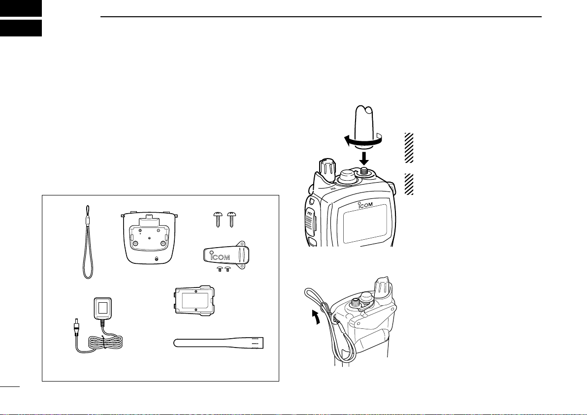
nSupplied accessories ���������������� 2
nAttachments �������������������� 2
3 PANEL DESCRIPTION ……………………………………… 4–6
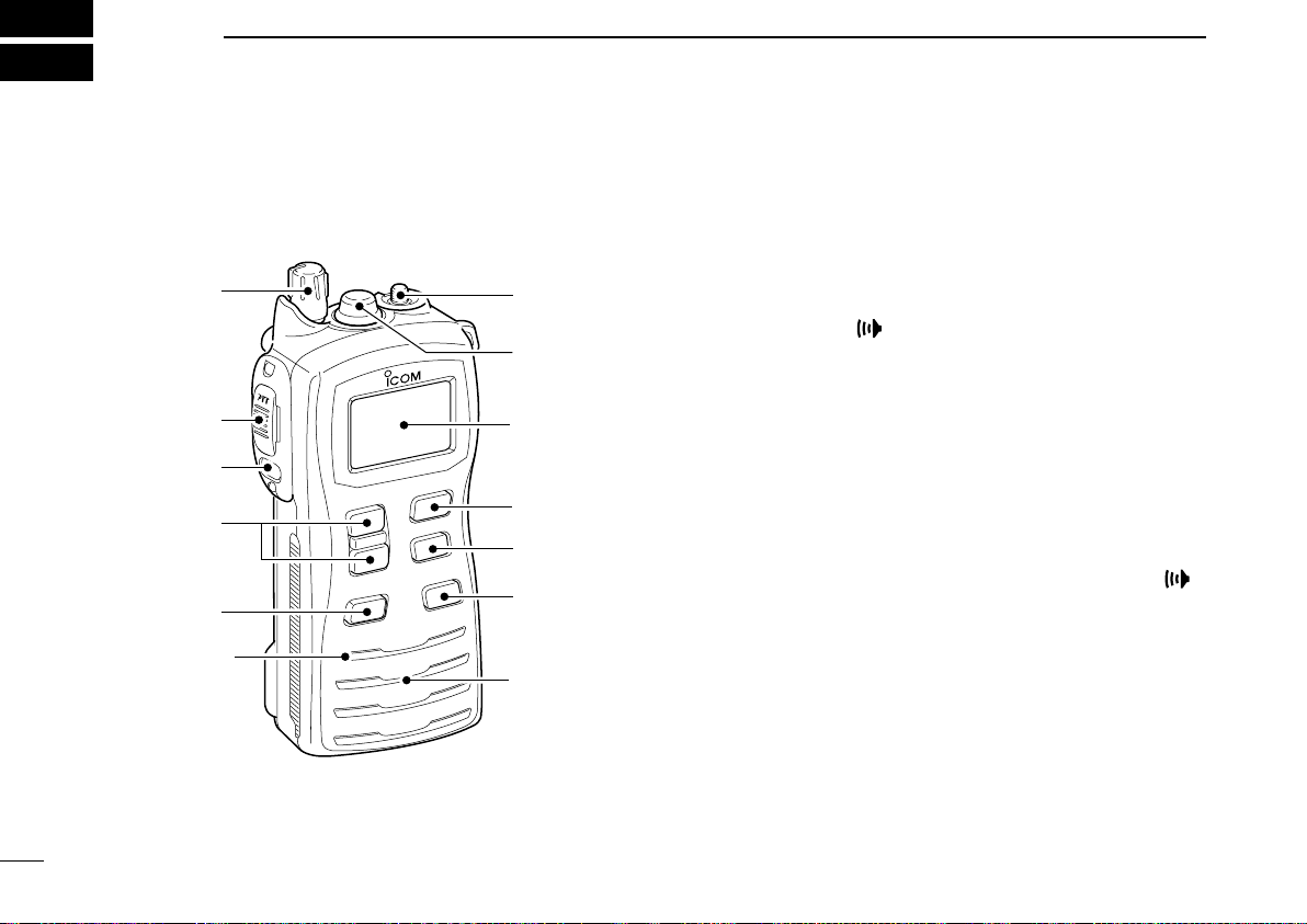
nFront, top and side panels �������������� 4
nFunction display������������������� 5
4 BASIC OPERATION………………………………………… 7–13
nChannel selection ������������������ 7
nReceiving and transmitting �������������� 9
nCall channel programming ��������������10
nLock function ��������������������10
nMonitor function �������������������10
nAdjusting the squelch level ��������������11
nBacklighting function �����������������11
nVoice scrambler operation ��������������11
nVOX function ��������������������12
nAquaQuake water draining function ����������12
nChannel naming ������������������12
5 SCAN OPERATION (except dutch versions) ………… 14–15
nScan types ���������������������14
nSetting TAG channels ����������������15
nStarting a scan �������������������15
6 DUALWATCH/TRI-WATCH (except Dutch versions) ………16
nDescription ���������������������16
nOperation ���������������������16
7 SET MODE …………………………………………………… 17–22
nSET mode programming ���������������17
nSET mode items ������������������18
8 BATTERY CHARGING …………………………………… 23–27
nBattery cautions �������������������23
nSupplied battery charger ���������������25
nOptional battery chargers���������������26
nAttachment ���������������������28
nDetachment ��������������������28
9 OPTIONAL SWIVEL BELT CLIP ………………………………28
10 OPTIONAL SPEAKER-MICROPHONE ………………………29
nHM-125 descriptions �����������������29
nAttachment ���������������������29
11 TROUBLESHOOTING ……………………………………………30
12 VHF MARINE CHANNEL LIST …………………………………31
13 SPECIFICATIONS…………………………………………………32
14 OPTIONS …………………………………………………………33

1
1
OPERATING RULES
D Priorities
• Read all rules and regulations pertaining to priorities and
keep an up-to-date copy handy. Safety and distress calls
take priority over all others.
• You must monitor Channel 16 when you are not operating
on another channel.
• False or fraudulent distress calls are prohibited under law.
D Privacy
• Information overheard but not intended for you cannot law-
fully be used in any way.
• Indecent or profane language is prohibited.
D Radio licenses
(1) SHIP STATION LICENSE
When your craft is equipped with a VHF FM transceiver, you
must have a current radio station license before using the
transceiver. It is unlawful to operate a ship station which is
not licensed.
Inquire through your dealer or the appropriate government
agency for a Ship-Radiotelephone license. This license in-
cludes the call sign which is your craft’s identification for radio
purposes.
(2) OPERATOR’S LICENSE
A restricted Radiotelephone Operator Permit is the license
most often held by small vessel radio operators when a radio
is not required for safety purposes.
The Restricted Radiotelephone Operator Permit must be
posted near the transceiver or be kept with the operator. Only
a licensed radio operator may operate a transceiver.
However, non-licensed individuals may talk over a transceiv-
er if a licensed operator starts, supervises, ends the call and
makes the necessary log entries.
A current copy of the applicable government rules and reg-
ulations is only required to be on hand for vessels in which
a radio telephone is compulsory. However, even if you are
not required to have these on hand it is your responsibility
to be thoroughly acquainted with all pertinent rules and reg-
ulations.
1

2
New2001
SUPPLIED ACCESSORIES AND ATTACHMENTS
2
nSupplied accessories
The following accessories are supplied: Qty.
qHandstrap �������������������� 1
wBattery charger������������������ 1
eScrews for the battery charger (M3.5×30) ������� 2
rBelt clip (with screws) ��������������� 1
tAC adapter* ������������������� 1
yLi-Ion battery pack ���������������� 1
uFlexible antenna ����������������� 1
*Not supplied with some versions.
q w e
r
t y
u
(Different type is supplied
depending on the version)
nAttachments
DFlexible antenna
Connect the supplied flexible an-
tenna to the antenna connector.
CAUTION: Transmitting without
an antenna may damage the
transceiver.
NEVER HOLD by the antenna
when carrying the transceiver.
DHandstrap
Pass the handstrap through the
loop on the top corner of the trans-
ceiver as illustrated at left.
Facilitates carrying.

3
2
SUPPLIED ACCESSORIES AND ATTACHMENTS
New2001
DBattery pack
qAttach the battery pack into the transceiver as below.
wLock the battery pack with the latch.
CAUTION:
NEVER attach or detach the battery pack when wet.
Be careful when releasing the latch. Because the latch is
tightly locked, don’t use a finger nail to open it— you may
injure yourself. Instead, use something relatively flat, like
the edge of a coin or the tip of a screwdriver, to carefully
release the latch.
DBelt clip
Attach the belt clip to the transceiver as illustrated below.
Supplied screws
2

4
New2001
PANEL DESCRIPTION
3
nFront, top and side panels
q
w
e
r
t
Microphone
!0
o
i
u
y
Speaker
Function
display
(p. 5)
qVOLUME CONTROL [VOL]
Turns power ON and adjusts the audio level.
wPTT SWITCH [PTT]
Push and hold to transmit; release to receive.
e MONITOR KEY [ ]
• Manually opens the squelch for monitoring the chan-
nel while pushed and held. (p. 10)
• Push this switch, then adjust the squelch level with
[Y]/[Z]. (p. 11)
• While pushing and holding this switch, turn power ON to
enter the SET mode. (p. 17)
rCHANNEL UP/DOWN KEYS [Y]/[Z]
• Selects an operating channel. (pgs. 7–9)
• Selects the SET mode condition of the item. (p. 17)
• Selects the SET mode item when pushed with [ ].
(p. 17)
• Checks TAG channels or changes scanning direction
during scan. (p. 15)
tCHANNEL 16 KEY [16•C]
• Selects Channel 16 when pushed. (p. 7)
• Selects call channel when pushed for 1 sec. (p. 7)
•
Enters call channel write mode when the call channel
is selected and this key is pushed and held for 3 sec.
(p. 10)

5
3
PANEL DESCRIPTION
New2001
yTRANSMIT POWER/LOCK KEY [H/L•LOCK]
• Selects high, middle or low power when pushed. (p. 9)
• Toggles the lock function ON/OFF when pushed and
held for 1 sec. (p. 10)
uSCAN KEY [SCAN•DUAL]
• Starts and stops normal or priority scan when pushed.
(pgs. 14, 15)
•
Enters watch mode when pushed and held for 1 sec. (p. 16)
iDIAL KEY [DIAL]
• Selects the regular channels when pushed. (p. 8)
• Selects the U.S.A.*, International, or ATIS†channel group
when pushed and held for 1 sec. (p. 8)
-
The function display shows which channel group is active.
*Available with the UK versions only.
†Available with the German and Dutch versions only
• Push to return to the condition before selecting the chan-
nel when the priority channel or the call channel is select-
ed.
oSPEAKER-MICROPHONE CONNECTOR [SP MIC]
Connects the optional external speaker-microphone or
headset.
NOTE: Attach the [SP MIC] cap when the optional
speaker-microphone or headset is not used.
!0 ANTENNA CONNECTOR
Connects the supplied antenna.
nFunction display
q
we
r
t
yu
i
o
!0 !1
!2
!3
!4
!5
qCHANNEL NUMBER READOUT
• Indicates the selected operating channel number.
• In the SET mode, indicates the selected condition.
• “DUP” appears when a duplex channel is selected.
w TAG CHANNEL INDICATOR (p. 15)
Appears when TAG channel is selected.
e BATTERY INDICATOR
Indicates remaining battery power.
Indication
Full Middle Charging
required No battery
Battery level
blinks when the battery is overcharged
(or over voltage)
.
3

6
3PANEL DESCRIPTION
New2001
r MONITOR INDICATOR (p. 10)
Appears when the monitor function is activated.
t DUALWATCH/TRI-WATCH INDICATORS (p. 16)
“DUAL” blinks during dualwatch; “TRI” blinks during tri-
watch.
y VOX INDICATOR (p. 12)
Appears when the VOX function is used.
u SCRAMBLER INDICATOR (pgs. 11, 22)
Appears when the voice scrambler is activated.
*The voice scrambler function is available with some versions
only.
i CHANNEL NAMING
• Indicates or scrolls operating channel name or comment.
(p. 13)
• In the SET mode, indicates or scrolls the selected item.
(pgs. 17–22)
o LOCK INDICATOR (p. 10)
Appears when the lock function is activated.
!0 ATIS INDICATOR (p. 8)
Appears when the channel group, which ATIS function is
activated, is selected.
• Available with the German and Dutch versions only.
!1 CALL CHANNEL INDICATOR (p. 7)
Appears when the call channel is selected.
!2 CHANNEL GROUP INDICATOR (p. 8)
“USA*” appears when U.S.A.; “INT” appears when Inter-
national channel group is selected.
*Available with the UK versions only.
!3 TRANSMIT POWER INDICATORS (p. 9)
• “LOW” appears when low power is selected.
• “MID” appears when middle power is selected.
• No indication appears when high power is selected.
!4 TRANSMIT INDICATOR (p. 9)
Appears during transmit.
!5 BUSY INDICATOR (pgs. 9, 10)
Appears when a signal is received or squelch is open.

7
4
BASIC OPERATION
3
4
nChannel selection
IMPORTANT!: Prior to using the transceiver for the first
time, fully charge the battery pack. This will help maximize
the capability and life of the battery. To avoid damage to
the transceiver, turn the radio OFF while charging.
DChannel 16
Channel 16 (Distress channel) is used for establishing initial
contact with another station and for emergency communi-
cations. Channel 16 is automatically monitored during both
dualwatch and tri-watch. While standing by, you must moni-
tor Channel 16.
qPush [16•C] to select Channel 16.
wPush [DIAL] to return to the condition before select-
ing Channel 16, or push [Y]/[Z]to select the operating
channel.
Push
DCall channel
Call channel is the leisure-use call channel. Each regular
channel group has separate call channels. In addition, the
call channel is monitored during tri-watch. The call channels
can be re-programmed (p. 10) and may be used to store your
most often used channels in each channel group for quick re-
call.
qPush and hold [16•C] for 1 sec. to select the call channel.
• “CALL” and the call channel number appear.
• Call channel can be re-programmed. See the “Call channel
programming” on p. 10 for details.
w
Push [DIAL] to return to the condition before selecting Call
channel, or push [Y]/[Z]to select the operating channel.
Push
for 1 sec.
Channel 16 is programmed
as a default setting.
(depending on version)

DU.S.A., International and ATIS channels
The IC-M71 has U.S.A.,* International and ATIS†channels.
You must select the proper channels for the operating area.
*Available with the UK versions only.
†Available with the German and Dutch versions only.
qPush [DIAL] to select the regular channel.
wPush [Y]/[Z]to select a channel.
• “DUP” appears for duplex channels.
eTo change the channel group, push and hold [DIAL] for
1 sec.
• Repeat until you reach the desired channel group.
Push for 1 sec. Push for 1 sec.
U.S.A. channel*
International channel
ATIS channel
†
8
4BASIC OPERATION
New2001

9
4
BASIC OPERATION
New2001
4
nReceiving and transmitting
CAUTION: Transmitting without an antenna may
damage the transceiver.
q Rotate [VOL] clockwise to turn power ON.
• Opening comment scrolls across the function display. (p. 13)
• Push [16•C] to skip the opening comment indication.
w Set the volume and squelch level.
➥Push [ ], and push [Z]to open the squelch.
➥Rotate [VOL] to set the volume level.
➥Push [ ], and push [Y]/[Z]to set the squelch level.
e Push [Y]/[Z]to select the desired channel.
- When receiving a signal, “ ” indicator appears while audio
is emitted from the speaker.
- Further adjustment of [VOL] may be necessary at this point.
r
Push [H/L•LOCK] to select the output power, if necessary.
- “LOW” appears when low power is selected; “MID” appears
when middle power is selected; no indication when high power
is selected.
- Choose low or mid. power to conserve battery power, choose
high power for longer distance communications.
- Some channels are for low power only.
t Push and hold [PTT] to transmit, and speak into the micro-
phone.
- The transmit indicator appears while transmitting.
- Channel 70 cannot be used for transmission.
y Release [PTT] to receive.
IMPORTANT: To maximize the readability of your trans-
mitted signal, pause a second after pushing [PTT], hold
the microphone 5 to 10 cm from your mouth, and speak
into the microphone using a normal voice level.
NOTE: The transceiver has a power save function to con-
serve the battery power. The power save function activates
automatically when no signal is received for 5 sec.
Microphone
Speaker
rSet output power
tPush to transmit
yRelease to receive qPower ON
wSet volume
wSet the squelch
level
wSet the squelch
level
eSelect the
channel

10
4BASIC OPERATION
New2001
nCall channel programming
The call channel key is used to select Channel 16 by default
(depending on versions), however, you can program your most
often-used channel in each channel group for quick recall.
q
Push and hold [DIAL] for 1 sec. several times to select the
desired channel group (INT, USA, ATIS) to be programmed.
wPush and hold [16•C] for 1 sec. to se-
lect the call channel.
•
“CALL” and call channel number appear.
e
Push and hold [16•C] again for 3 sec.
(until a long beep changes to 2 short
beeps) to enter call channel program-
ming condition.
• Call channel number to be programmed
blinks.
rPush [Y]/[Z]to select the desired
channel.
tPush [16•C] to program the displayed
channel as the call channel.
• The call channel number stops blinking.
nLock function
This function electronically locks all keys (except for [PTT], [ ]
and [H/L•LOCK])to prevent accidental channel changes and
function access.
➥Push [H/L•LOCK] for 1 sec. to turn the lock function ON
or OFF.
Push
for 1 sec.
Appears while the lock
function is in use.
nMonitor function
The monitor function releases the noise squelch mute to
check the volume level. See p. 19 for details of the monitor
switch action.
➥Push and hold [ ] for 1 sec. to activate the monitor func-
tion.
• “ ” and “ ” appear and audio is emitted.
Push
for 1 sec.
Appears while the
monitor function is
in use.

11
4
BASIC OPERATION
New2001
4
nAdjusting the squelch level
To adjust the IC-M71’s squelch level, use the [Y]/[Z]keys
as desired below. In order to receive signals properly, as well
as for the scan to function effectively, the squelch must be
adjusted to the proper level.
qPush [ ], then adjust the squelch level with [Y]/[Z].
- “SQL” and the squelch level are displayed.
- There are 11 squelch levels to choose from: OP is completely
open; 10 is tight squelch; 1 is loose squelch level.
- When no key is pushed for 5 sec., the transceiver returns to
normal condition.
wPush [ ] again to return to normal operating mode.
Push Shows the squelch
level.
Appears during squelch
level adjustment
nBacklighting function
This function is convenient for night-time operation. The back-
lighting can be turned OFF in the SET mode. (p. 19)
➥Push any key other than [PTT] to turn the backlighting
ON.
• The backlighting is automatically turned OFF after 5 sec. of
inactivity.
nVoice scrambler operation
(available with some versions only)
DActivating the scrambler
The voice scrambler provides private communications. In
order to receive or send scrambled transmissions, you must
activate the scrambler function first.
qSelect an operating
channel other than
Channel 16 or 70.
wWhile pushing and
holding [ ], push
[SCAN•DUAL].
• “SCRM” appears.
eTo turn the scrambler
function OFF, repeat
step w.
• “SCRM” disappears.
DProgramming scramble codes
There are 32 codes (1 to 32) available for programming. Set
the code in the SET mode. In order to understand each other,
all transceivers in your group must use the same scram-
ble code, as well as the same scrambler unit. See p. 22 for
“Scrambler code” setting details.
Appears when the voice scrambler
function is in use.

12
4BASIC OPERATION
New2001
nVOX function
NOTE: An optional headset and optional headset adapter
are required for the VOX operation.
The VOX function (voice operated transmission) starts transmit-
ting when you speak into the headset’s microphone. There is
no need to push [PTT]. The IC-M71 automatically returns to
receive mode when you stop talking.
➥Push and hold [ ], then push [H/L•LOCK] to turn the
VOX function ON or OFF while connecting the headset
and optional headset adapter to [SP MIC] connector.
• “VOX” appears on the LCD while the VOX function turns ON.
•
The VOX gain and VOX delay can be set on the SET mode. (p. 22)
• During scan, dual/tri-watch or on a transmission inhibited chan-
nel, the VOX function will not be activated.
n
AquaQuake water draining function
The IC-M71 uses a new technology to clear water away from
the speaker grill: AquaQuake. AquaQuake helps drain water
away from the speaker housing (water that might otherwise muf-
fle the sound coming from the speaker). The IC-M71 emits a vi-
brating noise when this function is being used.
➥Push and hold both [16•C] and [H/L•LOCK].
• A low beep tone sounds for 9 sec. to drain water, regardless of
[VOL] control setting.
•
The transceiver never accepts a key operation while the AquaQuake
function is activated. And this function won’t be activated when an op-
tional speaker-microphone or headset is connected.
nChannel naming
The IC-M71 has a capability to assign up to 10-character
channel names or comments for each operating channel, in-
cluding each weather channel. This provides easy recogni-
tion of channel usage, or station names, etc.
When shipped from the factory, the IC-M71 is programmed
with default names for each VHF marine channel. These de-
faults can be changed, if desired.
You may replace the factory-set opening comment with a
comment of your own. The opening comment appears each
time the IC-M71 is powered ON. The comment may be up to
16 characters long.
DAvailable characters
(=)
(4)
(D)
(N)
(X)
(h)
(r)
(�)
(5)
(E)
(O)
(Y)
(i)
(s)
(+)
(6)
(F)
(P)
(Z)
(j)
(t)
(7)
(G)
(Q)
(a)
(k)
(u)
(,)
(8)
(H)
(R)
(b)
(l)
(v)
(/)
(9)
(I)
(S)
(c)
(m)
(w)
(0)
(Space)
(J)
(T)
(d)
(n)
(x)
(1)
(A)
(K)
(U)
(e)
(o)
(y)
(2)
(B)
(L)
(V)
(f)
(p)
(z)
(3)
(C)
(M)
(W)
(g)
(q)
(–)

13
4
BASIC OPERATION
New2001
4
DChannel name/comment programming
qPush [Y]/[Z]to select a channel to
program.
• Push and hold [DIAL] for 1 sec. to se-
lect a channel group, if necessary.
wWhile pushing and holding [ ],
push [DIAL].
• The 1st character of the currently pro-
grammed name or comment blinks.
ePush [Y]/[Z]to select a character.
rPush [H/L•LOCK] to move to the
right; then push [Y]/[Z]to select a
character.
• Pushing [16•C], moves to left
tContinue until the desired charac-
ters have been selected, then push
[DIAL] to return to normal opera-
tion.
D Opening comment programming
qWhile pushing and holding
[SCAN•DUAL], turn power ON.
• “OC” is displayed and the 1st character
of the currently programmed comment
blinks.
wPush [Y]/[Z]to select a character.
• Push [SCAN•DUAL] to clears the pre-
viously programmed opening comment
(all digits).
ePush [H/L•LOCK] to move to the
right; then push [Y]/[Z]to select a
character.
• Pushing [16•C], moves to left
rContinue until the desired charac-
ters have been selected, then push
[DIAL] to return to normal opera-
tion.
The programmed opening comment is briefly displayed or
scrolled when the transceiver is powered ON.
However, the opening comment indication can be skipped
by pushing [16•C].

14
New2001
SCAN OPERATION (except dutch versions)
5
nScan types
Scanning is an efficient way to quickly locate signals over
a wide frequency range. The transceiver has a priority scan
setting and normal scan setting.
In addition, the “Auto scan” function is also available for scan-
ning. This function can be activated simultaneously, depend-
ing on the settings on the SET mode. (p. 18)
Set the TAG channels (scanned channel) before scanning.
Clear those TAG channels which are not needed or inconve-
niently stop scanning, such as digital communications.
Choose priority or normal scan on the SET mode. (p. 18)
PRIORITY SCAN
WX*
CH 01
CH 16
CH 02
CH 05 CH 04
CH 03
* Previously selected weather channel
when weather alert function is ON
Priority scan searches through all TAG channels in sequence
while monitoring Channel 16. When a signal is detected on
Channel 16, scan pauses until the signal disappears; when a
signal is detected on a channel other than Channel 16, scan
becomes dualwatch until the signal disappears.
NORMAL SCAN
CH 01 CH 02
WX*
CH 05 CH 04
CH 03
* Previously selected weather channel
when weather alert function is ON.
Normal scan, like priority scan, searches through all TAG
channels in sequence. However, unlike priority scan,
Channel 16 is not checked unless Channel 16 is set as a
TAG channel.
Other manuals for IC-M71
3
Table of contents
Other Icom Transceiver manuals