SMARC sXAL User Guide. Rev. 1.0
Table of Contents
Symbols .................................................................................................................................................................................................................5
Table of Contents .............................................................................................................................................................................................. 8
List of Tables....................................................................................................................................................................................................... 8
List of Figures ..................................................................................................................................................................................................... 8
1/ Introduction............................................................................................................................................................................................9
2/ Description............................................................................................................................................................................................10
3/ Installation procedure .......................................................................................................................................................................11
3.1. Packing Check List......................................................................................................................................................................................11
3.2. Requirements IEC60950-1......................................................................................................................................................................11
4/ System specifications.......................................................................................................................................................................12
4.1. Component Main Data.............................................................................................................................................................................12
5/ Connectors............................................................................................................................................................................................15
5.1. Hardware Configuration Setting ..........................................................................................................................................................15
5.1.1. Connectors................................................................................................................................................................................................15
5.2. Mainboard view and I/O locations......................................................................................................................................................16
5.3. Rear Side......................................................................................................................................................................................................17
5.4. Mechanical Drawing................................................................................................................................................................................17
5.5. Thermal Management, Heatspreader and Cooling Solutions ...................................................................................................18
6/ Pin Definitions......................................................................................................................................................................................19
6.1. Processor Support...................................................................................................................................................................................20
6.2. System Memory Support......................................................................................................................................................................20
6.3. Fan Connector............................................................................................................................................................................................21
6.4. CPLD programming header..................................................................................................................................................................22
6.5. SMARC Connector....................................................................................................................................................................................23
List of Acronyms..............................................................................................................................................................................................29
About Kontron ..................................................................................................................................................................................................30
List of Tables
Table 1: Component Main Data ....................................................................................................................................................................12
Table 2: Environmental Conditions ............................................................................................................................................................14
Table 3: Connectors of SMARC sXCAL (2).................................................................................................................................................15
Table 4: Connector Definitions.....................................................................................................................................................................19
Table 5: Processor Support..........................................................................................................................................................................20
Table 6: Memory Support .............................................................................................................................................................................20
List of Figures
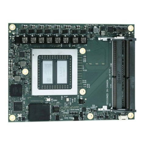
Figure 1: Half-size Card with SMARC interface.......................................................................................................................................10
Figure 2: Top View............................................................................................................................................................................................16
Figure 3: Front View.........................................................................................................................................................................................16
Figure 4: Back View..........................................................................................................................................................................................16
Figure 5: Rear Side from SMARC sxal ........................................................................................................................................................17
Figure 6: Mechanical Drawing from SMARC sxal ..................................................................................................................................17
Figure 7: Heatspreader as cooling solution.............................................................................................................................................18
Figure 8: 3-pin Fan Connector......................................................................................................................................................................21
Figure 9: 6-pin CPLD Connector.................................................................................................................................................................. 22
Figure 10: 314-pin SMARC Connector,.......................................................................................................................................................23

