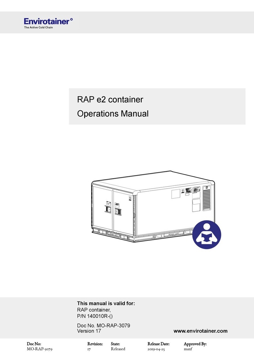
Envirotainer Releye RAP User manual

RAP container,
Model 140020R, P/N 140020R-A-()-()
Doc No. UM-RAP-1002
Version 0
www.envirotainer.com
Releye®RAP
User Manual
Doc No:
UM-RAP-1002
Revision:
0
State:
Released
Release Date:
2021-12-10
Approved By:
hanst

Record of revision
RECORD OF REVISION
VER. NO. REVISION
0 First release
Doc No:
UM-RAP-1002
Revision:
0
State:
Released
Release Date:
2021-12-10
Approved By:
hanst

TABLE OF CONTENTS
1. INTRODUCTION.......................................................................................................................... 1
1.1 Container type..........................................................................................................................1
1.2 Intended use............................................................................................................................1
1.2.1 Operating environment ................................................................................................1
1.3 Manufacturer............................................................................................................................2
1.4 Contact....................................................................................................................................2
1.5 Declaration of conformity ..........................................................................................................2
2. SAFETY......................................................................................................................................... 3
2.1 Symbols ..................................................................................................................................3
2.1.1 Symbols in the manual ................................................................................................3
2.1.2 Symbols on the container.............................................................................................4
2.1.2.1 ODLN sticker...................................................................................................5
3. CONTAINER DESCRIPTION..................................................................................................... 6
3.1 Orientation conventions ............................................................................................................6
3.2 Overview .................................................................................................................................7
3.3 Refrigeration system operation ..................................................................................................9
3.4 Walls .....................................................................................................................................10
3.5 Operating conditions...............................................................................................................10
4. USING THE CONTAINER ........................................................................................................ 11
4.1 Preparing a shipment.............................................................................................................. 11
4.2 Shipping ................................................................................................................................12
4.3 Finishing a shipment...............................................................................................................12
4.4 Operating instructions.............................................................................................................13
4.4.1 Lifting and moving the container .................................................................................13
4.4.1.1 Lift from the sides ..........................................................................................13
→
Doc No:
UM-RAP-1002
Revision:
0
State:
Released
Release Date:
2021-12-10
Approved By:
hanst

4.4.1.2 Lift from the front (door side) ........................................................................... 14
4.4.1.3 Lift from the rear (machine room side) .............................................................14
4.4.1.4 Lift with electric pallet jack ..............................................................................14
4.4.1.5 Use a roller bed system..................................................................................15
4.4.2 Pre-conditioning cargo and container..........................................................................15
4.4.2.1 Pre-condition the cargo ..................................................................................15
4.4.2.2 Pre-condition the container.............................................................................15
4.4.3 Loading cargo...........................................................................................................19
4.4.4 Charging the container ..............................................................................................22
4.4.4.1 Safety precautions .........................................................................................22
4.4.4.2 The charging unit...........................................................................................23
4.4.4.3 Charge the container......................................................................................23
4.4.4.4 Order additional charging adapters .................................................................25
4.4.5 Precautions during shipment......................................................................................26
4.4.6 Storing the container .................................................................................................26
4.4.7 Operating the display unit ..........................................................................................27
4.4.7.1 The display unit .............................................................................................27
4.4.7.2 Wake the display up from sleep mode .............................................................29
4.4.7.3 Set the temperature .......................................................................................30
4.4.7.4 Check the battery level...................................................................................30
4.4.7.5 View and address active alarms and alerts ......................................................31
4.4.7.6 Turn the temperature control off ......................................................................31
4.4.7.7 Disable connectivity .......................................................................................32
4.4.7.8 Lock and unlock the display unit for input ......................................................... 33
5. TROUBLESHOOTING.............................................................................................................. 34
5.1 Information messages ............................................................................................................34
5.2 Alerts.....................................................................................................................................34
→
Doc No:
UM-RAP-1002
Revision:
0
State:
Released
Release Date:
2021-12-10
Approved By:
hanst

5.3 Alarms...................................................................................................................................35
5.4 Hardware...............................................................................................................................36
6. TECHNICAL SPECIFICATION................................................................................................ 38
6.1 Definition of dimensions..........................................................................................................39
Doc No:
UM-RAP-1002
Revision:
0
State:
Released
Release Date:
2021-12-10
Approved By:
hanst

Intentionally left blank
Doc No:
UM-RAP-1002
Revision:
0
State:
Released
Release Date:
2021-12-10
Approved By:
hanst

1. Introduction
1. INTRODUCTION
This manual is intended for shipper, forwarder and airline personnel involved in the operation of the Envirotainer
Releye® RAP container. The manual is published by Envirotainer AB without warranty.
1.1 CONTAINER TYPE
The container is an active Unit Load Device (ULD) according to ETSO-C90d A1, including non-ETSO functions,
primary to keep cargo in a temperature-controlled environment.
The container is a 2A8C designed according to AS36100 and LD-9.
1.2 INTENDED USE
The container is designed for transporting temperature sensitive cargo, and is intended for use in aircraft, trucks
and trains. The container may also be transported by ship when empty or loaded with non temperature sensitive
cargo.
Operating conditions when transporting temperature sensitive cargo are stated in 3.5 Operating conditions.
The container may only be handled and operated in accordance with the instructions given in this manual.
Operational limitations regarding maximum gross weight, ambient temperatures and power requirements stated
in the 6. Technical specification must not be exceeded.
When loaded on an aircraft, or other means of transportation, the container must run on battery power. It must
never be connected to a power outlet inside an aircraft or other means of transportation.
Connectivity:
The container is provided with connectivity equipment for wireless data transmission. This equipment has built
in flight detection in accordance with AC 91.21-1D, sections 10.2 and 10.3. It uses two independent means to
control the RF transmitters and automatically turns off the RF transmitters when the container is airborne.
A manual connectivity switch is also available, to override the automatic flight detection and enable transport on
an aircraft for which the operator has not approved the use of equipment based on automatic flight detection in
accordance with AC 91.21-1D, sections 10.2 and 10.3. Refer to 4.4.7.7 Disable connectivity.
If there are questions about the intended use, refer to 1.4 Contact for contact details.
1.2.1 OPERATING ENVIRONMENT
The container is designed to meet the following environmental conditions:
Maximum altitude (unpressurized) AC power: 3000 m (9842 ft)
Battery power: 4600 m (15 092 ft)
Minimum air pressure 0,506625 bar, corresponding to 15 000 ft at -5°C (23°F) or
equivalent
Maximum relative humidity 95 % for temperatures up to 50 °C (122 °F) decreasing linearly to
85 % at 38 °C (100.4 °F)
Maximum supply voltage fluctuations Up to ±10 % of the nominal voltage
Overvoltage category Category II
Wet location Wet location (outdoor use)
Applicable pollution degree Pollution degree 3
→
1 (40)
Doc No:
UM-RAP-1002
Revision:
0
State:
Released
Release Date:
2021-12-10
Approved By:
hanst

1.3 Manufacturer
Container enclosure ingress
protection code
IP15B
1: Protection from solid objects, such as hands, greater than Ø
50 mm (1.97'') from touch
5: Protection from low pressure water jets from any direction
B: Protection against access with bendable probe, such as a
finger, greater than Ø 12 mm (0.47'') and length less than 80
mm (3.15'') from touch
1.3 MANUFACTURER
The container is manufactured and provided by:
Envirotainer Engineering AB
Staffans väg 2A
SE-192 78 Sollentuna
SWEDEN
1.4 CONTACT
For contact information to our operations centers, refer to www.envirotainer.com.
For questions regarding this manual or the container, send an e-mail to support@envirotainer.com.
For ordering of additional adapters, send an e-mail to logisticspareparts@envirotainer.com. Refer to
4.4.4.4 Order additional charging adapters for ordering details.
1.5 DECLARATION OF CONFORMITY
Declaration of conformity to be inserted when available.
2 (40)
Doc No:
UM-RAP-1002
Revision:
0
State:
Released
Release Date:
2021-12-10
Approved By:
hanst

2. Safety
2. SAFETY
• Read the manual before handling and operating the container.
• Pay attention to warning stickers and texts attached to the container.
• Before closing the doors, make sure that nobody is inside the cargo space.
• Observe normal precautions when handling locks, doors and lids.
• Always follow the "IATA Dangerous Goods Regulations" when loading the container.
2.1 SYMBOLS
2.1.1 SYMBOLS IN THE MANUAL
The following symbols are used in the manual:
WARNING!
Indicates a possible danger that can lead to death or serious injury if necessary measures are not taken.
CAUTION!
Indicates a possible hazard that can lead to injury or material / equipment damage if necessary measures are
not taken.
NOTE!
Practical information or tips on how to perform a procedure.
3 (40)
Doc No:
UM-RAP-1002
Revision:
0
State:
Released
Release Date:
2021-12-10
Approved By:
hanst

2.1.2 Symbols on the container
2.1.2 SYMBOLS ON THE CONTAINER
Fig. 1 Symbols on the container
Table 1 Stickers
Pos Name Pos Name
AIATA-code JSticker “Tare weight”
BSticker “Contact information” KSticker “Center of gravity”
CStickers “Envirotainer” and “Releye®”
(also on roof)
LDocument pouch
DSticker “Seal” MSticker “Place stickers here”
ESticker “Auto - disabled” NSticker “Do not charge inside aircraft”
FManufacturer’s plate OSticker “FAA”
GSticker “Time and temperature sensitive” PSticker “Non-TSO function”
HODLN sticker QSticker “Fork guides”
ISticker “Active ULD”
4 (40)
Doc No:
UM-RAP-1002
Revision:
0
State:
Released
Release Date:
2021-12-10
Approved By:
hanst

2.1.2 Symbols on the container
2.1.2.1 ODLN STICKER
Fig. 2 The ODLN sticker
The container is labeled with an Operational Damage Limits
Notice (ODLN) sticker, in accordance with the IATA labelling
requirements for aircraft containers. The ODLN describes
the acceptable damage limits from an airworthiness
perspective for safe carriage on the aircraft.
Before every lease, the container is inspected against even
stricter criteria than those stated on the ODLN. Therefore,
the container will never exhibit the level of damages as
described on the ODLN when released from an Envirotainer
station.
5 (40)
Doc No:
UM-RAP-1002
Revision:
0
State:
Released
Release Date:
2021-12-10
Approved By:
hanst

3. Container description
3. CONTAINER DESCRIPTION
For information about container dimensions, loading capacity, temperature capacity, power consumption and
battery autonomy, refer to 6. Technical specification.
3.1 ORIENTATION CONVENTIONS
Fig. 3 Schematic view of the container with orientation conventions
6 (40)
Doc No:
UM-RAP-1002
Revision:
0
State:
Released
Release Date:
2021-12-10
Approved By:
hanst

3.2 Overview
3.2 OVERVIEW
Fig. 4 Overview of the container
Table 2 Container features
Pos Name Description
ADisplay unit Used for:
• Setting the cargo temperature set point
• Starting pre-conditioning
• Checking the battery level
• Viewing activated alarms
• Turning the refrigeration system on/off
• Manually disabling the connectivity
BRefrigeration system In the machine room behind the service hatch.
Includes rechargeable battery modules and
mechanical refrigeration modules.
CCharging unit Contains charging cable and adapters.
DFork lift pocket For lifting the container.
EAir distribution panel Contains several air channels for cooled or heated
air.
→
7 (40)
Doc No:
UM-RAP-1002
Revision:
0
State:
Released
Release Date:
2021-12-10
Approved By:
hanst

3.2 Overview
Table 2 Container features (cont'd.)
FStrap with hook For locking the door in opened position.
GStrap For temporarily suspending air cargo straps
during loading.
HTie-down tracks For securing cargo.
ICargo space Contains air distribution panels, temperature
sensors and tie-down tracks.
JReturn air outlet For return air from the cargo space.
KAir inlets Supply the cooled or heated air from the air
distribution panels into the cargo space.
8 (40)
Doc No:
UM-RAP-1002
Revision:
0
State:
Released
Release Date:
2021-12-10
Approved By:
hanst

3.3 Refrigeration system operation
3.3 REFRIGERATION SYSTEM OPERATION
The refrigeration system is powered by internal, rechargeable battery modules, and controlled by a control
module. Sensors in the cargo space walls send signals to the control module, which controls a number of
mechanical refrigeration modules, so that the correct temperature in the cargo space is maintained.
Fig. 5 Schematic view of the internal airflow (example: Releye RLP container)
Temperature-controlled air is circulated from the mechanical refrigeration modules through the air distribution
panels in the ceiling, walls and doors, and into the cargo space. The air travels along the inner floor and re-
enters the refrigeration system through return air outlets in the partition wall at the rear of the cargo space.
To ensure proper air distribution in the cargo space, it is important that the cargo is placed on pallets. Ideally,
cargo should be secured with straps to the tie down tracks in the inner floor.
Fig. 6 Schematic view of the internal-external airflow transition (example: Releye RLP container)
The air inlets on the container sides are used for cooling the modules in the machine room. The return air from
the machine room is discharged through exhaust outlets in the service hatch.
→
9 (40)
Doc No:
UM-RAP-1002
Revision:
0
State:
Released
Release Date:
2021-12-10
Approved By:
hanst

3.4 Walls
The container is fitted with independent subsystems for both redundancy and reliability purposes:
• multiple mechanical refrigeration modules, each containing heater, cooler and fans
• multiple battery modules
This means that even if one mechanical refrigeration module malfunctions during a shipment, the shipment can
be carried out without any loss of temperature performance. Loss of a single battery module will not affect the
container temperature performance, but it will reduce the autonomy time.
3.4 WALLS
Fig. 7 Cross section of the container wall
The walls are composed of three layers:
• Sandwich panel (A)
• Insulation panel (B)
• Air distribution panel (C)
Damages such as scratches to the outer surface (D) of the
sandwich panel does not affect the flight safety properties of
the container. Light damages to the sandwich panel (A)
does not affect the insulation performance of the container.
3.5 OPERATING CONDITIONS
The following conditions must apply in order for the container to work properly when transporting temperature
sensitive cargo:
• The cargo and the container must be pre-conditioned to the temperature set point.
• The container must have sufficient battery power for the intended duration and conditions of the shipment.
• The container must not be exposed to ambient temperatures outside the operational limits. Refer to
6. Technical specification.
For information about the environmental conditions, refer to 1.2.1 Operating environment.
10 (40)
Doc No:
UM-RAP-1002
Revision:
0
State:
Released
Release Date:
2021-12-10
Approved By:
hanst

4. Using the container
4. USING THE CONTAINER
A shipment (B) is defined as all land and air transportation that is required to transfer a loaded container from
the shipper site (A) to the consignee site (C).
Fig. 8 The shipment chain
Chapters 4.1-4.3 contain three separate checklists, listing the actions to be performed when preparing a
shipment, shipping the container, and finishing the shipment. Follow the applicable checklist, as defined below,
to make sure that all necessary measures for a successful shipment are taken. The checklists contain
references to relevant operating instructions.
•Preparing a shipment: Container handling at the shipper site, from receiving the empty container to
handover of the loaded container.
•Shipping: Container handling during land transportation to and from the airport, and at the airport. To be
performed by forwarders and airport personnel.
•Finishing a shipment: Container handling at the consignee site, from receiving the loaded container to
handover of the empty container.
The checklists may be printed out to make sure that they are completed.
4.1 PREPARING A SHIPMENT
Before the shipment, the following must be performed:
□ Pre-condition the cargo. Refer to 4.4.2.1 Pre-condition the cargo.
□ Pre-condition the container. Refer to 4.4.2.2 Pre-condition the container.
□ Confirm (on the display unit) that the container is within the required temperature range. A fixed green
status indicator light indicates that the container is ready.
□ Load and strap the cargo. Refer to 4.4.3 Loading cargo.
□ Confirm that all doors and lids are closed and latched.
□ Check that the battery level is sufficient for the shipment. If not, charge the container. Refer to
4.4.7.4 Check the battery level and 4.4.4 Charging the container.
□ Take action on any active alarms and alerts. Refer to
4.4.7.5 View and address active alarms and alerts.
□ Make sure that the container is not wrapped. Refer to 4.4.5 Precautions during shipment.
□ Make sure that the container is handled in ambient temperatures within the allowed operational limits, and
limit exposure to other temperatures. Refer to 3.5 Operating conditions and 6. Technical specification.
For instructions on lifting and moving the container, refer to 4.4.1 Lifting and moving the container.
11 (40)
Doc No:
UM-RAP-1002
Revision:
0
State:
Released
Release Date:
2021-12-10
Approved By:
hanst

4.2 Shipping
4.2 SHIPPING
During the shipment, the following must be performed:
□ Take action on any active alarms and alerts. Refer to
4.4.7.5 View and address active alarms and alerts.
□ Make sure that the container is not wrapped. Refer to 4.4.5 Precautions during shipment.
□ Make sure that the container is handled in ambient temperatures within the allowed operational limits, and
limit exposure to other temperatures. Refer to 3.5 Operating conditions and 6. Technical specification.
□ If the duration of the shipment exceeds the specified autonomy for the container, or if the shipment is
performed in challenging ambient conditions, consider charging the container whenever it is in a
warehouse. Refer to 4.4.4 Charging the container.
□ Make sure that all doors and lids are closed and latched.
□ Limit the time on the tarmac during aircraft loading (to avoid temperature extremes and direct sunlight).
For instructions on lifting and moving the container, refer to 4.4.1 Lifting and moving the container.
4.3 FINISHING A SHIPMENT
After the shipment, the following must be performed:
□ Take action on any active alarms and alerts. Refer to
4.4.7.5 View and address active alarms and alerts.
□ Unload the cargo.
□ Turn the temperature control off. Refer to 4.4.7.6 Turn the temperature control off.
For instructions on lifting and moving the container, refer to 4.4.1 Lifting and moving the container.
For storage instructions, refer to 4.4.6 Storing the container.
12 (40)
Doc No:
UM-RAP-1002
Revision:
0
State:
Released
Release Date:
2021-12-10
Approved By:
hanst

4.4 Operating instructions
4.4 OPERATING INSTRUCTIONS
4.4.1 LIFTING AND MOVING THE CONTAINER
Fig. 9 Fork lift pockets and tie-down brackets
The container can be lifted using a forklift when empty or loaded. The forklift pocket center to center distance is
852 mm (33.5ʺ) and the forklift pocket width is 255 mm (10.04ʺ).
If the container must be pulled, the pulling device shall be attached to the tie-down brackets (A) on the base.
CAUTION!
Make sure that the charging cable is not connected to a power outlet before moving the container.
CAUTION!
Do not place the container on any electrical cables, such as the charging cables of other containers.
CAUTION!
Do not pull the container by the strap handles when the container is not placed on roller beds, as the strap
handles may come loose.
CAUTION!
Do not drag the container against the ground, as this may cause damage to the container.
4.4.1.1 LIFT FROM THE SIDES
When lifting from the sides, the forklift pockets in the container base shall be used.
• Minimum length of forks when the container is empty: 1600 mm (63ʺ)
• Minimum length of forks when the container is loaded: 1600 mm (63ʺ)
13 (40)
Doc No:
UM-RAP-1002
Revision:
0
State:
Released
Release Date:
2021-12-10
Approved By:
hanst

4.4.1 Lifting and moving the container
4.4.1.2 LIFT FROM THE FRONT (DOOR SIDE)
When lifting from the front, the forklift pockets in the container base shall be used.
CAUTION!
Risk of crush injury! Due to the weight of the refrigeration system at the rear, it is not recommended to lift the
container from the front.
• Minimum length of forks when the container is empty: 2200 mm (86.6'')
• Minimum length of forks when the container is loaded: 2200 mm (86.6'')
4.4.1.3 LIFT FROM THE REAR (MACHINE ROOM SIDE)
When lifting from the rear, the forklift pockets in the container base shall be used.
• Minimum length of forks when the container is empty: 1600 mm (63'')
• Minimum length of forks when the container is loaded: 1600 mm (63'')
4.4.1.4 LIFT WITH ELECTRIC PALLET JACK
When lifting with an electric pallet jack, the pallet jack forks shall be placed underneath the container base and
not inside the forklift pockets.
Fig. 10 How to lift the container with an electric pallet jack (example: Releye RLP container)
→
14 (40)
Doc No:
UM-RAP-1002
Revision:
0
State:
Released
Release Date:
2021-12-10
Approved By:
hanst
This manual suits for next models
1
Table of contents
Other Envirotainer Medical Equipment manuals
Popular Medical Equipment manuals by other brands
laerdal
laerdal SimMan 3G Trauma Quick setup guide
Kodak
Kodak X-Omat M43 PROCESSOR Diagnostics guide
Hologic
Hologic ThinPrep Imager Duo Operator's manual
VIEWRAY
VIEWRAY MRIdian System 4.5 Operator's manual
Care of Sweden
Care of Sweden CuroCell Nova CX13 user manual
icare HOME
icare HOME TA022 Patient guide
