EKKO EOP68 User manual

SPECIFICATION
ORDER PICKER
EOP68

Introduction
In order to meet the needs of the national environmental protection request, To
reduce industrial pollution and improve productivity, we develop new series of
EOP68 Type High level order picker . on the basis of absorption of the advantages
of domestic & overseas battery order picker, they are especially suitable for cargo
loading and unloading, handling, stacking, etc. for food, bank, light textile, station,
port, logistics and other enterprises.
The order picker adopts advanced structures such as EPS steering system, new AC
controller. It is equipped with high-quality motor, traction battery and high-power
pumping station motor. Therefore, it has the characteristics of superior
performance, convenient operation, wide field of view, flexible steering, reliable
braking, good power, low noise, no pollution, and beautiful appearance.
This manual describes the technical parameters of the order picker, working
principle and operation, maintenance, and other aspects. It can help operators use
the order picker more reasonable, make its maximum effect.
It is hoped that Operator strictly abide the regulations and the precautions in this
manual when using the order picker .Carefully use them so that your order picker
can be in the best working condition for long period of time to maximize its
effectiveness. And create better economic benefits.
The Statement
Our company production model EOP68 type high level order picker is a special
motor vehicle used in factory ,tourist attractions ,amusement places which is
specified by “special equipment safety supervision regulations”.

Contents
1.The General Introduction.............................................................................................1
2.Proper usage.....................................................................................................................2
3.Introduction of the product.........................................................................................3
3.1Overview of main components ........................................................................................ 3
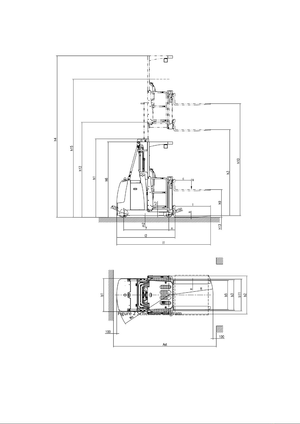
3.2Truck schematic diagram & Model parameters...................................................... 4
3.3Safe operation and warning labels ................................................................................. 7
3.4Name plate ............................................................................................................................. 8
4.Safety Caution...................................................................................................................8
5.Test run,Transportation,Outage............................................................................. 10
5.1Test run .................................................................................................................................10
5.2Lifting & Transportation...................................................................................................10
5.3Outage......................................................................................................................................11
6.Routine Inspection ...................................................................................................... 11
7.The Schematic diagram of Operating Mechanism............................................ 11
8Operating specification............................................................................................... 14
8.1Parking ....................................................................................................................................14
8.2Loading capacity graph.....................................................................................................14
8.3Lifting up/Lowering down ..............................................................................................15
8.4Traveling.................................................................................................................................16
8.5Steering .................................................................................................................................17
8.6Monitor .................................................................................................................................18
8.7Braking ....................................................................................................................................19
8.8Brake structure &Brake Schematic ..............................................................................20
8.9Trouble....................................................................................................................................20
8.10Emergency situations......................................................................................................20
9Changing and Replacement for battery................................................................. 21
9.1Replacement .......................................................................................................................22
9.2Charging ................................................................................................................................23
10.Maintain Introduction .......................................................................................................23

10.1Maintenance list................................................................................................................24
10.2Lubrication point ..............................................................................................................25
10.3Check and refill hydraulic oil .......................................................................................25
10.4Check the electrical fuse.................................................................................................26
10.5 Remove and reinstall the shield.................................................................................26
11.Trouble shooting ..................................................................................................... 27
12.After-sales service..................................................................................................... 28
13.Electrical Schematic diagram.................................................................................... 29
14.Hydraulic Schematic diagram............................................................................... 30

1
1.The General Introduction
EOP68 Type High level order picker uses a battery as the power source and AC
motor as power to drive the truck through gear transmission, The lifting of the
fork is driven by the AC motor hydraulic drive to push the cylinder to lift and lower
the cargo. As the truck Electric motor for Lifting and Driving .Then it has the
characteristics of labor saving, high efficiency, stable cargo operation, simple
operation, safety and reliability, low noise and no pollution.
The device is suitable for Stacking & Handling cargo on firm ,flat floors
The service environment:
a. Altitude does not exceed 3937ft;
b. Indoor room temperature at +5℃to +40℃;
c. When environment temperature at +40℃,the relative humidity can’t over
50%,at low temperature ,allow bigger relative humidity
d. Firm, Flat ground 。
e. It is forbidden to use this car in corrosive environment such as flammable
and explosive or acid base

2
2. Proper use
Please using the High-level order picker according to this specification.
This is a stand on type High level order picker with autonomous control ,
lifting and lowering is controlled by the handle button.
Improper use can cause personal injury or machine damage. Operators or
operating companies need to ensure proper using,
The Truck needs to be used on a firm ,flat ,intact surface and suitable
surface ;the truck is designed for indoor use at room temperature from+5°C to
+40°C
Use under light load without using permanent barriers or pits ,It is
forbidden to operate on the slopes .During Operation ,The goods must be placed
approximately at the center of the truck’s load center
Lifting or Carrying people is strictly prohibited ,If carried goods .The goods
must fall on the lifting point 。
It is prohibited to use this truck on lifting or loading ramps.
The rated capacity is marked on the capacity label or nameplate. And the
operator must pay attention to the warming signs and safety instructions.
Operating lighting must be at least 50LUX
Modification
Any modification that may affect the truck rated capacity, stability or safety
operations must be approved in advance by the Truck’s original manufacturer or
Its authorized Manufacturer or its successor. This includes the effects of changes
such as Braking ,steering ,visibility, and the addition of removable accessories.
After the manufacturer or its successor approves the modification or change ,the
capacity name plate ,Label, identification marks, operation and maintenance
manual must be changed accordingly
Truck damage caused by not following Instruction will lose its warranty.

3
3.Introduce of the product
3.1Overview of main components
Figure 1 main components
1.Driving wheel
2.Cover
3.Battery cover
4.Lifting reinforcement rod
5.Door frame
6.Cockpit
7.Fork
8.Bearing wheel
9.Main frame

4
3.2Truck schematic diagram & Model parameters
Figure 2 Schematic diagram

5
Table 2 EOP68 high level order picker Parameter.
1.2
Model
EOP68
1.3
Drive type
Electric
1.4
Type of operation
Stand on
1.5
Rated load capacity
Q (lbs)
2200
1.6
Load center
c (Inch)
19.68
1.8
Axle center to fork face
x (Inch)
7.56
1.9
Wheelbase
y (Inch)
53.46
weight
2.1
Service weight with battery
lbs
6270
Wheel
3.1
Tire material
PU
3.2
Driving wheel size
Φ×w(Inch)
Φ9.84×5
3.3
Bearing wheel size
Φ×w(Inch)
Φ5.9×3.23
3.4
Balance wheel size
Φ×w(Inch)
-
3.5
No of Driving wheel, Balance
wheel/Bearing wheel(X=Driving wheel
1x,/2
3.6
Track width
b10 (Inch)
-
3.7
Track width
b11 (Inch)
37.8
size
4.2
Lowered mast height
h1(Inch)
93.11
4.4
Lifting height
h3(Inch)
177.16
4.5
Extended mast height
h4 (Inch)
266.65
4.7
Height of overhead guard(cabin)
h6 (Inch)
89.48
4.8
height of seat/stand-on platform
h7 (Inch)
10.67
4.11
Additional lift height
h9 (Inch)
30.71
4.12
total lift height (h3+h9)
h10 (Inch)
208.66
4.14
Platform lifting height
h12(Inch)
187.83
4.15
Lowered fork height
h13 (Inch)
1.97
4.16
Picking height(h12+1300)
h15(Inch)
239.01
4.19
Overall length
l1(Inch)
111.41
4.20
Body Length
l2 (Inch)
69.29
4.21
Overall width
b1/ b2(Inch)
39.37/45.28
4.22
Fork Size
s/e/l(Inch)
1.57/3.93/42.
13
4.25
outside fork width
b5 (Inch)
34.33
4.32
Min. Ground clearance
m2(Inch)
1.97
4.33
Aisle width for pallets 1000*1200
crossways
Ast (Inch)
122.24
4.34
Aisle width with pallet 800 x 1200 along
forks
Ast (Inch)
126.77

6
4.35
Min. Turning radius
Wa (Inch)
61.81
Perfor
mance
5.1
Travel speed, laden/unladen
(km/h)
6.0/5.8
5.2
Lifting speed, with/without load(cabin)
(mm/s)
140/150
5.2
Lifting speed, with/without load(Fork)
(mm/s)
130/140
5.3
Lowering speed, with/without
load(cabin)
(mm/s)
240/250
5.3
Lowering speed, with/without
load(Fork)
(mm/s)
130/95
5.8
Maximum climbing ability, with/without
load
(%)
3/6
5.10
Brake Type
Electromagnet
ic
Motor
6.1
Drive Motor
(kW)
3.0
6.2
Lift Motor
(kW)
5.5
6.3
Battery according to DIN 43531/35/36
A,B,C,no
no
6.4
Battery voltage/rated capacity
(V/Ah)
24/280
6.5
Battery weight (± 5%)
(lbs)
600
Other
8.1
Type of drive control
AC
8.4
Noise level at operator‘s ear
(dB(A))
75

7
3.3Safe operation and warning labels
1.Name plate 2.Load capacity chart 3Read the manual label 4.Wear safety
rope sticker 5No hitchhiking 6.It is forbidden to lean out of the car 7.Hook
sticker 8. It is forbidden to stand on /off the fork 9.Do not put hands in the
car 10.Watch your hands 11.warning label 12.Be careful with electricity
13.Emergency discharge
Figure 3 label diagram
述

8
3.4Nameplate
Figure 4 Nameplate
4.Safety Caution
Please don’t
• When travel outdoor, The stacking operation makes the lifting height of
the cargo higher than the lifting point
• Place the foot or hand under or into the lifting mechanism
• Allow Non-Operators to stand in front of or behind the truck during
moving or lifting / lowering
• Overload
• Put your foot on the front of the wheel may cause injury
• Stick your body out of the cockpit during lifting
• Push and pull cargo
• Use the car on the slope
• Use the car without Shielding panel
• Side load or tail load ,The cargo must be evenly distributed on the fork
• Use this car to load unstable ,unbalanced cargo
!

9
• Use this car without the manufacturer’s written consent
Observing different ground condition during driving .The cargo may fall down, or the
car may lose control ,Please check the loading situation frequently, If the cargo becomes
unstable .Stop the operation of the truck immediately . When the cargo slide or slide off
the truck, Stop the car by pressing emergency stop switch .Please refer to Chapter 6 for
any truck Trouble .Maintain according to regular inspection. The forklift is not waterproof,
Please use it in dry environment. Continuous operation for a long time may damage the
power box ,please stop operating when Hydraulic oil temperature is too high .
• The operator should put on safety shoes when operating the forklift
• The car is suitable for indoor use in temperature from +5°Cto 40°C
• Operating lighting must be at least 50LUX
• Don’t use the car on the slope
• The uplifted cargo will become unstable because of wind .Don’t lift the
cargo in windy condition
• In order to prevent sudden movement of the car when the car is not
operated (such as caused by others),turn off the car power and remove the
key when not operating
!

10
5.Test run, Transportation, Outage
5.1Test run
Table 3 test data
Model
EOP68
Packing weight(lbs)
6270
Lifting height(Inch)
177.16
Size(Inch)
113*49.21*98.43
After receiving our new forklift or when it needs to be retest please with process
with following steps before (the first )operation of the forklift :
• Check if all parts are included .and there is no damage
• Battery installation and charging (refer to Chapter 9)
• Carry out daily inspection and machine function inspection
5.2Lifting & Transportation
Remove the cargo during transportation ,Lowered the
fork to the lowest position and according to Figure 5 Safety
fixed the car with special lifting equipment
Lifting
Use Special Crane and lifting equipment
Don’t stand under shaking cargo
Don’t enter the dangerous area when rising
Parking the truck safely,and and fasten the car body
Lifting the truck to the destination ,Before Moving lifting equipment please safety
Fixed the car ,
The rope point can referred to figure 5
Transportation
The Truck should be firmly fixed on the truck during transportation
Lowered fork and parking the truck safety
As figure 6 shows Use the special binding belt to
!
Fig 5 Lifting Point

11
fix the tow big ribs of the car .And fixed other
side on the carrier
5.3Outage
When Storage remove the cargo and lowered the fork to lowest position.
Grease all lubrication points mentioned in this manual (check regularly)to prevent
rust and dust. Remove the battery and check the truck to ensure no extrusion
during storage.
When the car finally out of service ,send the car to designated recycling
company .According to regulations , Oil, Batteries and electronic components must
be recycled .
6.Routine Inspection
This Chapter Describes check the car before using
Routine inspection can effectively find out the defect or error of this car, The
following points should be checked before operation.
Remove the cargo ,Lowered the fork. Please don’t use the car if there is any
Problem.
• Check for scratches ,Deformation .or Cracks
• Check if the cylinder leaks of oil
• check running condition of the car
• Check if the chain or roller damage or corrosion
• Check if the wheels can move smoothly
• Press the emergency stop button to check the emergency brake function
• Check the Buzzer
• Check whether the display is displayed normally
• Check that all bolts and nuts are tightened
• Check the function of Key switch
• Check the speed limit switch
Fig6 Fixed Point
!

12
• Visually Check for any damaged tube or wires
• If the car with Protective barrier .Check for damage and correct installation.
7.The Schematic diagram of Operating Mechanism
Fig 7 Operating console Fig 8 Key Switch
Figure 7.1 the steering wheel, which controls the steering of the truck by
rotating the steering wheel.
Figure 7.2 is emergency lowering button, When 7.4(as figure shows) lifting &
lowering joystick fails, Press the emergency lowering button to safety lower the
cockpit to the bottom
Firgue7.3 is Curtis instrument, displaying vehicle information.
Figure 7.4 is lifting & lowering joystick , which is used to control the lifting and
lowering of the mast and the cockpit.
Figure 7.5 is Emergency stop switch
Figure 7.6 is Key switch ,Control truck power connection and disconnection
Figure 7.7 Accelerator , Used to control the forward and backward of the truck,
and control the driving speed by controlling the degree of rotation
Figure 7.8,Horn button
Figure 7.9 Headlight switch
Figure 7.10 Waring light switch

13
Fig 9 Operation switch
Figure 9.1 shows the lifting & lowering switch, used to control the lifting and
lowering of the fork.
Figure 9.2 shows the forward and backward buttons, which are used to fine-tune
the position of the truck so that the truck can pick up goods in a suitable position.
Figure 9.3 shows the foot switch. The lifting ,lowering and driving of the truck
must be carried out when the foot switch is depressed.
8.Operating specification
Please follow the warning and safety instructions before operating the car
(see as chapter 3)
Please Ensure that cargo or other equipment will not lead to poor visibility
before operating the car
Ensure cargo level and stable placed .And conduct daily inspection .Insert
the key into the key Switch(Figure 8),Turn the key clockwise to “ON”
position. Before finally inserting the key switch (Figure 8 ),The emergency
stop switch must be carefully pulled up.Press the horn button(as figure7 .8)
to start the buzzer
8.1Parking
Pls Don’t Park on the ramp
The car is equipped with an electromagnetic error protection Parking and
Parking brake
!
!

14
During driving, you can brake by releasing the accelerator or the foot switch.
Please always lower the forks completely and drive the car to a safe area.Turn
the key counterclockwise to the OFF position and pull out the key
8.2Loading capacity Graph
Do not overload, only increase the load capacity allowed by the load
capacity graph
The loading capacity Graph shows a given load center c [Inch] and a car with
horizontal load ,the maximum load capacity Q [lbs.]In the corresponding lifting
height of the truck H [Inch],The white markings on the frame indicate the range
of lift that can be achieved .For example, a cargo's center of gravity distance c is
15.75Inch, the maximum lifting height H is 177.16Inch, and the maximum load
capacity Q is 1540lbs
Figure 10 Loading capacity graph
8.3Lifting up & lowering down
Step on the foot switch, then pull-down and lock the guardrails on both sides of
the cockpit and control the mast main lifting and lowering by controlling the
lifting & lowering joystick A rotate to B ( as figure shows ).

15
Figure 11 Door frame main lifting Figure 12 the lifting & lowering joystick
Use lift switch(Figure 9.1 shows) to control the rising and falling of the fork
attached.
Figure 13 Fork lifting
8.4Traveling
Only drive on the slope when the cargo are facing up
Don’t drive on the slope in excess the specified specifications .
Only can driving when the fork falls to the lifting point (<11.81Inch)

16
⚫Turn the inserted key to the "on" position to start the Truck
⚫While depressing the foot switch, turn the accelerator button to the F
direction to make the truck drive in the direction of ‘Fw’or ‘Bw’.
Release the accelerator to return to the '0' position or release the foot
switch to stop the truck
⚫By carefully turning the button (Figure 7.7) to control the driving speed
until the desired speed is reached.
⚫Drive the vehicle carefully to the destination. Observe the road surface
and adjust the driving speed through the accelerator.
Figure 14.Operation diagram
8.5Steering
The truck is equipped with a power steering system, so be careful when
operating.
Steering the truck by turning the steering wheel in the N direction or S direction
Table of contents
Other EKKO Forklift manuals

EKKO
EKKO EB13E User manual

EKKO
EKKO EK18A-189LI Service manual

EKKO
EKKO EK18RF User manual

EKKO
EKKO ES40E Operating manual

EKKO
EKKO EP20LI Series User manual

EKKO
EKKO EK20R User manual

EKKO
EKKO EP30A User manual

EKKO
EKKO EPE20LI Series User manual

EKKO
EKKO EK18A User manual

EKKO
EKKO EK20LI Series User manual