EP Equipment LIST JX0 User manual

Service Manual
JX0
Task Support Vehicle
Service Manual
Task Support Vehicle
JX0

Release Date Version No. Changes (Serial number)
2019-07-03 SM-1600 07.19 Serial number V1
This manual applies to:
Model Specications
JX0 3000kg Capacity
Some sections of the manual only involve certain model, please refer to the manual
according to the actual conguration of the vehicle.
* If there are any changes, revised version will be published once every 12 months;
if there is no change, please follow the most recent version.
* Please refer to the corresponding version of the service manual against the purchase time
of your vehicle.
* If you need the latest versions of the manual, please contact our service department or
dealer to obtain.

EP Equipment Co., Ltd.
EP Industrial Park, Xiaquan Village,
Dipu Town, Anji County, Zhejiang Province
www.ep-zl.com
Safety signs and instructions:
Please strictly adhere to these safety instructions to avoid personal injury.
Please pay attention to the important safety instructions.
Instructions.
FOREWORD
This Service Manual can help readers learn more about the truck system components,
maintenance and troubleshooting, and other related information. The operation and
maintenance personnel must read this Manual carefully before using the product. And when
vehicle is in use, be sure to follow the complete operation and maintenance information in
this Manual for vehicle maintenance.
Before using, please check if the pages of the Manual are clear and complete, so as not
to aect your normal use because of incomplete information. If the contents of the Manual
have been illegible or damaged, which may aect reading, please contact our company or
dealer for replacement.
With the constant update and improvement of our products, the equipment you are using
may be slightly dierent from what has been described in this Manual, therefore, we must
reserve the right to modify the appearance, conguration and technical specications. If you
have any questions, please contact our sales department or dealer.
i
Copyright
Copyright of Service Manual belongs to
EP Equipment Co., Ltd.
REV. SM-1600 07.19

REV. 07/2019
TABLE OF CONTENTS
TABLE OF CONTENTS
1. INFORMATION & SPECIFICATIONS..............................1
1.1 After-sales Service Platform .........................................3
1.2 Introduction...................................................................4
1.3 Common Tools..............................................................6
1.4 General Tightening Torques .........................................7
2. MAINTENANCE............................................................. 10
2.1 Overview..................................................................... 12
2.2 Maintenance............................................................... 13
2.2.1 Cleaning ........................................................................13
2.2.2 Inspection ......................................................................13
2.2.3 Lubrication.....................................................................18
3. STRUCTURE & FUNCTIONS........................................ 22
3.1 Structure & Functions................................................. 23
3.1.1 Travel Switch .................................................................23
3.1.2 Emergency Stop Switch ................................................23
3.1.3 Key Switch.....................................................................23
3.1.4 Horn Button ...................................................................23
3.1.5 Storage Table Lowering Switch .....................................24
3.1.6 Storage Table Lifting Switch ..........................................24
3.1.7 Charge Gauge...............................................................24
3.1.8 Horn...............................................................................24
3.1.9 Tilt Buzzer (optional)......................................................25
3.1.10 Tilt Buzzer (optional)....................................................25
3.1.11 Door Safety Switch ......................................................25
3.1.12 Platform Lifting Switch.................................................25
3.1.13 Slack Chain Switch......................................................26
3.1.14 Lifting Limit Switch.......................................................26
3.1.15 Speed Reduction Switch .............................................26
3.1.16 Main Contactor ............................................................26
3.1.17 DUALPMX&HP Controller (Traction Controller) 27
3.1.18 EPS-AC0 Controller ....................................................27
3.1.19 Fuse ............................................................................27
3.1.20 Relay ...........................................................................27
3.1.21 Pump Motor.................................................................28
3.1.22 Gear Pump ..................................................................28
3.1.23 AUX pump motor .........................................................28
3.1.24 Solenoid Valve / Manual Pressure Relief Valve...........28
3.1.25 Accumulator.................................................................29
3.1.26 Deadman Switch .........................................................29
SECTION PAGE
1-6

REV. 07/2019
TABLE OF CONTENTS
3.1.27 Stepper Motor..............................................................29
3.1.28 Flash light ....................................................................30
3.1.29 Blue light......................................................................30
3.1.30 Pressure-sensitive switch............................................30
3.1.31 Can Tiller .....................................................................31
3.1.32 Enable swtich ..............................................................31
3.1.33 Platform Lowering Switch............................................31
4. CHASSIS SYSTEM........................................................ 32
4.1 Load Wheel ................................................................ 34
4.1.1 Removal and Installation ...............................................34
4.1.2 Faults and Causes.........................................................34
4.2 Caster......................................................................... 35
4.2.1 Removal and Installation ...............................................35
4.3 Cover.......................................................................... 35
4.3.1 Removal and Installation ...............................................36
5. DRIVE SYSTEM............................................................. 37
5.1 Drive Assembly........................................................... 40
5.1.1 Removal and Installation ...............................................40
5.1.2 Faults and Causes.........................................................40
5.2 Electromagnetic Brakes.............................................. 41
5.2.1 Removal and Installation ...............................................41
5.2.2 Faults and Causes.........................................................42
5.2.3 Checking and Testing ....................................................42
5.2.4 Control Circuit Troubleshooting .....................................43
5.3 Drive Wheel................................................................ 44
5.3.1 Removal and Installation ...............................................44
5.3.2 Faults and Causes.........................................................44
5.4 Drive Motor................................................................. 45
5.4.1 Removal and Installation ...............................................45
5.4.2 Faults and Causes.........................................................45
5.4.3 Checking and Testing ....................................................46
5.5 Speed Encoder........................................................... 46
5.5.1 Removal and Installation ...............................................46
5.5.2 Faults and Causes.........................................................47
5.5.3 Checking and Testing ....................................................47
5.5.4 Control Circuit Troubleshooting .....................................47
5.6 Gearbox...................................................................... 48
5.6.1 Removal and Installation ...............................................48
5.6.2 Faults and Causes.........................................................48
5.7 Proximity Switch ......................................................... 48
2-6
SECTION PAGE

REV. 07/2019
TABLE OF CONTENTS
TABLE OF CONTENTS
5.8 Steering Motor and Chain........................................... 51
5.8.1 Removal and Installation ...............................................51
5.8.2 Faults and Causes.........................................................51
5.8.3 Checking and Testing ....................................................52
5.8.4 Control Circuit Troubleshooting .....................................52
5.9 Speed Encoder........................................................... 53
5.9.1 Removal and Installation ...............................................53
5.9.2 Faults and Causes.........................................................53
5.9.3 Checking and Testing ....................................................53
5.9.4 Control Circuit Troubleshooting .....................................54
6. OPERATING SYSTEM................................................... 55
6.1 Left Control Assembly................................................. 57
6.2 Right Control Assembly .............................................. 57
6.3 Button Switch.............................................................. 58
6.3.1 Removal and Installation ...............................................58
6.3.2 Faults and Causes.........................................................58
6.3.3 Checking and Testing ....................................................58
6.3.4 Control Circuit Troubleshooting .....................................59
6.4 Travel Switch .............................................................. 62
6.4.1 Removal and Installation ...............................................62
6.4.2 Faults and Causes.........................................................62
6.4.3 Checking and Testing ....................................................62
6.4.4 Control Circuit Troubleshooting .....................................62
6.5 Proximity Switch ......................................................... 63
6.5.1 Removal and Installation ...............................................63
6.5.2 Faults and Causes.........................................................63
6.5.3 Checking and Testing ........................................................63
6.5.4 Control Circuit Troubleshooting .....................................63
6.6 Stepper Motor............................................................. 65
6.6.1 Removal and Installation ...............................................65
6.6.2 Faults and Causes.........................................................65
6.6.3 Checking and Testing ....................................................65
6.6.4 Control Circuit Troubleshooting .....................................65
6.7 Key Switch.................................................................. 66
6.7.1 Removal and Installation ...............................................66
6.7.2 Faults and Causes.........................................................66
6.7.3 Checking and Testing ....................................................66
6.7.4 Control Circuit Troubleshooting .....................................66
SECTION PAGE

REV. 07/2019
TABLE OF CONTENTS
3-6
TABLE OF CONTENTS
6.8 Emergency Stop Switch ............................................. 67
6.8.1 Removal and Installation ...............................................67
6.8.2 Faults and Causes.........................................................67
6.8.3 Checking and Testing ....................................................67
6.8.4 Control Circuit Troubleshooting .....................................67
6.9 Charge Gauge............................................................ 68
6.9.1 Removal and Installation ...................................................68
6.9.2 Faults and Causes.........................................................68
6.9.3 Checking and Testing ....................................................68
6.9.4 Control Circuit Troubleshooting .....................................69
7. HYDRAULIC SYSTEM................................................... 70
7.1 Overview..................................................................... 72
7.1.1 Hydraulic Schematic Diagram ......................................73
7.2 Pump and Motor Assembly......................................... 74
7.2.1 Removal and Installation ...............................................74
7.2.2 Component....................................................................74
7.3 Pump Motor................................................................ 75
7.3.1 Removal and Installation ...............................................75
7.3.2 Faults and Causes.........................................................75
7.3.3 Checking and Testing ....................................................76
7.3.4 Control Circuit Troubleshooting .....................................76
7.4 AUX Pump Motor........................................................ 77
7.4.1 Removal and Installation ...............................................77
7.4.2 Faults and Causes.........................................................77
7.4.3 Checking and Testing ....................................................78
7.4.4 Control Circuit Troubleshooting .....................................78
7.5 Solenoid Valve ........................................................... 79
7.5.1 Faults and Causes.........................................................79
7.5.2 Checking and Testing ....................................................79
7.5.3 Control Circuit Troubleshooting .....................................80
7.6 Reach Cylinder........................................................... 81
7.6.1 Cylinder Removal Precautions ......................................81
7.6.2 Cylinder Installation Precautions ...................................82
7.7 Accumulator ............................................................... 83
7.7.1 Removal and Installation ...............................................83
7.7.2 Faults and Causes.........................................................83
7.8 Hydraulic Troubleshooting .......................................... 84
7.9 Hydraulic Symbol........................................................ 85

REV. 07/2019
TABLE OF CONTENTS
5.7.1 Removal and Installation ...............................................48
5.7.2 Faults and Causes.........................................................49
5.7.3 Checking and Testing ....................................................49
5.7.4 Control Circuit Troubleshooting .....................................50
8. ELECTRICAL SYSTEM ............................................... 86
8.1 Controller.................................................................... 88
8.1.1 Removal and Installation ...............................................89
8.1.2 Controller Interface Function .........................................90
8.2 Fuse............................................................................ 98
8.2.1 Location of Fuses ..........................................................98
8.2.2 Checking and Testing ....................................................99
8.3 Main Contactor ......................................................... 100
8.3.1 Removal and Installation .............................................100
8.3.2 Faults and Causes.......................................................100
8.3.3 Checking and Testing ..................................................101
8.3.4 Control Circuit Troubleshooting ...................................101
8.4 Limit Switch .............................................................. 102
8.4.1 Removal and Installation .............................................102
8.4.2 Faults and Causes.......................................................103
8.4.3 Checking and Testing ..................................................104
8.4.4 Control Circuit Troubleshooting ...................................104
8.5 Deadman Switch ...................................................... 106
8.5.1 Removal and Installation .............................................107
8.5.2 Faults and Causes.......................................................107
8.5.3 Checking and Testing ..................................................108
8.5.4 Control Circuit Troubleshooting ...................................108
8.6 Tilt Switch ................................................................. 109
8.6.1 Removal and Installation .............................................109
8.6.2 Faults and Causes.......................................................109
8.6.3 Checking and Testing ..................................................109
8.6.4 Control Circuit Troubleshooting ...................................109
8.7 Blue Light.................................................................. 110
8.7.1 Removal and Installation ............................................. 110
8.7.2 Faults and Causes....................................................... 110
8.7.3 Checking and Testing .................................................. 110
8.7.4 Control Circuit Troubleshooting ................................... 110
8.8 Flash Light.................................................................111
8.8.1 Removal and Installation ............................................. 111
8.8.2 Faults and Causes....................................................... 111
8.8.3 Checking and Testing .................................................. 111
8.8.4 Control Circuit Troubleshooting ................................... 111
4-6
TABLE OF CONTENTS
SECTION PAGE

REV. 07/2019
TABLE OF CONTENTS
8.9 Pressure-sensitive switch......................................... 112
8.9.1 Removal and Installation ............................................. 112
8.9.2 Faults and Causes....................................................... 112
8.9.3 Checking and Testing .................................................. 112
8.9.4 Control Circuit Troubleshooting ................................... 112
8.10 Button switch ............................................................ 113
8.10.1 Removal and Installation ........................................... 113
8.10.2 Faults and Causes..................................................... 113
8.10.3 Checking and Testing ................................................ 114
8.10.4 Control Circuit Troubleshooting ................................. 114
8.11 LED Charging Indicator ........................................... 116
8.11.1 Removal and Installation ........................................... 116
8.11.2 Faults and Causes..................................................... 116
8.11.3 Checking and Testing ................................................ 116
8.11.4 Control Circuit Troubleshooting ................................. 116
8.12 TESTER Menu ........................................................ 118
8.13-A Handheld Unit (Optional)...................................... 125
8.13.1 Handheld Unit Connection................................... 125
8.13.2 Handheld Unit Menu Options .............................. 125
8.13-B Handheld Unit (Optional) ..................................... 127
8.13.1 Fault Detection .................................................... 127
8.13.2 Testing Truck Operation....................................... 127
8.13.3 Settings and Adjustments ........................................ 128
8.13.4 Adjustments ........................................................... 128
8.13.5 Parameter Change ................................................. 129
8.14 Controller Error Message ........................................ 130
8.14.1 Traction Controller ............................................... 130
8.14.2 Steering Controller (EPS-ACO)........................... 148
8.15 Cable Wiring Diagrams............................................ 157
8.16 Electrical Schematic Diagrams................................ 158
8.17 Wiring Harness and Connectors.............................. 160
9. TROUBLESHOOTING................................................. 162
9.1 Troubleshooting Solutions of Common Faults.......... 165
APPENDIX ....................................................................... 169
B3 Lithium Battery.......................................................... 189
B3-1 Safety and Warnings................................................ 189
B3-2 Use of Battery ........................................................ 190
5-6
TABLE OF CONTENTS
SECTION PAGE

REV. 07/2019
TABLE OF CONTENTS
A1-1.1 Chain 1 Replacement ................................................173
A1-1.2 Chain 2 Replacement.................................................173
A1-2.1 Drag Chain Replacement...........................................173
A1-1.2.1 Left Drag Chain Replacement...............................175
A1-1.2.2 Left Drag Chain Replacement...............................175
A1-1.2.3 Left Drag Chain Replacement...............................175
A1-1.2.4 Left Drag Chain Replacement...............................175
A1-1.2.5 Left Drag Chain Replacement...............................175
A1-3 Cylinder.................................................................. 177
A1-3.1 Cylinder Removal......................................................177
A1-3.2 Cylinder Maintenance ...............................................178
A1-3.3 Cylinder Installation...................................................178
B SERVICE MANUAL - BATTERY................................. 179
B1 Lead-acid Battery...................................................... 181
B1-1 Safety and Warnings.............................................. 181
B1-2 Use of Battery ........................................................ 181
B1-2.1 Pre-use Checks ........................................................181
B1-2.2 Discharging...............................................................181
B1-2.3 Charging ...................................................................182
B1-2.4 Temperature..............................................................182
B1-3 Maintenance & Care ............................................. 182
B1-3.1 Daily Maintenance ....................................................182
B1-3.2 Weekly Maintenance.................................................182
B1-3.3 Monthly Maintenance................................................183
B1-3.4 Care ..............................................................................183
B1-4 Storage .................................................................. 184
B1-5 Troubleshooting ....................................................... 184
B2 Maintenance-free Battery......................................... 187
B2-1 Safety and Warnings.............................................. 187
B2-2 Use of Battery .......................................................... 187
B2-2.1 Pre-use Checks ........................................................187
B2-2.2 Discharging...............................................................187
B2-2.3 Charging ...................................................................188
B2-3 Maintenance & Care .............................................. 188
TABLE OF CONTENTS
SECTION PAGE
6-6

REV. 07/2019
TABLE OF CONTENTS
B3-2.1 Pre-use Checks ........................................................190
B2-2.2 Discharging...............................................................190
B2-2.3 Charging .......................................................................190
B3-3 Maintenance & Care ................................................ 191
B3-4 Common problems and solutions ............................ 192
C SCHEDULE ................................................................. 192
7-6
TABLE OF CONTENTS
SECTION PAGE

SAFETY WARNING
For your own safety and that of others, please observe the following safety instructions:
Thorough and normative maintenance is one of the most important prerequisites to ensure
stable and reliable operation of truck. Neglecting regular maintenance could easily lead
to the truck malfunction and failure, and potential threats to staff and operational safety.
Therefore, there must be adequate maintenance equipment, professional maintenance
personnel and a comprehensive maintenance plan in place.
Please perform the maintenance and inspections according to the following provisions:
To strictly enforce the truck maintenance, lubrication and inspection plans.
Truck maintenance, lubrication and inspection personnel must be approved by accredited
certication or evaluation agency.
The following operations shall be performed before you leave the truck:
- No parking on slopes.
- Fully lower the forks.
- Cut o the power supply.
- Turn the switch lock to “STOP” and remove the key.
Prior to truck maintenance:
- Raise the drive wheel o the ground, or cut o the power supply connection.
- Use wooden wedges or other eective xtures.
- When performing maintenance underneath the vehicle, make sure that the lifting device
or jack leg is secure.
- Park your vehicle in a safe and secure area.
Never use an open ame to check level of electrolyte, other oils or uids for leaks.
Keep the parking lot clean, well-ventilated and dry.
Regular checks and maintenance should be conducted to braking, steering, control, warning
and safety devices to keep them in good condition.
All nameplates and safety signs on the truck should be cleaned regularly to make them
clearly visible.
Regular checks and maintenance should be conducted to all the devices of lifting system to
ensure them to be safe for use.
The hydraulic system should be checked regularly based on usage. Hydraulic cylinders,
hydraulic valves and other hydraulic components should be ensured to be without leakage.
Regular checks and maintenance should be conducted to batteries, motors, controllers,
limit switches, protective devices, wires and connectors, and so on. Please pay particular
attention to the electrical insulation.
Park the truck in a clean environment to minimize the risk of re.
Without the permission of the manufacturer, users are not allowed to change or increase
the capacity of the truck. After having been changed under permission, the nameplates and
safety signs on the truck should also be changed accordingly.
1.
2.
3.
4.
5.
6.
7.
8.
9.
10.
11.
12.
13.
1
1
1. INFORMATION & SPECIFICATIONS

2
NOTE:
3
REV. 07/2019
INFORMATION & SPECIFICATIONS
1
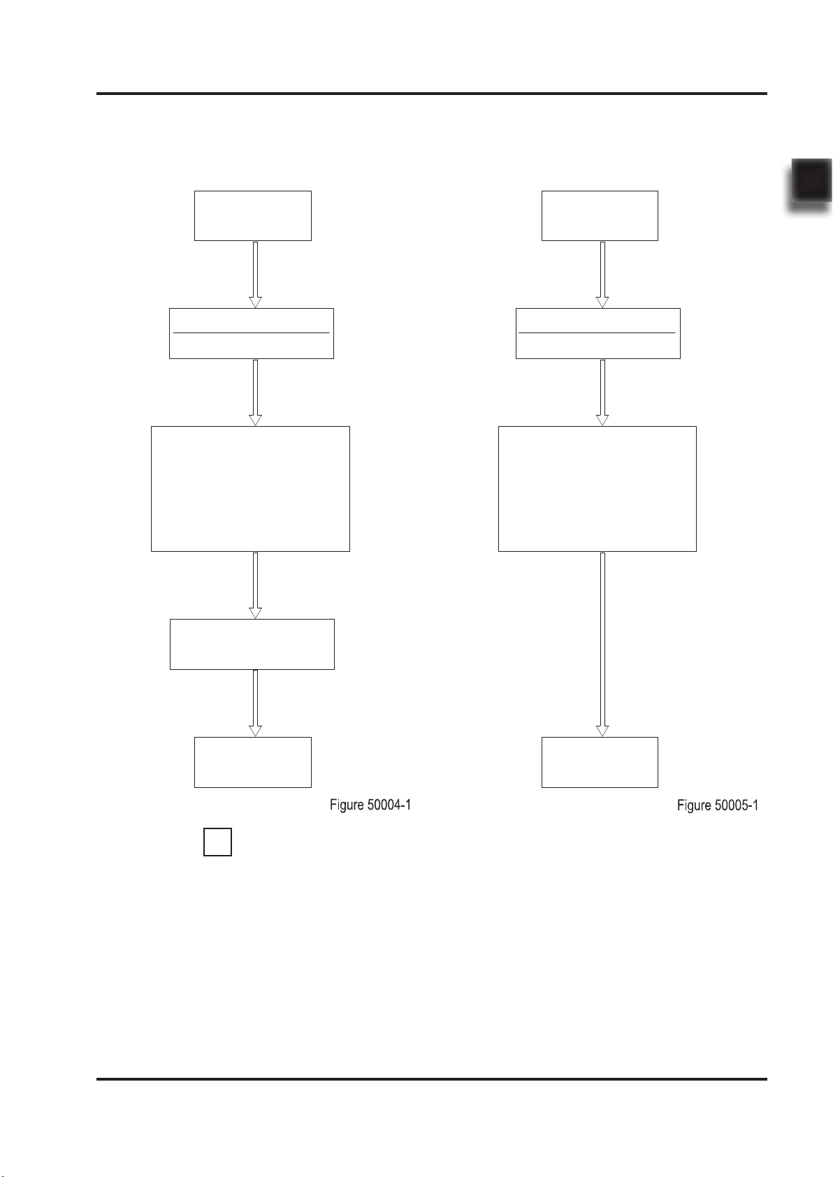
1.1 After-sales Service Platform
Claims/Replacement Parts Service Platform:
In order to provide you with a fast and ecient
after-sales service, when you claim / order spare
parts or after-sales service upon maintenance,
please provide accurate truck model, vehicle
body serial number and part number.
After-sales Maintenance Service Platform:
Customer
Customer
Components
Warehouse
Customer service to input
into After-sales System.
After-sale Engineer to
call back to confirm the
accuracy of the information
about the components.
Shipped within
24 hours
Claim Form
Customer service to input
into After-sales System.
After-sale Engineer to call
back to confirm about the
specic fault information.
Within two business
days after the mainten-
ance, customer service
will call back and close
the claim.
Maintenance service
specialist will provide
on-site service at the
appointed time.
iNOTE
Customer
Claim Form
Customer
REV. 07/2019
INFORMATION & SPECIFICATIONS
1
4
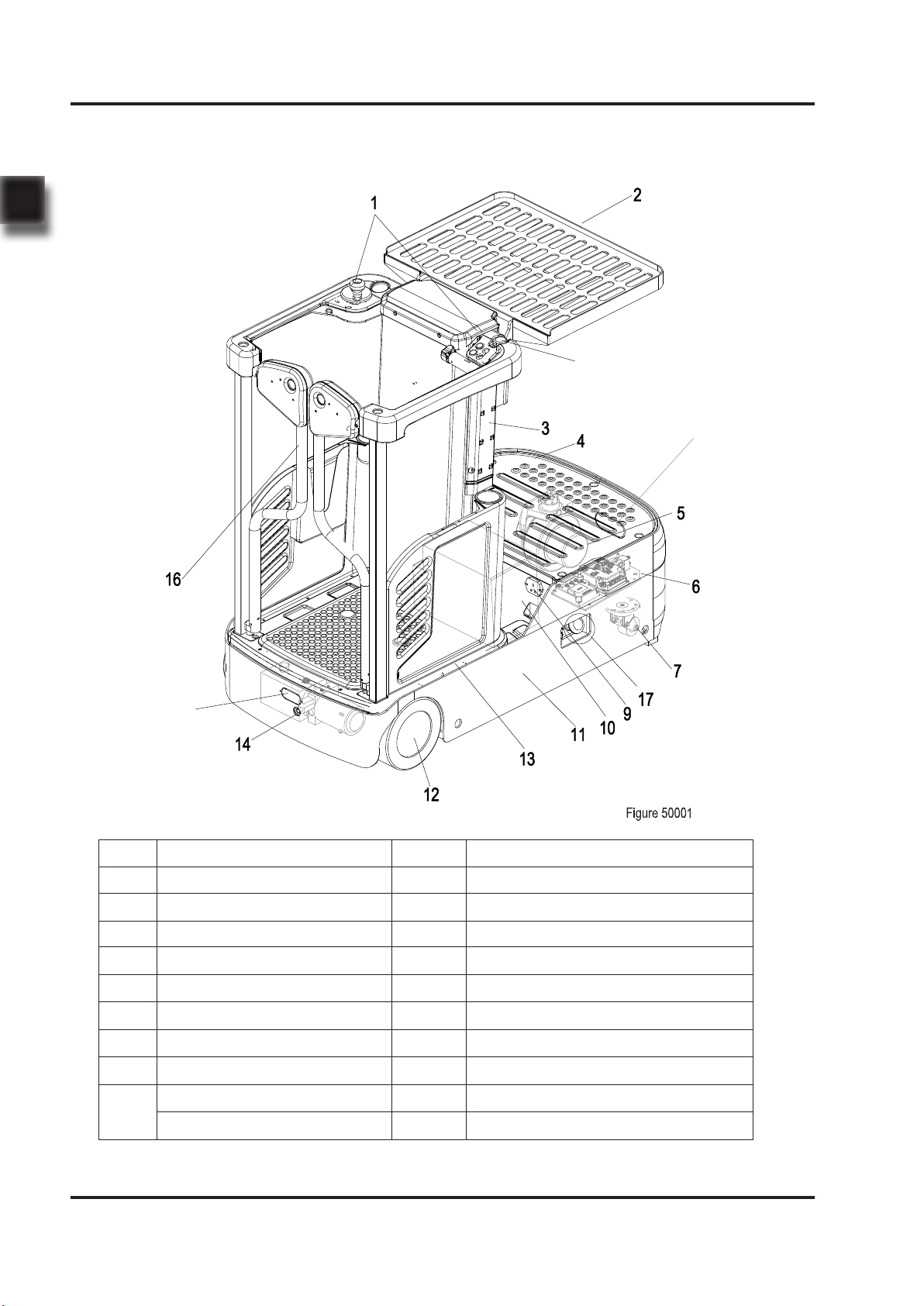
1.2 Introduction
15
18
8
1 Control panel 11 Chassis
2 Storage table 12 Load wheels
3 Lift mast 13 Lift platform
4 Additional storage table 14 Hydraulic pump
5 Drive wheel 15 Flash light
6 Controller 16 Safety Gates
7 Caster 17 Emergency operation area
8 Emergency stop switch 18 Blue light
9 Charger socket
10 Battery
Lithium Battery
5
REV. 07/2019
INFORMATION & SPECIFICATIONS
1
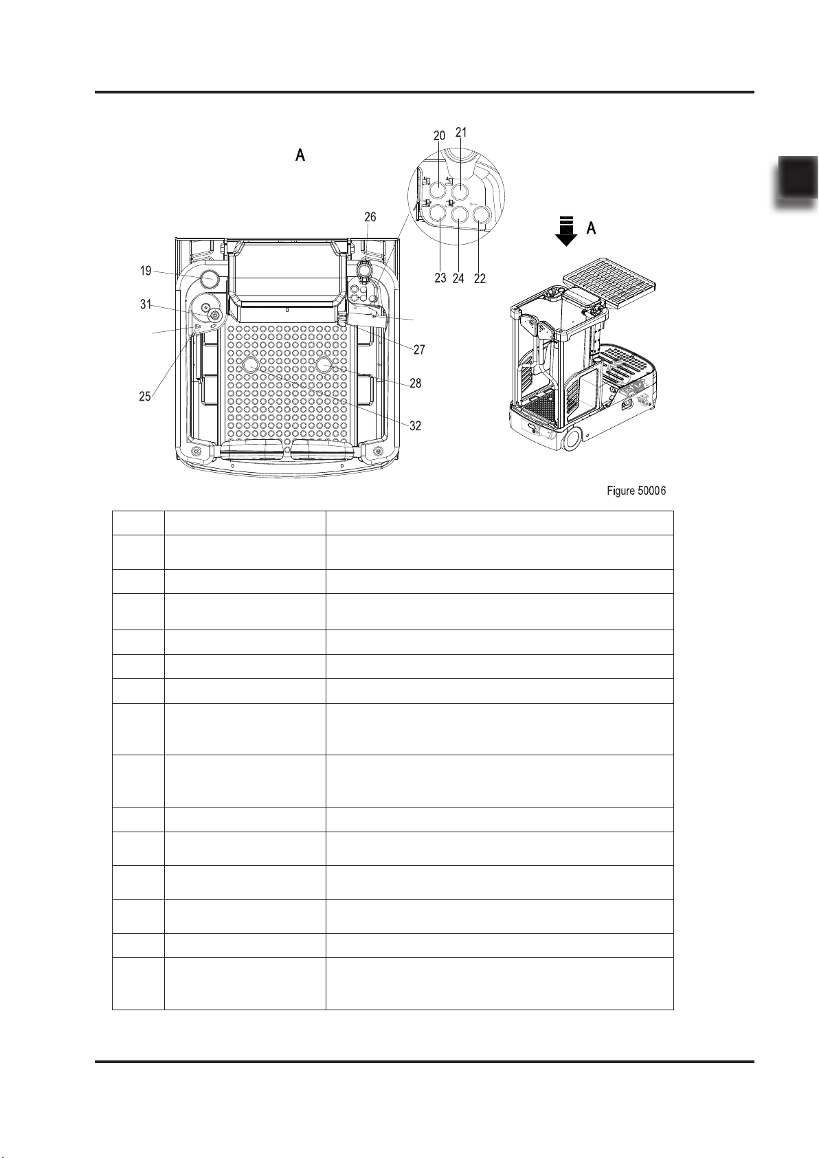
Item Control / Display Function
19 Display unit Operating information and warning message
display.
20 "Lifting" button Lift the storage table.
21 "Lowering" button Lower the storage table.
22 "Horn" button Activates the horn.
23 "Lifting" button Lift the lift platform.
24 "Lowering" button Lower the lift platform.
25 Key switch
Switches control current on and o. Removing
the key prevents the truck from being switched on
by unauthorized personnel.
26 Emergency stop
switch
Disconnects the supply current, deactivates all
electrical functions, causing the truck to brake
automatically.
27 Travel switch Select the required driving direction and speed.
28 Right dead man
switch Apply the right drive pedal to start up the truck.
29 Enable switch of
steering wheel
The left hand must be placed in the position of
the sensor switch to operate the truck.
30 Enable switch of
accelerator
The right hand must be placed in the position of
the sensor switch to drive the truck to move .
31 Steering wheel Steers the truck in the required direction.
32 Left dead man
switch(option)
If you choose this function, you need to step
down the right drive pedal at the same time to
start the truck.
29
30
REV. 07/2019
INFORMATION & SPECIFICATIONS
1
6
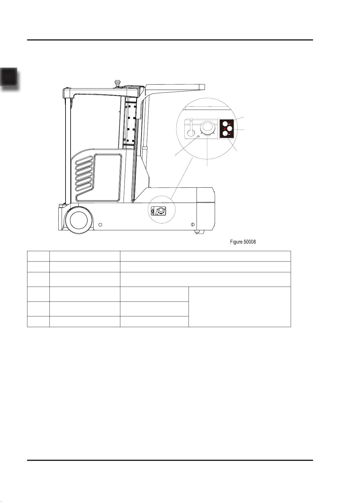
Item Control / Display Function
33 LED Lamp Display charging status
34 Emergency stop
switch
Disconnects the circuit, all electrical functions are
deactivated.
35 "Lowering" button Lower the lift
platform.
under cover,only for service
36 Low control Cooperate with the
lift and lower button
37 "Lifting" button Lift the lift platform.
33
34
35
36
37
7
REV. 07/2019
INFORMATION & SPECIFICATIONS
1
This series are electric task support vehicle. Its
important structure is as shown in Figure 50001.
-Please refer to the nameplate for rated load
capacity of the vehicle.
- The vehicle can only be used on the level gro-
und indoors, never use it on mezzanine or
balcony area.
WARNING
The truck is driven forward or backward by DC
motor. The lifting and lowering of mast can also
drive the truck, while the travel speed will be
limited.
The Electric Power Steering has greatly met the
demand for high mobility of the truck.
Truck can only be operated by single operator;
other personnel is forbidden from riding.
1.3 Common Tools
No. Name Remark
1 Hex Wrench 2#~14# One Set
2 Hex Head Socket Wrench 8#~24# One Set
3 Phillips Screwdriver 2# One Piece
4 Slotted Screwdriver 2# One Piece
5 Sockets and Knobs One Set
6 Circlip Pliers One for holes and one for shaft
7 Hammer One Piece
8 Spreader, Crane One Pair
9 Cylinder Wrenches For removal and installation of cylinders
10 Diagonal Pliers One Piece
11 Cylinder Pliers One Piece
12 Grease Gun One Piece
13 Tiger Tooth Wrench 22#/27# One of Each
WARNING
When the platform is lifted, the door will not
open. In the raised position, a pressure-
sensitive switch monitors the area between the
drive system and the operator platform. If the
area is occupied(e.g.by an object or person),
lowering is stopped. Protect operator's safety.
The truck is equipped with deadman switch,
only by pressing the switch can the truck
be operated, which has greatly reduced the
possibility of misuse by the operator.
Other manuals for LIST JX0
1
Table of contents
Other EP Equipment Truck manuals

EP Equipment
EP Equipment CQD16 User manual

EP Equipment
EP Equipment J1HD User manual

EP Equipment
EP Equipment EPT20-15ET User manual

EP Equipment
EP Equipment LIST JX0 User manual

EP Equipment
EP Equipment HPL152 User manual

EP Equipment
EP Equipment EPT16-ET User manual

EP Equipment
EP Equipment CQE12R User manual

EP Equipment
EP Equipment EPL152 User manual

EP Equipment
EP Equipment ES16-RS User manual

EP Equipment
EP Equipment CQD15S-E User manual


