Hyster C299 Operating instructions

Hyster C299 (H170FT, F175FT36, F190FT) Internal
Combustion Engine Trucks Service Repair Manual

STEERING AXLE
H6.0-7.0FT (H135-155FT) [L006];
H8.0FT, H8.0FT9, H9.0FT
(H170FT, H175FT36, H190FT) [C299]
PART NO. 4139180 1600 SRM 1952

SAFETY PRECAUTIONS
MAINTENANCE AND REPAIR
• The Service Manuals are updated on a regular basis, but may not reflect recent design changes to the
product. Updated technical service information may be available from your local authorized Hyster®
dealer. Service Manuals provide general guidelines for maintenance and service and are intended for
use by trained and experienced technicians. Failure to properly maintain equipment or to follow in-
structions contained in the Service Manual could result in damage to the products, personal injury,
property damage or death.
• When lifting parts or assemblies, make sure all slings, chains, or cables are correctly fastened, and
that the load being lifted is balanced. Make sure the crane, cables, and chains have the capacity to
support the weight of the load.
• Do not lift heavy parts by hand, use a lifting mechanism.
• Wear safety glasses.
• DISCONNECT THE BATTERY CONNECTOR before doing any maintenance or repair on electric lift
trucks. Disconnect the battery ground cable on internal combustion lift trucks.
• Always use correct blocks to prevent the unit from rolling or falling. See HOW TO PUT THE LIFT
TRUCK ON BLOCKS in the Operating Manual or the Periodic Maintenance section.
• Keep the unit clean and the working area clean and orderly.
• Use the correct tools for the job.
• Keep the tools clean and in good condition.
•Always use HYSTER APPROVED parts when making repairs. Replacement parts must meet or ex-
ceed the specifications of the original equipment manufacturer.
• Make sure all nuts, bolts, snap rings, and other fastening devices are removed before using force to
remove parts.
• Always fasten a DO NOT OPERATE tag to the controls of the unit when making repairs, or if the unit
needs repairs.
•Be sure to follow the WARNING and CAUTION notes in the instructions.
• Gasoline, Liquid Petroleum Gas (LPG), Compressed Natural Gas (CNG), and Diesel fuel are flamma-
ble. Be sure to follow the necessary safety precautions when handling these fuels and when working
on these fuel systems.
• Batteries generate flammable gas when they are being charged. Keep fire and sparks away from the
area. Make sure the area is well ventilated.
NOTE: The following symbols and words indicate safety information in this
manual:
WARNING
Indicates a hazardous situation which, if not avoided, could result in death
or serious injury.
CAUTION
Indicates a hazardous situation which, if not avoided, could result in minor
or moderate injury and property damage.
On the lift truck, the WARNING symbol and word are on orange back-
ground. The CAUTION symbol and word are on yellow background.

©2015 HYSTER COMPANY
TABLE OF CONTENTS
General .....................................................................................................................................................................1
Steering Axle Assembly Repair .............................................................................................................................. 3
Remove ................................................................................................................................................................ 3
Disassemble .........................................................................................................................................................3
Clean ....................................................................................................................................................................4
Inspect ................................................................................................................................................................. 6
Assemble ..............................................................................................................................................................6
Install ...................................................................................................................................................................6
Spindles, Bearings, and Tie Rods Repair ...............................................................................................................7
Spindles and Bearings ........................................................................................................................................ 7
Remove ............................................................................................................................................................ 7
Disassemble .................................................................................................................................................... 7
Clean ................................................................................................................................................................9
Inspect ............................................................................................................................................................. 9
Assemble ......................................................................................................................................................... 9
Install ............................................................................................................................................................ 10
Tie Rods ............................................................................................................................................................. 10
Remove .......................................................................................................................................................... 10
Install ............................................................................................................................................................ 11
Steering Cylinder Repair ...................................................................................................................................... 11
Remove and Disassemble ................................................................................................................................. 11
Clean and Inspect ............................................................................................................................................. 11
Assemble and Install ........................................................................................................................................ 12
Torque Specifications ............................................................................................................................................ 13
This section is for the following models:
H6.0-7.0FT (H135-155FT) [L006];
H8.0FT, H8.0FT9, H9.0FT (H170FT, H175FT36, H190FT) [C299]
Table of Contents
i

"THE
QUALITY
KEEPERS"
HYSTER
APPROVED
PARTS

Thanks very much for your reading,
Want to get more information,
Please click here, Then get the complete
manual
NOTE:
If there is no response to click on the link above,
please download the PDF document first, and then
click on it.
Have any questions please write to me:
admin@servicemanualperfect.com

General
This section has the description and repair
procedures for the steering axle.
The steering axle assembly includes an axle frame,
steering cylinder, and two spindle and hub
assemblies. See Figure 1. The steering axle is
articulated and is connected to the frame with two
mounting plates and four capscrews and washers.
See Figure 2.
The end caps of the steering cylinder are also the
mounts for the cylinder and are held to the shell by
the mount capscrews. There are O-rings, seals, and
wipers in the end caps to seal the caps to the shell
and rod. The ends of the piston rod extend from
both ends of the cylinder. A single piston and the
seal are at the center of the rod. Oil pressure on one
side of the piston moves the piston in the bore. The
piston pushes an equal amount of oil from the
opposite side of the cylinder.
When the piston reaches the end of the stroke, a
relief valve in the steering circuit controls the oil
pressure. The tie rods that connect the spindle
arms to the cylinder are not adjustable. See
Figure 1.
Each spindle turns on two tapered roller bearings
in mounts in the axle frame. The preload on the
bearings is controlled by shims at the lower bearing
cap.
1. HUB ASSEMBLY
2. AXLE FRAME
3. BUSHING
4. STUB SHAFT
5. STEERING CYLINDER
6. TIE ROD
7. LUBE FITTING
8. SPINDLE
Figure 1. Steering Axle Arrangement
1600 SRM 1952 General
1

The wheels rotate on two tapered roller bearings
and are held on the spindles by a castle nut. The
bearing preload of the wheels is adjusted by the
castle nut. The grease seals protect the bearings
from dirt and water. Wear sleeves protect the hub
from wear by the seals.
For information on performing regular
maintenance and service on the steering axle, see
service manual
Periodic Maintenance 8000SRM1957 for lift
truck models
• H6.0-7.0FT (H135-155FT) (L006)
Periodic Maintenance 8000SRM1959 for lift
truck models
• H8.0FT, H8.0FT9, H9.0FT (H170FT,
H175FT36, H190FT) (C299)
For information related to lift truck capacities and
specifications, see service manual
Capacities and Specifications 8000SRM1958 for
lift truck models
• H6.0-7.0FT (H135-155FT) (L006)
Capacities and Specifications 8000SRM1960 for
lift truck models
• H8.0FT, H8.0FT9, H9.0FT (H170FT,
H175FT36, H190FT) (C299)
1. CAPSCREW AND WASHER
2. MOUNTING PLATE
3. FRAME
4. STEERING AXLE
5. STUB SHAFT AND BUSHING
Figure 2. Steering Axle Mounting Arrangement
General 1600 SRM 1952
2

Steering Axle Assembly Repair
REMOVE
WARNING
PUTTING THE LIFT TRUCK ON BLOCKS
The lift truck must be put on blocks for some
types of maintenance and repair. The removal of
the mast, drive axle, battery, or counterweight as-
semblies will cause large changes in the center of
gravity. When the lift truck is put on blocks, put
additional blocks in the following positions:
• If the mast and drive axle are removed, put
blocks under the counterweight so the lift
truck cannot fall backward.
• If the counterweight is removed, put blocks
under the mast so that the lift truck cannot
fall forward.
Put the lift truck on blocks on a solid, even, and
level surface. Verify the blocks or stands have
enough capacity to hold the lift truck. Use addi-
tional blocks next to the tires as necessary to pre-
vent movement of the lift truck. Verify the lifting
devices used during repairs can lift the weight of
the parts and assemblies.
See the Operating Manual or Periodic Mainte-
nance manual listed in the General section of this
manual for the procedures to put the lift truck on
blocks.
NOTE: The steering axle can be removed without
removing the counterweight.
1. Verify wheels are set for straight travel. Put lift
truck on blocks so the steering axle will have
enough clearance to be removed. The top of the
axle frame must have clearance under the bot-
tom of the frame at the rear of the lift truck.
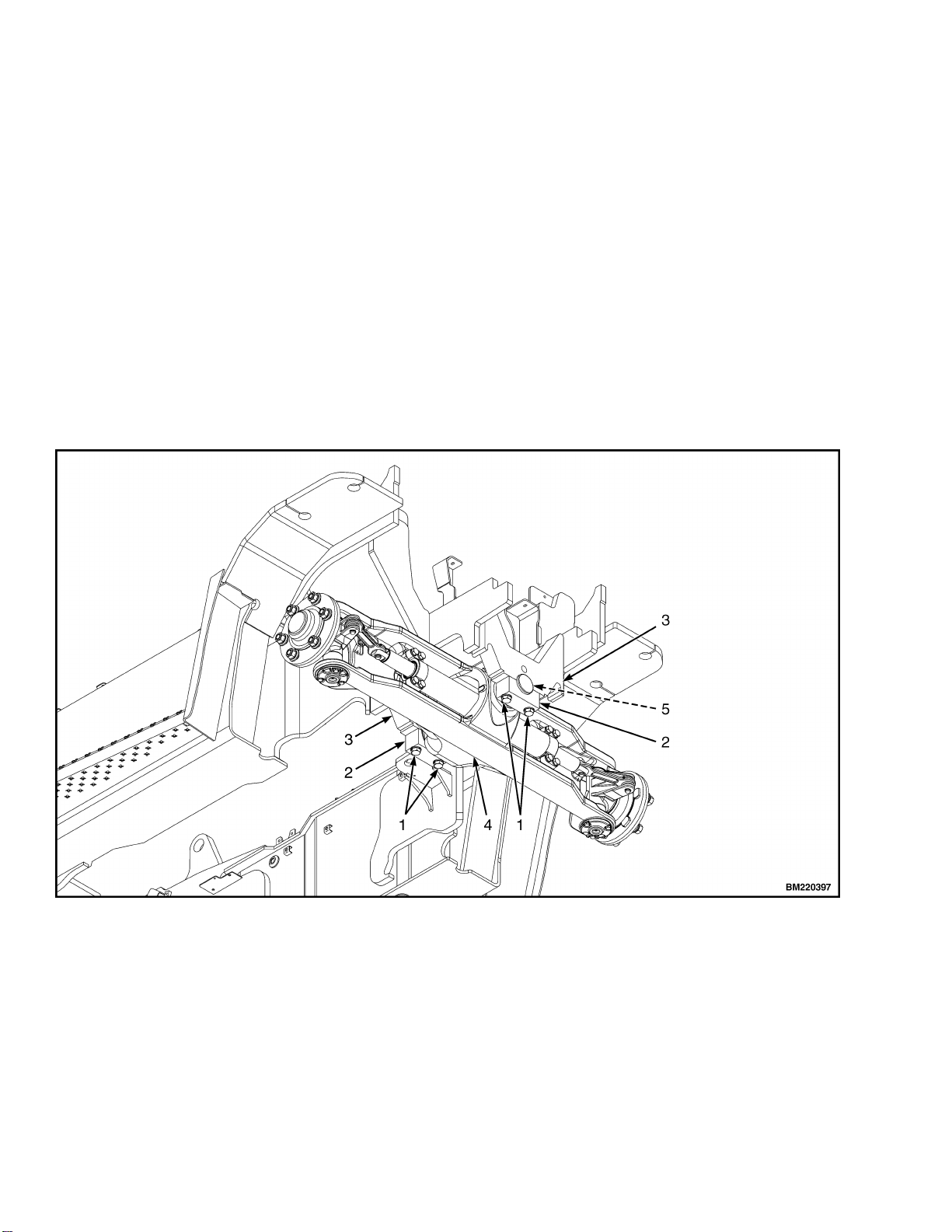
2. Disconnect hydraulic lines at steering cylinder.
Install plug fittings in cylinder and put caps on
hydraulic lines. Plug fittings will prevent spin-
dles from turning as axle is removed from un-
der the lift truck. See Figure 3.
3. Slide floor jack or forks of another lift truck un-
der steering axle. Raise lifting device until it
holds the weight of the axle assembly.
4. Remove four capscrews and washers from two
mounting plates on bottom of steering axle and
lift truck frame. See Figure 3.
5. Remove mounting plates and slowly lower
steering axle assembly onto wheels. Carefully
roll steering axle assembly away from lift truck.
DISASSEMBLE
NOTE: If the spindle, bearings or tie rods need to
be repaired, go to Spindles, Bearings, and Tie Rods
Repair section for repair procedures.
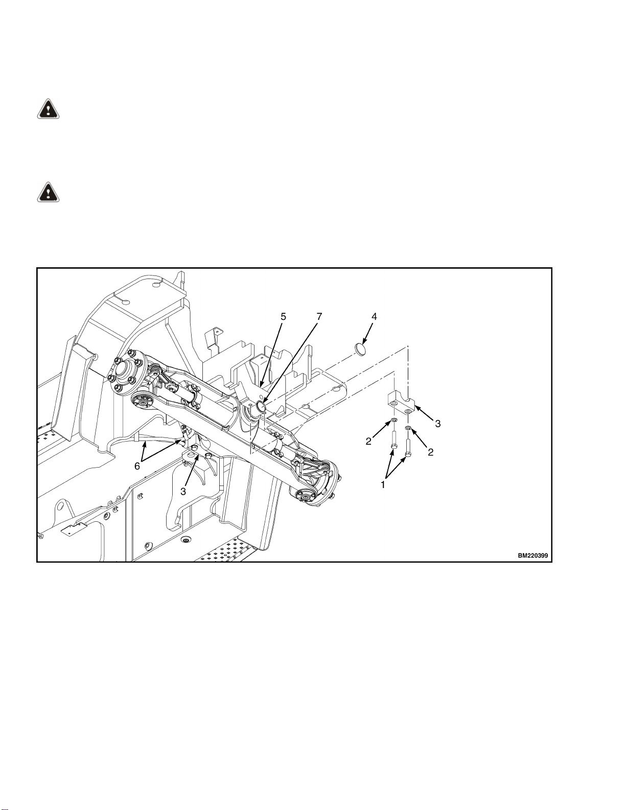
1. Remove ring seal, shims, flange, stub shaft and
bushing from steering axle assembly. See Fig-
ure 4.
2. Put axle on blocks so the wheels just touch the
floor. Remove hub cap. Remove cotter pin,
washer, and castle nut. Remove bearing cone
and discard cotter pin.
NOTE: Identify and tag the outer and inner bear-
ing cones so they can be reassembled in their origi-
nal locations.
3. Slide wheel from spindle. Remove inner bearing
cone, wear ring, and oil seal from spindle. See
Figure 3.
NOTE: If the bearing is replaced, then the associ-
ated bearing cup must be replaced also.
4. If the bearings must be replaced, use a brass
drift pin to remove the bearing cups and wear
ring.
5. Repeat Step 1 through Step 4 for other wheel.
1600 SRM 1952 Steering Axle Assembly Repair
3

CLEAN
WARNING
Cleaning solvents can be flammable and toxic and
can cause skin irritation. When using cleaning
solvents, always follow the solvent manufac-
turer’s recommended safety procedures.
WARNING
Compressed air is used for cleaning or drying
purposes, or for clearing restrictions. Wear pro-
tective clothing (goggles/shield, gloves, etc.) to
avoid injury to personnel.
1. Clean bearings by placing them in a wire bas-
ket and immersing in a container of fresh sol-
vent. Agitate the bearings in the solvent to re-
move all traces of old lubricant.
2. After cleaning the bearings, dry them with
clean compressed air. Take care to prevent
spinning the bearings when using a compressed
air jet.
3. Immediately wrap bearings in a lint-free cloth
to protect them from dust and other foreign
matter.
1. CAPSCREW
2. WASHER
3. MOUNTING PLATE
4. PLUG
5. FRAME MOUNT
6. STEERING AXLE HYDRAULIC LINES
7. STUB SHAFT
Figure 3. Steering Axle, Remove
Steering Axle Assembly Repair 1600 SRM 1952
4

1. STEER AXLE ASSEMBLY
2. TIE ROD
3. RING SEAL
4. SHIM
5. FLANGE
6. SHIM
7. BUSHING
8. STUB SHAFT
9. STEERING CYLINDER
10. STEERING CYLINDER ROD
11. GREASE FITTING
12. COTTER PIN
13. HUB CAP
14. CASTLE NUT
15. WASHER
16. WHEEL HUB
17. BEARING CUP (OUTER)
18. BEARING CONE (OUTER)
19. BEARING CUP (INNER)
20. BEARING CONE (INNER)
21. WEAR RING
22. OIL SEAL
23. SPINDLE
24. LUBE FITTING
Figure 4. Steering Axle, Disassemble
1600 SRM 1952 Steering Axle Assembly Repair
5

INSPECT
1. Inspect for loose, burned, missing, cracked or
damaged hardware.
2. Inspect all parts for dents, holes, bends, burrs,
rust, corrosion or marred finish.
ASSEMBLE
NOTE: For specified lubricant to use, see the Peri-
odic Maintenance manual listed in the General
section of this manual.
1. If necessary, use a press to install new bearing
cups in wheel or hub. See Figure 5.
2. Lubricate bearing cones with multipurpose
grease. Verify bearings are filled with grease.
Install oil seal, wear ring (if removed) and inner
bearing cone on spindle.
CAUTION
DO NOT damage the seals during installation.
3. Carefully slide wheel onto spindle. Install outer
bearing cone and install washer. See Figure 5.
NOTE: Ensure that the washer is seated properly
against the bearing cone and not against the shaft
shoulder before tightening the castle nut.
4. Install the castle nut and tighten castle nut as
described below:
• Tighten castle nut to
203 N•m (150 lbf ft) while rotating the
wheel in both directions to properly seat
the bearings. Loosen the castle nut until
wheel turns freely with no end play.
Tighten castle nut to 34 N•m (25 lbf ft).
5. Install new cotter pin in castle nut. If cotter pin
cannot be installed, tighten castle nut to the
first alignment position where the cotter pin
can be installed.
6. Install hub cap. See Figure 5.
7. Repeat Step 1 through Step 6 for other wheel.
NOTE: Apply multipurpose grease to stub shaft
prior to installing. See the Periodic Maintenance
manual listed in the General section of this manual
for grease specifications.
8. Install stub shaft, bushing, shims, flange, and
rig seal to steering axle assembly. See Figure 4.
INSTALL
1. Use floor jack or another lift truck to put steer-
ing axle into position in frame.
2. Attach steering axle to lift truck frame with
two mounting plates, four washers, and four
capscrews. Tighten capscrews to
270 N•m (199 lbf ft). See Figure 3.
3. Remove plugs and caps and connect hydraulic
lines to steering cylinder. See Figure 3.
4. Operate steering system to remove air from
system. Turn steering wheel several times from
one stop to the other. Check for hydraulic leaks.
NOTE: RIGHT SIDE SHOWN.
1. HUB ASSEMBLY
2. HUB CAP
3. COTTER PIN
4. CASTLE NUT
5. WASHER
6. OUTER BEARING CUP AND CONE
7. INNER BEARING CUP AND CONE
8. SEAL
Figure 5. Bearing Arrangement
Steering Axle Assembly Repair 1600 SRM 1952
6

Spindles, Bearings, and Tie Rods Repair
SPINDLES AND BEARINGS
Remove
WARNING
PUTTING THE LIFT TRUCK ON BLOCKS
The lift truck must be put on blocks for some
types of maintenance and repair. The removal of
the mast, drive axle, battery, or counterweight as-
semblies will cause large changes in the center of
gravity. When the lift truck is put on blocks, put
additional blocks in the following positions:
• If the mast and drive axle are removed, put
blocks under the counterweight so the lift
truck cannot fall backward.
• If the counterweight is removed, put blocks
under the mast so that the lift truck cannot
fall forward.
Put the lift truck on blocks on a solid, even, and
level surface. Verify the blocks or stands have
enough capacity to hold the lift truck. Use addi-
tional blocks next to the tires as necessary to pre-
vent movement of the lift truck. Verify the lifting
devices used during repairs can lift the weight of
the parts and assemblies.
See the Operating Manual or Periodic Mainte-
nance manual listed in the General of this manual,
for the procedures to put the lift truck on blocks.
1. Put the lift truck on blocks.
2. Remove the wheel and bearings. See Steering
Axle Assembly Repair for procedures.
3. Remove two snap rings and washers from the
pin holding the tie rod to steering cylinder rod
and remove pin. See Figure 6.
CAUTION
DO NOT hit the threads of the tie rod.
4. Remove snap rings, washers and pin. Remove
tie rod end from spindle arm. See Figure 6.
5. If necessary, repeat above steps for other spin-
dle and tie rod.
Disassemble
1. Remove plug from the top of spindle. Remove
the capscrews from the bearing cap. Remove
the bearing cap and shims. If necessary, re-
move the bearing cup from the bearing cap. See
Figure 7.
2. Tilt the spindle and lift the spindle from the
axle. If necessary, remove the bearing and seals
from the spindle. If necessary, remove the wear
sleeve and bearing cup from the axle frame.
3. If necessary, repeat above steps for other spin-
dle and tie rod.
1600 SRM 1952 Spindles, Bearings, and Tie Rods Repair
7

1. SNAP RING
2. PIN
3. STEERING CYLINDER
4. SEAL
5. TIE ROD ASSEMBLY
6. SPINDLE (LEFT SIDE SHOWN)
Figure 6. Tie Rod Assembly
Spindles, Bearings, and Tie Rods Repair 1600 SRM 1952
8

1. PRY BAR
2. BEARING CUP
3. BEARING CAP
4. O-RING
Figure 7. Bearing Cup Removal
Clean
WARNING
Cleaning solvents can be flammable and toxic and
can cause skin irritation. When using cleaning
solvents, always follow the solvent manufac-
turer’s recommended safety procedures.
WARNING
Compressed air is used for cleaning or drying
purposes, or for clearing restrictions. Wear pro-
tective clothing (goggles/shield, gloves, etc.) to
avoid injury to personnel.
1. Clean bearings by placing them in a wire bas-
ket and immersing in a container of fresh sol-
vent. Agitate the bearings in the solvent to re-
move all traces of old lubricant.
2. After cleaning the bearings, dry them with
clean compressed air. Take care to prevent
spinning the bearings when using a compressed
air jet.
3. Immediately wrap bearings in a lint-free cloth
to protect them from dust and other foreign
matter.
Inspect
1. Inspect for loose, missing, cracked, burned or
damaged hardware.
2. Inspect all parts for dents, holes, bends, burrs,
rust, corrosion, or marred finish.
Assemble
1. Install new seals on the spindle. Lubricate the
seals with grease. If necessary, press new bear-
ing cones on the spindle.
2. Lubricate the bearings with wheel bearing
grease. Verify the bearings are filled with
grease. If necessary, press the new bearing
cups into the steering axle frame and bearing
cap. Install the wear sleeve in the steering axle
frame.
3. Install the spindle in the steering axle. Install
the bearing cap without the O-rings. See Fig-
ure 8.
Measure the clearance between the bearing cap
and the axle. Remove the bearing cap and install
enough shims to provide a preload of 0.00 to
0.13 mm (0.000 to 0.005 in.).
NOTE: The spindle bearings must have no clear-
ance. Install shims 0.00 to 0.13 mm (0.000 to
0.005 in.) less than the measured gap.
4. Install the O-ring on the bearing cap. Apply
Loctite ® 242 to threads of capscrews. Install
the bearing cap and capscrews. Tighten cap-
screws to 47 N•m (35 lbf ft).
5. If necessary, repeat the steps above for the
other spindle and tie rod.
1600 SRM 1952 Spindles, Bearings, and Tie Rods Repair
9

NOTE: THE LUBRICATION FITTING NEEDS TO BE
ORIENTED 45° TO CENTERLINE AND REAR OF
LIFT TRUCK.
1. SNAP RING
2. PIN
3. SEAL
4. TIE ROD
5. SEAL
6. BEARING CONE (LOWER)
7. O-RING
8. BEARING CUP (LOWER)
9. SEAL
10. SHIM
11. BEARING CAP
12. CAPSCREW
13. LUBE FITTING
14. OIL SEAL
15. WEAR SLEEVE
16. BEARING CONE (INNER)
17. BEARING CUP (INNER)
18. BEARING CONE (OUTER)
19. BEARING CUP (OUTER)
20. HUB
21. COTTER PIN
22. WASHER
23. CASTLE NUT
24. HUB CAP
25. SEAL
26. WEAR SLEEVE
27. BEARING CUP (UPPER)
28. BEARING CONE (UPPER)
29. PLUG
Figure 8. Spindle Assembly
Install
1. Install tie rod end to spindle arm and steering
cylinder with pins, seals and snap rings. See
Figure 6.
2. Install plug on the top of the spindle.
3. Install the bearings and wheel. See Steering
Axle Assembly Repair for procedures.
4. If necessary, repeat the procedure for the other
spindle and tie rod.
5. Remove lift truck from blocks.
TIE RODS
Remove
WARNING
PUTTING THE LIFT TRUCK ON BLOCKS
The lift truck must be put on blocks for some
types of maintenance and repair. The removal of
the mast, drive axle, battery, or counterweight as-
semblies will cause large changes in the center of
gravity. When the lift truck is put on blocks, put
additional blocks in the following positions:
• If the mast and drive axle are removed, put
blocks under the counterweight so the lift
truck cannot fall backward.
• If the counterweight is removed, put blocks
under the mast so that the lift truck cannot
fall forward.
Put the lift truck on blocks on a solid, even, and
level surface. Verify the blocks or stands have
enough capacity to hold the lift truck. Use addi-
tional blocks next to the tires as necessary to pre-
vent movement of the lift truck. Verify the lifting
devices used during repairs can lift the weight of
the parts and assemblies.
See the Operating Manual or Periodic Mainte-
nance manual listed in the General of this manual,
for the procedures to put the lift truck on blocks.
1. Put the lift truck on blocks.
Spindles, Bearings, and Tie Rods Repair 1600 SRM 1952
10

2. Remove the wheel and if necessary, the bear-
ings. See Steering Axle Assembly Repair sec-
tion for procedures.
3. Remove the snap rings from the pin retaining
the tie rod to the spindle. Remove the pin. To
loosen and remove the pin, use a brass punch
and hammer. See Figure 6.
4. Remove the snap rings from the pin retaining
the tie rod to the steering cylinder rod. Remove
the pin.
5. Slide the tie rod and washers from the spindle
housing and steering cylinder rod. See Figure 6.
Install
1. Place the tie rod and washers in position in the
spindle and steering cylinder rod. See Figure 6.
2. Align holes and place lubricated pin into the
spindle and tie rod. Install the two snap rings
on top and bottom of pin.
3. Align holes and place lubricated pin into the
steering cylinder rod and tie rod. Install the
two snap rings on top and bottom of pin. See
Figure 6.
4. If removed, install the bearings and install the
wheel. See Steering Axle Assembly Repair for
procedures.
5. Repeat the procedure for the other tie rod.
6. Remove the lift truck from blocks.
Steering Cylinder Repair
REMOVE AND DISASSEMBLE
CAUTION
Disposal of lubricants and fluids must meet local
environmental regulations.
NOTE: The end caps of the steering cylinder are
held in the shell by the installation of cylinder
mount capscrews into the axle frame. To prevent oil
leaks at the caps, hold the caps on the cylinder
shell during removal.
1. Disconnect and tag hydraulic lines at steering
cylinder. See Figure 9. Install caps in fittings
on cylinder and put fittings on hydraulic lines.
2. Remove the tie rods. See Spindles, Bearings,
and Tie Rods Repair section for procedures.
3. Remove capscrews that fasten cylinder to axle
frame. Hold end caps on cylinder shell and re-
move steering cylinder.
4. Hold end of steering cylinder over a container.
Remove plug for hydraulic fitting from each end
cap. Push rod toward end of shell that is over
container. Oil will drain from cylinder. Repeat
procedure for other end.
5. Carefully remove one end cap from shell and
slide off of rod. Carefully pull rod out of shell,
keeping rod centered in shell during removal.
Remove other end cap from shell. Remove all
seals, wipers, and O-rings. See Figure 9.
6. Remove piston seal and two guide rings.
CLEAN AND INSPECT
WARNING
Cleaning solvents can be flammable and toxic and
can cause skin irritation. When using cleaning
solvents, always follow the solvent manufactur-
er's recommended safety procedures.
1. Clean all metal parts in solvent.
2. Inspect piston rod for grooves or damage. Re-
move small scratches with fine emery cloth.
3. Inspect cylinder bore for damage
4. Inspect mounts for cracks.
1600 SRM 1952 Spindles, Bearings, and Tie Rods Repair
11

ASSEMBLE AND INSTALL
CAUTION
Do not damage the O-rings, seals, or wipers dur-
ing installation.
1. Put O-rings, seals, guide rings, and wipers in
warm hydraulic oil.
2. Install O-rings, seals, guide rings, and wipers
as shown in Figure 9.
3. Lubricate O-rings, seals, and wipers with O-
ring lubricant and carefully install one end cap
on cylinder rod.
4. Carefully slide cylinder rod into cylinder shell
and end onto shell. Keep cylinder rod aligned in
center of cylinder shell during installation so
the parts are not damaged. Install other end
cap into shell. Put caps on hydraulic fittings of
end caps.
5. Hold end caps and install cylinder on axle
frame using capscrews. Tighten capscrews to
225 N•m (166 lbf ft).
6. Install tie rods. See Spindles, Bearings, and Tie
Rods Repair for procedures.
7. Remove plugs and caps and connect hydraulic
lines as tagged during removal, to steering cyl-
inder. Operate steering system to remove air
from cylinders and system. Turn steering wheel
several times from one stop to the other. Check
that the steer cylinder operates lock to lock.
Figure 9. Steering Cylinder
Steering Cylinder Repair 1600 SRM 1952
12

Legend for Figure 9
1. CYLINDER SHELL
2. BACKUP RING
3. O-RING
4. ROD SEAL
5. END CAP
6. ROD WIPER
7. GUIDE RING
8. PISTON SEAL
9. CYLINDER ROD
10. HYDRAULIC LINE PORT
Torque Specifications
Axle Mounting Bolts and Nuts
270 N•m (199 lbf ft)
Hub Nut (Initial)
203 N•m (150 lbf ft)
Hub Nut (Final)
34 N•m (25 lbf ft)
Spindle Bearing Cap Capscrews
47 N•m (35 lbf ft)
Steer Cylinder Mounting Bolts
225 N•m (166 lbf ft)
1600 SRM 1952 Steering Cylinder Repair
13

NOTES
14
This manual suits for next models
3
Table of contents
Other Hyster Truck manuals
Popular Truck manuals by other brands

Wollard Airport Equipment
Wollard Airport Equipment TC-888 Operator

EP Equipment
EP Equipment LIST JX0 Operation manual

SAC
SAC TURBO-MAX 6046 Operator's manual

Daewoo
Daewoo Novus M2SEF manual

Super Products
Super Products Camel 1200 (Ejector Unloading) Operator's manual

Versalift
Versalift TEL-29-N Operator's manual