Epever MT11 User manual

Remote Meter
User Manual
MT11


Contents
1. Important Safety Instructions ...................................................................1
2. Overview.................................................................................................2
3. Product Classification..............................................................................3
4. Installation...............................................................................................4
4.1 Base of MT11 (Optional accessory)...................................................4
4.2 Wall Installation .................................................................................5
4.3 Surface Installation............................................................................6
5. Product Features.....................................................................................8
5.1 Front View.........................................................................................8
5.2 Rear View........................................................................................10
6. Display and operation............................................................................12
6.1 LCD.................................................................................................12
6.2 Auto Global-View Mode...................................................................14
6.3 Temperature Units...........................................................................15
6.4 Clear the Generated Energy............................................................16
6.5 Battery Type....................................................................................16
6.6 Fault Indication................................................................................21
7. Specifications........................................................................................22
8. Warranty ...............................................................................................23

1
1. Important Safety Instructions
Thank you for selecting the remote meter.
General safety information
Please contact our company or transportation if the product has been
damaged.
Please read this manual carefully before using the product and pay
attention to the safety information.
Keep the product away from rain, exposure, severe dust, vibrations,
corrosive gas, and intense electromagnetic interference.
Do not allow water to enter the product.
There are no serviceable parts inside the product. Do not disassemble
or attempt to repair it.
Recommendations
The MT11 is only allowed to connect with the DR-N series charge
controller. Please confirm before purchase and installation.
Please do not install MT11 in a situation with strong electromagnetic
interference.

2
2. Overview
The MT11 remote meter, matching with the DuoRacer series controllers, can
monitor the controller's running data and working status.
Features:
Easy to install and operate
Real-time display of fault alarms
Locally readable of real-time parameters
Powered by the controller directly

3
3. Product Classification
1) MT11(include the 1.5m communication cable)
Remote meter MT11
1.5m communication cable (Model: CC-RS485-RS485-3.81-4P-150)
Base of MT11
2) MT11 (include the 5m communication cable)
Remote meter MT11
5m communication cable (Model: CC-RS485-RS485-3.81-4P-500)
Base of MT11
3) MT11 (include the 10m communication cable)
Remote meter MT11
10m communication cable (Model: CC-RS485-RS485-3.81-4P-1000)
Base of MT11
4) MT11(Do not include the communication cable)
Remote meter MT11
1.5m communication cable (Model: CC-RS485-RS485-3.81-4P-150)
Do not include Base of MT11
NOTE: The customers can purchase the product according to the
requirement.
4
4. Installation
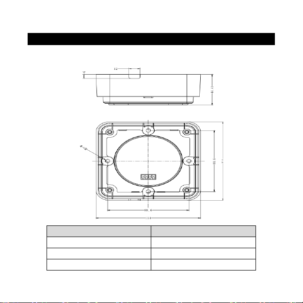
4.1 Base of MT11 (Optional accessory)
Mechanical parameter
Parameter
Dimension
114mm x 114mm x 44.41mm
Mounting size
88.6mm x 88.6mm
Mounting hole size
Φ5mm
5
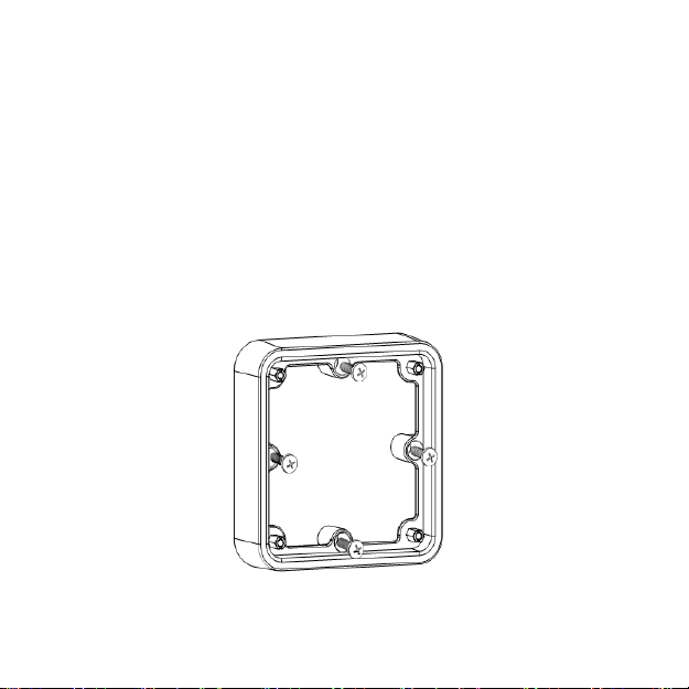
4.2 Wall Installation
Step1: Locate and drill screw holes based on the Frame Mounting
dimension of the base, and erect the plastic expansion bolts.
Step2: Use four PA4.2×32 self-tapping screws to fix the Frame.
Step3: Remove the decorative shell.
Step4: Use four M4×8 pan head screws to mount the MT11 surface on the
Frame.
Step5: Install the decorative shell.

6
4.3 Surface Installation

7
Step1: Locate and drill screw holes based on the installation size of the
surface.
Step2: Remove the decorative shell.
Step3: Use four M4×8 cross recessed pan head screws with M4 nuts to
mount the MT11 surface onto the panel.
Step4: Install the decorative shell.
NOTE: Take full consideration of the plugging/unplugging space of the
communication cable and the cable length during installation.

8
5. Product Features
5.1 Front View
LCD screen
Man-machine interaction operation interface. Refer to chapter 6, Display
and operation.
Buttons
The meter buttons include two function buttons and one switch button.

9
Press the button
1. PV array parameters
2. Storage battery parameters
3. Browse the start battery
parameters automatically ( )
Press the button
Browse the PV array parameters
Browse the Storage battery
parameters
Browse the start battery parameters
Press the button and hold on 5s
Temperature unitsBattery type
Press the button
The meter is powered ON
Press the button and hold on 5s
The meter is powered OFF
10
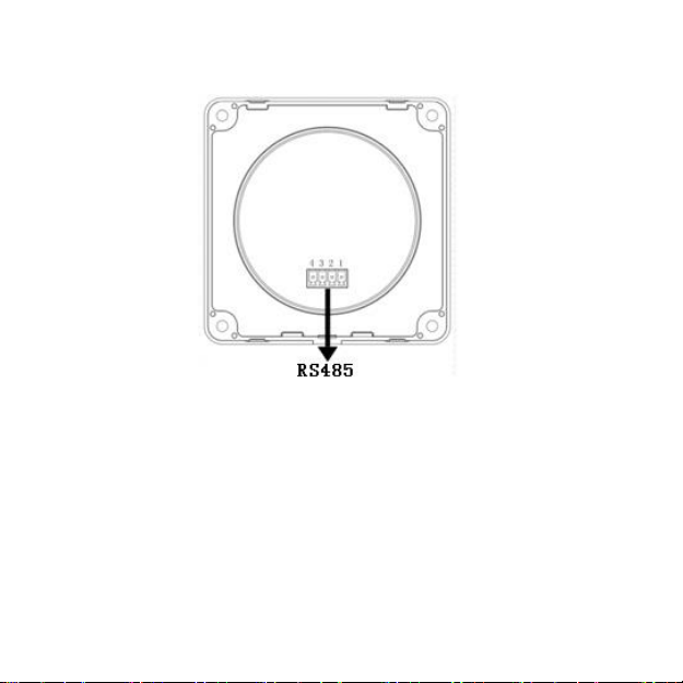
5.2 Rear View
RS485communicationport
It is used to connect the controller to supply power to the MT11.
Communicationcable’s models
CC-RS485-RS485-3.81-4P-150(Included)
CC-RS485-RS485-3.81-4P-1000(Optional)
CC-RS485-RS485-3.81-4P-2000(Optional)
11
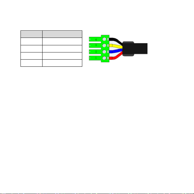
Pins definition
PIN
Definition
1
DC5V
2
RS-485-B
3
RS-485-A
4
GND
12
6. Display and operation
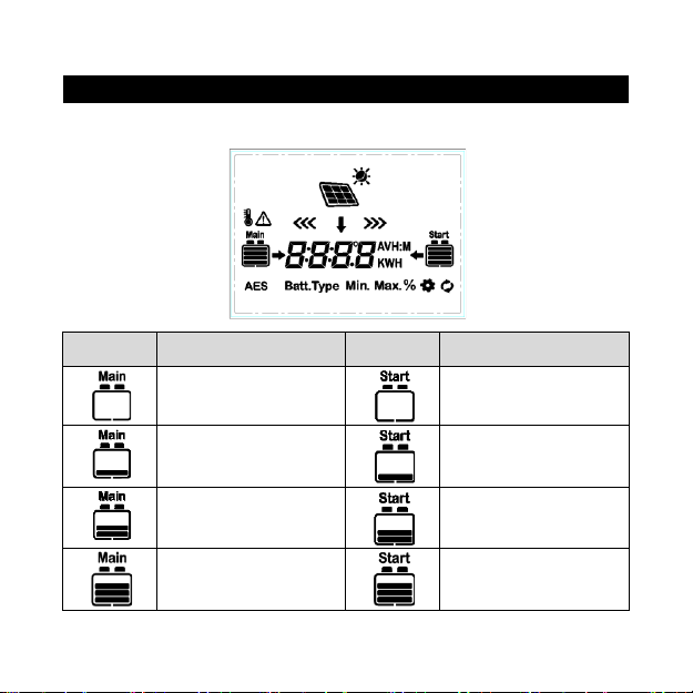
6.1 LCD
Icon
Instruction
Icon
Instruction
BATT1 battery capacity
level①0~12%
BATT2battery capacity
level①0~12%
BATT1battery capacity
level①13%~35%
BATT2battery capacity
level①13%~35%
BATT1battery capacity
level①36%~61%
BATT2battery capacity
level①36%~61%
BATT1battery capacity
level①62%~86%
BATT2battery capacity
level①62%~86%

13
BATT1battery capacity
level①
87%~100%
BATT2battery capacity
level①
87%~100%
Day
PV array
Night
BATT1 charging icon
Display the parameters of
PV
BATT2charging icon
Display the parameters of
BATT1
BATT1temperature
parameters
Display the parameters
of BATT2
AES signal icon
Setting icon
Battery type icon
Auto global view sign
Minimum voltage icon
Fault Icon
Maximum voltage icon
①Battery power capacity is calculated by the linear relationship between the
disconnect voltage of low voltage and float charging voltage.

14
6.2 Auto Global-View Mode
Operation:
Step1: Press the button, is appear.
Step2: Press the button and select the .
15
Echo Loop: PV voltage ——PV current ——PV power——Battery power—
—BATT1 voltage——BATT1 current——Max. BATT1 voltage——
Min.BATT1 voltage——BATT1 temperature——BATT1 battery type——
BATT2 voltage——BATT2 current——Max. BATT1 voltage——Min.BATT2
voltage——PV voltage
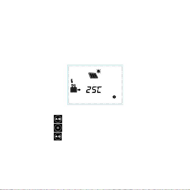
6.3 Temperature Units
Operation:
Step1: Press the button under the battery temperature interface.
Step2: Press the button to select the temperature unit.
Step3: Press the button to set successfully.

16
6.4 Clear the Generated Energy
Press the and button and hold on 5s to clear the generated energy.
6.5 Battery Type
1) Operation:
Step1: Press the button and hold 5s under the battery type interface.
Step2: Press the button when the battery type interface is flashing.
Step3: Press the button to confirm the battery type.

17
2) Battery type
BATT112V Sealed
BATT124V Sealed
BATT112V Gel
BATT124V Gel
BATT112V Flooded
BATT124V Flooded
LiFePO4(4S)
LiFePO4(8S)
Li-NiCoMn (3S)
Li-NiCoMn (6S)
User
CAUTION: The battery voltage is set as default and not
changeable when selecting the default battery type. Please change
to "User" battery type before adjusting the battery voltage.
CAUTION: Set the voltage of the "User" battery type via PC software
only.
3) Lead-acid Battery Control Voltage Parameters
The parameters are in the 12V system at 25 ºC. Please double the values in
the 24V system.
Battery type
Voltage parameter
Sealed
Gel
Flooded
User
Over Voltage Disconnect Voltage
16.0V
16.0V
16.0V
9~17V
Charging Limit Voltage
15.0V
15.0V
15.0V
9~17V
This manual suits for next models
1
Table of contents
Other Epever Measuring Instrument manuals


Popular Measuring Instrument manuals by other brands

CommScope
CommScope OneCell Hardware installation guide

Fast
Fast Lokal 400 operating manual

METROTEC
METROTEC VNA-70A instruction manual

BRANNSTROM
BRANNSTROM CleanTrack 1000 B Operation and technical manual

Kobold
Kobold Heinrichs BGN Series Installation and operating instructions

Stanley
Stanley FatMax TruLaser TLM 300 user manual


