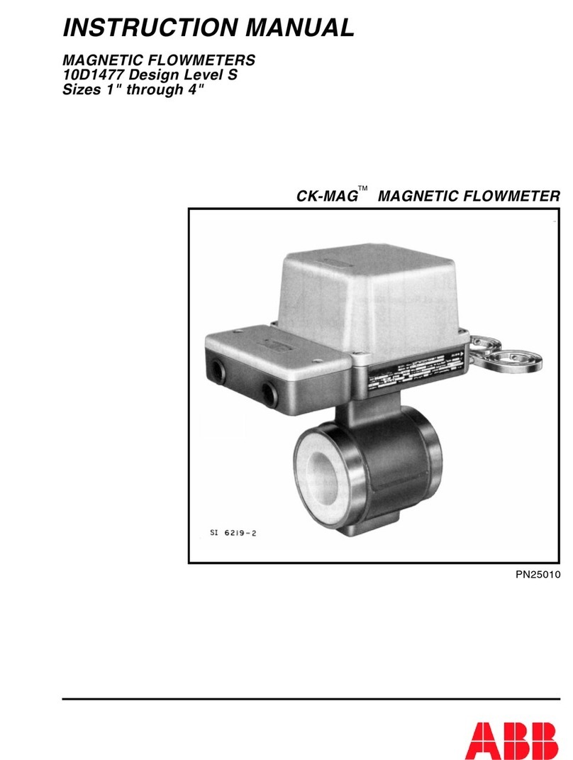
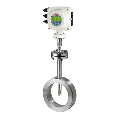
ABB MAG-X 3000 Series User manual

INSTRUCTION MANUAL
MAGNETIC FLOWMETERS
10DX3111 Design Levels A & G
Sizes 14 through 24 Inches
MAG-X
SERIES 3000 MAGNETIC FLOWMETER
PN24989

The following are trademarks of ABB Automation:
COPA-XM
MAG-X®
The following is a registered trademark of E. I. du Pont de Nemours and Company:
TEFLON®
The following is a trademark of Haynes International Incorporated:
HASTELLOY
The following is a trademark of International Nickel Company, Incorporated:
MONEL
WARNING notices as used in this manual apply to hazards or unsafe practices which could result in personal
injury or death.
CAUTION notices apply to hazards or unsafe practices which could result in property damage.
NOTES highlight procedures and contain information which assist the operator in understanding the information
contained in this manual.
All software, including design, appearance, algorithms and source codes, is owned and copyrighted by ABB
Automation and is owned and copyrighted by ABB Automation or its suppliers.
WARNING
POSSIBLE PROCESS UPSETS
Maintenance must be performed only by qualified personnel and only after securing equipment controlled
by this product. Adjusting or removing this product while it is in the system may upset the process being
controlled. Some process upsets may cause injury or damage.
NOTICE
The information contained in this document is subject to change without notice.
ABB Automation, its affiliates, employees, and agents, and the authors of and contributors to this
publication specifically disclaim all liabilities and warranties, express and implied (including warranties of
merchantability and fitness for a particular purpose), for the accuracy, currency, completeness, and/or
reliability of the information contained herein and/or for the fitness for any particular use and/or for the
performance of any material and/or equipment selected in whole or part with the user of/or in reliance upon
information contained herein. Selection of materials and/or equipment is at the sole risk of the user of this
publication.
This document contains proprietary information of ABB Automation, and is issued in strict confidence. Its
use, or reproduction for use, for the reverse engineering, development or manufacture of hardware or
software described herein is prohibited. No part of this document may be photocopied or reproduced
without the prior written consent of ABB Automation.
Copyright 2001 ABB Automation [March 2001]

Table of Contents
SAFETY SUMMARY . . . . . . . . . . . . . . . . . . . . . . . . . . . . . . . . . . . . . . . . . . . . . . . . . . . . . I
READ FIRST . . . . . . . . . . . . . . . . . . . . . . . . . . . . . . . . . . . . . . . . . . . . . . . . . . . . . . . . . . III
1.0 INTRODUCTION . . . . . . . . . . . . . . . . . . . . . . . . . . . . . . . . . . . . . . . . . . . . . . . . . . 1-1
1.1 General. . . . . . . . . . . . . . . . . . . . . . . . . . . . . . . . . . . . . . . . . . . . . . . . . . . . . . . . . . . . . . . . . . . . 1-1
1.1.1 Description . . . . . . . . . . . . . . . . . . . . . . . . . . . . . . . . . . . . . . . . . . . . . . . . . . . . . . . . . . . . 1-1
1.1.2 Construction . . . . . . . . . . . . . . . . . . . . . . . . . . . . . . . . . . . . . . . . . . . . . . . . . . . . . . . . . . . 1-2
1.2 Model Number Breakdown. . . . . . . . . . . . . . . . . . . . . . . . . . . . . . . . . . . . . . . . . . . . . . . . . . . . . 1-3
1.2.1 Model 10DX3111A/G . . . . . . . . . . . . . . . . . . . . . . . . . . . . . . . . . . . . . . . . . . . . . . . . . . . . 1-4
1.3 Specifications . . . . . . . . . . . . . . . . . . . . . . . . . . . . . . . . . . . . . . . . . . . . . . . . . . . . . . . . . . . . . . . 1-6
2.0 INSTALLATION. . . . . . . . . . . . . . . . . . . . . . . . . . . . . . . . . . . . . . . . . . . . . . . . . . . 2-1
2.1 Inspection . . . . . . . . . . . . . . . . . . . . . . . . . . . . . . . . . . . . . . . . . . . . . . . . . . . . . . . . . . . . . . . . . . 2-1
2.2 Meter Handling . . . . . . . . . . . . . . . . . . . . . . . . . . . . . . . . . . . . . . . . . . . . . . . . . . . . . . . . . . . . . . 2-2
2.3 Location . . . . . . . . . . . . . . . . . . . . . . . . . . . . . . . . . . . . . . . . . . . . . . . . . . . . . . . . . . . . . . . . . . . 2-3
2.3.1 Standard and Accidental Submergence. . . . . . . . . . . . . . . . . . . . . . . . . . . . . . . . . . . . . . 2-3
2.3.2 Continuous Submergence . . . . . . . . . . . . . . . . . . . . . . . . . . . . . . . . . . . . . . . . . . . . . . . . 2-3
2.4 Mounting. . . . . . . . . . . . . . . . . . . . . . . . . . . . . . . . . . . . . . . . . . . . . . . . . . . . . . . . . . . . . . . . . . . 2-5
2.4.1 Orientation . . . . . . . . . . . . . . . . . . . . . . . . . . . . . . . . . . . . . . . . . . . . . . . . . . . . . . . . . . . . 2-5
2.4.2 Pipe Connections . . . . . . . . . . . . . . . . . . . . . . . . . . . . . . . . . . . . . . . . . . . . . . . . . . . . . . . 2-5
2.5 Grounding Procedure . . . . . . . . . . . . . . . . . . . . . . . . . . . . . . . . . . . . . . . . . . . . . . . . . . . . . . . . . 2-8
2.5.1 General . . . . . . . . . . . . . . . . . . . . . . . . . . . . . . . . . . . . . . . . . . . . . . . . . . . . . . . . . . . . . . 2-8
2.5.2 Conductive Pipeline . . . . . . . . . . . . . . . . . . . . . . . . . . . . . . . . . . . . . . . . . . . . . . . . . . . . . 2-8
2.5.3 Non-Conductive or Electrically Insulated Pipeline . . . . . . . . . . . . . . . . . . . . . . . . . . . . . 2-11
2.5.4 Grounding Probes . . . . . . . . . . . . . . . . . . . . . . . . . . . . . . . . . . . . . . . . . . . . . . . . . . . . . 2-12
2.6 Electrical Interconnection . . . . . . . . . . . . . . . . . . . . . . . . . . . . . . . . . . . . . . . . . . . . . . . . . . . . . 2-13
2.6.1 General . . . . . . . . . . . . . . . . . . . . . . . . . . . . . . . . . . . . . . . . . . . . . . . . . . . . . . . . . . . . . 2-13
3.0 OPERATION and START-UP. . . . . . . . . . . . . . . . . . . . . . . . . . . . . . . . . . . . . . . . 3-1
4.0 FUNCTIONAL DESCRIPTION . . . . . . . . . . . . . . . . . . . . . . . . . . . . . . . . . . . . . . . 4-1
4.1 Basic Operating Principle . . . . . . . . . . . . . . . . . . . . . . . . . . . . . . . . . . . . . . . . . . . . . . . . . . . . . . 4-1
4.1.1 Signal Voltage Generation . . . . . . . . . . . . . . . . . . . . . . . . . . . . . . . . . . . . . . . . . . . . . . . . 4-1
4.1.2 Magnet Coil Drive Circuits . . . . . . . . . . . . . . . . . . . . . . . . . . . . . . . . . . . . . . . . . . . . . . . . 4-2
4.1.3 Volumetric Flow Rate Measurement . . . . . . . . . . . . . . . . . . . . . . . . . . . . . . . . . . . . . . . . 4-2
4.2 Operating Characteristics. . . . . . . . . . . . . . . . . . . . . . . . . . . . . . . . . . . . . . . . . . . . . . . . . . . . . . 4-3
4.2.1 Liquid Variables . . . . . . . . . . . . . . . . . . . . . . . . . . . . . . . . . . . . . . . . . . . . . . . . . . . . . . . . 4-3
4.2.1.1 Liquid Conductivity . . . . . . . . . . . . . . . . . . . . . . . . . . . . . . . . . . . . . . . . . . . . . . 4-3
4.2.1.2 Liquid Temperature . . . . . . . . . . . . . . . . . . . . . . . . . . . . . . . . . . . . . . . . . . . . . . 4-4
4.2.1.3 Other Liquid Variables. . . . . . . . . . . . . . . . . . . . . . . . . . . . . . . . . . . . . . . . . . . . 4-5
4.2.2 Metering Characteristics . . . . . . . . . . . . . . . . . . . . . . . . . . . . . . . . . . . . . . . . . . . . . . . . . 4-5
INSTRUCTION MANUAL 10DX3111A&G Sizes 14 - 24 Inches
i

5.0 CIRCUIT DESCRIPTION . . . . . . . . . . . . . . . . . . . . . . . . . . . . . . . . . . . . . . . . . . . . 5-1
5.1 Wiring Diagrams . . . . . . . . . . . . . . . . . . . . . . . . . . . . . . . . . . . . . . . . . . . . . . . . . . . . . . . . . . . . 5-2
6.0 MAINTENANCE . . . . . . . . . . . . . . . . . . . . . . . . . . . . . . . . . . . . . . . . . . . . . . . . . . . 6-1
6.1 General . . . . . . . . . . . . . . . . . . . . . . . . . . . . . . . . . . . . . . . . . . . . . . . . . . . . . . . . . . . . . . . . . . . 6-1
6.2 System Troubleshooting . . . . . . . . . . . . . . . . . . . . . . . . . . . . . . . . . . . . . . . . . . . . . . . . . . . . . . 6-2
6.3 Static Test . . . . . . . . . . . . . . . . . . . . . . . . . . . . . . . . . . . . . . . . . . . . . . . . . . . . . . . . . . . . . . . . . 6-3
6.3.1 Magnet Coil Check . . . . . . . . . . . . . . . . . . . . . . . . . . . . . . . . . . . . . . . . . . . . . . . . . . . . . 6-3
6.3.2 Electrode Check . . . . . . . . . . . . . . . . . . . . . . . . . . . . . . . . . . . . . . . . . . . . . . . . . . . . . . . 6-4
7.0 PARTS LIST. . . . . . . . . . . . . . . . . . . . . . . . . . . . . . . . . . . . . . . . . . . . . . . . . . . . . . 7-1
7.1 Basic Meter Parts . . . . . . . . . . . . . . . . . . . . . . . . . . . . . . . . . . . . . . . . . . . . . . . . . . . . . . . . . . . 7-1
7.2 Electronics Housing Parts . . . . . . . . . . . . . . . . . . . . . . . . . . . . . . . . . . . . . . . . . . . . . . . . . . . . . 7-2
7.3 Electrode Assemblies . . . . . . . . . . . . . . . . . . . . . . . . . . . . . . . . . . . . . . . . . . . . . . . . . . . . . . . . 7-4
INSTRUCTION MANUAL 10DX3111A&G Sizes 14 - 24 Inches
ii

Figure List
FIGURE 1-1. CUTAWAY VIEW OF TYPICAL FLOWMETER . . . . . . . . . . . . . . . . . . . . . . . . . . . . . . . . . 1-1
FIGURE 2-1. PROPER HOISTING TECHNIQUE . . . . . . . . . . . . . . . . . . . . . . . . . . . . . . . . . . . . . . . . . . 2-1
FIGURE 2-2. OUTLINE DIMENSIONS, 14" to 24" METER SIZE . . . . . . . . . . . . . . . . . . . . . . . . . . . . . . 2-4
FIGURE 2-3. TYPICAL PIPING DIAGRAMS . . . . . . . . . . . . . . . . . . . . . . . . . . . . . . . . . . . . . . . . . . . . . . 2-6
FIGURE 2-4. BOLT TIGHTENING SEQUENCE . . . . . . . . . . . . . . . . . . . . . . . . . . . . . . . . . . . . . . . . . . . 2-7
FIGURE 2-5. GROUNDING PROCEDURE; NON-INSULATED PIPELINE. . . . . . . . . . . . . . . . . . . . . . . 2-9
FIGURE 2-6. GROUNDING PROCEDURE; INSULATED PIPELINE . . . . . . . . . . . . . . . . . . . . . . . . . . 2-10
FIGURE 2-7. GROUNDING RINGS and GASKETS . . . . . . . . . . . . . . . . . . . . . . . . . . . . . . . . . . . . . . . 2-11
FIGURE 2-8. GROUNDING PROBE (OPTIONAL) . . . . . . . . . . . . . . . . . . . . . . . . . . . . . . . . . . . . . . . . 2-12
FIGURE 2-9. INTERCONNECTION DIAGRAM, MODEL 10DX3111A . . . . . . . . . . . . . . . . . . . 2-14 & 2-15
FIGURE 2-10. INTERCONNECTION DIAGRAM, MODEL 10DX3111G . . . . . . . . . . . . . . . . . . 2-16 & 2-17
FIGURE 3-1. TYPICAL INSTRUMENT TAG . . . . . . . . . . . . . . . . . . . . . . . . . . . . . . . . . . . . . . . . . . . . . . 3-1
FIGURE 3-2. CONTINUOUS SUBMERGENCE PRIMARY CONNECTIONS FOR REMOTE MOUNTED
SIGNAL CONVERTER . . . . . . . . . . . . . . . . . . . . . . . . . . . . . . . . . . . . . . . . . . . . . . . . . . . . . . . . . . . . . . . 3-2
FIGURE 5-1. SIMPLIFIED MAGMETER SYSTEM BLOCK DIAGRAM . . . . . . . . . . . . . . . . . . . . . . . . . . 5-1
FIGURE 5-2. INTERNAL WIRING DIAGRAM, MODEL 10DX3111A. . . . . . . . . . . . . . . . . . . . . . . . . . . . 5-3
FIGURE 5-3. INTERNAL WIRING DIAGRAM, MODEL 10DX3111G . . . . . . . . . . . . . . . . . . . . . . . . . . . 5-4
FIGURE 7-1. BASIC FLOWMETER CONSTRUCTION . . . . . . . . . . . . . . . . . . . . . . . . . . . . . . . . . . . . . . 7-1
FIGURE 7-2. PRIMARY ELECTRONICS HOUSING ASSEMBLY. . . . . . . . . . . . . . . . . . . . . . . . . . . . . . 7-2
FIGURE 7-3. EXPLODED VIEW, ELECTRODE ASSEMBLIES . . . . . . . . . . . . . . . . . . . . . . . . . . . . . . . 7-4
FIGURE 7-4. TYPICAL CONDUIT SEAL . . . . . . . . . . . . . . . . . . . . . . . . . . . . . . . . . . . . . . . . . . . . . . . . . 7-5
Table List
TABLE 1-1. PRESSURE RATING vs. TEMPERATURE . . . . . . . . . . . . . . . . . . . . . . . . . . . . . . . . . . . . . 1-9
TABLE 1-2. METER CAPACITY TABLE. . . . . . . . . . . . . . . . . . . . . . . . . . . . . . . . . . . . . . . . . . . . . . . . . 1-10
TABLE 2-1. RECOMMENDED MOUNTING-BOLT TORQUES . . . . . . . . . . . . . . . . . . . . . . . . . . . . . . . . 2-7
TABLE 2-2. PROTECTOR PLATE AND GROUNDING RING PART NUMBERS . . . . . . . . . . . . . . . . . . 2-9
TABLE 6-1. METER COIL RESISTANCE. . . . . . . . . . . . . . . . . . . . . . . . . . . . . . . . . . . . . . . . . . . . . . . . . 6-3
INSTRUCTION MANUAL 10DX3111A&G Sizes 14 - 24 Inches
iii

SAFETY SUMMARY
GENERAL
WARNINGS POSSIBLE PROCESS UPSETS
Maintenance must be performed only by qualified personnel and
only after securing equipment controlled by this product. Adjusting
or removing this product while it is in the system may upset the
process being controlled. Some process upsets may cause injury or
damage.
RETURN OF EQUIPMENT
All Flowmeters and/or Signal Converters being returned to ABB
Automation for repair must be free of any hazardous materials (ac-
ids, alkalis, solvents, etc.). A Material Safety Data Sheet (MSDS) for
all process liquids must accompany returned equipment. Contact
ABB Automation for authorization prior to returning equipment.
INSTRUCTION MANUALS
Do not install, maintain or operate this equipment without reading,
understanding and following the proper ABB Automation instruc-
tions and manuals, otherwise injury or damage may result.
ELECTRICAL SHOCK HAZARD
Equipment powered by AC line voltage presents a potential electric
shock hazard to the user. Make certain that the system power is
disconnected from the operating branch circuit before attempting
electrical interconnections or service.
SPECIFIC
WARNINGS ELECTRICAL SHOCK HAZARD. Equipment powered by an AC line
voltage presents a potential electric shock hazard to the user. Make
certain that the system power is disconnected from the branch
circuit before attempting electrical interconnections. (pg. 2-14)
ELECTRICAL SHOCK HAZARD. Equipment powered by an ac line
voltage presents a potential electric shock hazard. Servicing of the
Magnetic Flowmeter or Signal Converter should only be attempted
by a qualified electronics technician. (pg. 6-2)
ELECTRICAL SHOCK HAZARD. Equipment that operates from ac
line voltage constitutes a potential electric shock hazard to the
user. Make certain that the system power is disconnected before
making the following ohmmeter checks. (pg. 6-2)
Do not attempt electrode inspection or replacement with a filled or
pressurized pipeline. Personal injury may result from such practice.
(pg. 6-6)
INSTRUCTION MANUAL 10DX3111A&G Sizes 14 - 24 Inches
I

SPECIFIC
CAUTIONS Never allow any support for the Magnetic Flowmeter to bear upon
the inner surface of the meter pipe section, as the liner may become
damaged. (pg. 2-2)
Do not use a DC ohmmeter for this measurement as polarization
effects will produce completely erroneous data. (pg. 4-3)
Some of the IC devices used in the signal converter are static
sensitive and may be damaged by improper handling. When adjust-
ing or servicing the signal converter, use of a grounded wrist strap
is recommended to prevent inadvertant damage to the integral solid
state circuitry. (pg. 6-1)
For TEFLON-lined meters, replacement of the electrodes must not
be attempted in the field. The meter must be returned to the factory
for electrode replacement. (pg. 6-7)
Exercise extreme care when withdrawing the electrode from its seat
so that little or no tension is exerted on the connecting electrode
wire. If this wire should break within the meter pipe, the meter is not
repairable. (pg. 6-7)
INSTRUCTION MANUAL 10DX3111A&G Sizes 14 - 24 Inches
II

GÉNÉRAUX
AVERTISSEMENTS PROBLÈMES POTENTIELS. La maintenance doit être réalisée
par du personnel qualifié et seulement après avoir sécurisé
les équipements contrôlés par ce produit. L’ajustement ou le
démontage de ce produit lorsqu’il est lié au système peut
entraîner des dysfonctionnements dans le procédé qu’il con-
trôle. Ces dysfonctionnements peuvent entraîner des bles-
sures ou des dommages.
RETOUR D’ÉQUIPEMENT. Tout débitmètre et(ou) convert-
isseur retourné à ABB Automation pour réparation doit être
exempt de toute trace de produit dangereux (acide, base,
solvant, …). Un certificat de sécuritématériel doit être joint
pour tous les liquides utilisés dans le procédé. Contacter
ABB Automation pour autorisation avant renvoi du matériel.
MANUEL DE MISE EN ROUTE. Ne pas installer, maintenir ou
utiliser cet équipement sans avoir lu, compris et suivi les
instructions et manuels de ABB Automation, dans le cas
contraire il y a risque d’entraîner blessures ou dommages.
RISQUE DE CHOC ÉLECTRIQUE
Les équipements alimentés en courant alternatif constituent
un risque de choc électrique potentiel pour l’utilisateur. As-
surez-vous que les câbles d’alimentation amont sont décon-
nectés avant de procéder àdes branchements, des essais ou
tests.
SPÉCIFIQUES
AVERTISSEMENTS Les équipements alimentés en courant alternatif constituent
un risque de choc électrique potentiel pour l’utilisateur. As-
surez-vous que les câbles d’alimentation amont sont décon-
nectés avant de procéder àdes branchements, des essais ou
tests. (pg. 2-14)
Les équipements alimentés en courant alternatif constituent
un risque de choc électrique potentiel. La maintenance sur
des équipements électromagnétiques ou des convertisseurs
doit être effectuée par des techniciens qualifiés. (pg. 6-2)
RISQUE DE CHOC ÉLECTRIQUE
Les équipements alimentés en courant alternatif constituent
un risque de choc électrique potentiel. Assurez-vous que la
puissance est déconnectée avant de procéder aux mesures
de résistance suivantes. ( pg 6-2)
Ne pas effectuer d’inspection ou de remplacement d’élec-
trode lorsque la tuyauterie est pleine ou sous pression. Des
blessures de personne peuvent résulter d’une telle pratique.
( pg 6-6)
INSTRUCTION MANUAL 10DX3111A&G Sizes 14 - 24 Inches
III

SPÉCIFIQUES
ATTENTIONS Ne pas laisser un support de débitmètre forcer sur la surface
interne de celui-ci, il pourrait en résulter un dommage sur le
revêtement interne. Ne jamais soulever le débitmètre par les
bossages de protection des électrodes. (pg. 2-2)
Ne pas utiliser un ohmmètre àcourant continu pour cette
mesure car les effets de polarisation conduiront àdes me-
sures erronées. (pg. 4-3)
Certains Circuits Intégrés utilisés dans le convertisseur sont
sensibles àl’électricitéstatique et peuvent être endommagés
par une mauvaise manipulation. Pendant l’ajustement ou la
maintenance d’un convertisseur, l’utilisation d’un bracelet
antistatique est recommandépour éviter la destruction par
inadvertance d’un circuit intégré. (pg. 6-1)
Pour le revêtement TEFLON, le remplacement des électrodes
ne doit pas être effectuésur le terrain. Le débitmètre doit être
retournéàl’usine pour le changement d’électrode.
Faire très attention en enlevant l’électrode de son emplace-
ment de manière àn’exercer aucune tension mécanique trop
forte afin de ne pas casser le fil de raccordement de l’élec-
trode. Si ce fil est casséle débitmètre est irréparable.
INSTRUCTION MANUAL 10DX3111A&G Sizes 14 - 24 Inches
IV

READ FIRST
WARNING
INSTRUCTION MANUALS
Do not install, maintain, or operate this equipment without reading,
understanding and following the proper ABB Automation instructions
and manuals, otherwise injury or damage may result.
RETURN OF EQUIPMENT
All Flowmeters and/or Signal Converters being returned to ABB
Automation for repair must be free of any hazardous materials (acids,
alkalis, solvents, etc). A Material Safety Data Sheet (MSDS) for all
process liquids must accompany returned equipment. Contact ABB
Automation for authorization prior to returning equipment.
Read these instructions before starting installation;
save these instructions for future reference.
Contacting ABB Automation Inc.
Should assistance be required with any ABB Instrumentation product, contact the following:
Telephone:
ABB Instrumentation Technical Support Center
1 (800) 697-9619
E-Mail:
ins.techsuppor[email protected]
INSTRUCTION MANUAL 10DX3111A&G Sizes 14 - 24 Inches
V

The NEMA 4X rating applies to the meter body and electronics enclosure only. The following
accessories (if supplied) may not meet NEMA 4X unless specifically ordered as NEMA 4X:
•meter flanges
•meter installation hardware: studs, nuts, bolts
•enclosure mounting hardware for pipe or wall mounting
•conduit hardware
This product is painted with a high performance epoxy paint. The corrosion protection provided by
this finish is only effective if the finish is unbroken. It is the users’responsibility to "touch-up" any
damage that has occurred to the finish during shipping or installation of the product. Special attention
must be given to: meter flange bolting, pipe mounting of electronics, conduit entries and covers that
are removed to facilitate installation or repair. For continued corrosion protection throughout the
product life, it is the users’responsibility to maintain the product finish. Incidental scratches and other
finish damage must be repaired and promptly re-painted with approved touch-up paint. Provide the
model number and size of your product to the nearest ABB Automation representative to obtain the
correct touch-up paint.
INSTRUCTION MANUAL 10DX3111A&G Sizes 14 - 24 Inches
VI

1.0 INTRODUCTION
1.1 General
1.1.1 Description
The ABB Automation Series 3000 MAG-XMagnetic Flowmeters is a volumetric liquid flow rate
detector. As the process transducing method, they use the characteristic of a conductive liquid
generating an induced voltage when flowing through a magnetic field. The amplitude of the voltage
produced is directly proportional to the flow rate of the metered fluid.
Being a completely obstructionless metering instrument, the ABB Automation Series 3000 Magnetic
Flowmeter can be used to meter liquids without regard to heterogeneous consistency and will resist
plugging or fouling as much as the pipeline it is mounted in. An inherent advantage of obstructionless
construction is that pressure losses are reduced to levels occurring in equivalent lengths of equal
diameter pipeline. This reduces or conserves pressure source requirements in new or existing
hydraulic lines as compared to other metering methods. The compact size of the meter results in a
light-weight unit which requires no additional support other than that used normally on pipe runs.
Short laying lengths minimize the need for altering existing pipe runs to accommodate metering. A
basic construction of corrosive resistant wetted parts and a variety of meter lining materials permit
metering of most corrosive and reactant liquids.
FIGURE 1-1. CUTAWAY VIEW OF TYPICAL FLOWMETER
INSTRUCTION MANUAL 10DX3111A&G Sizes 14 - 24 Inches
1-1

Factors such as liquid viscosity and density require no compensation and have no effect on the
measurement accuracy of the Magnetic Flowmeter. Metering limitations are confined to a minimum
threshold of electrical conductivity inherent to the liquid being metered. The degree of liquid conduc-
tivity has no effect upon metering accuracy as long as it is greater than this minimum level. Liquid
temperature is limited only to the extent that it may affect liquid conductivity and, like liquid pressure,
to the extent that it can not exceed the meter material specification limits.
The associated electronics package is called the Signal Converter and is remotely mounted. Models
50XM1000 and M2 microprocessor-based Signal Converters are available for use with models
10DX3111A and 10DX3111G Magnetic Flowmeters respectively. The Signal Converter contains a
magnet driver unit that is used to power the meter’s magnet coils. The steady bipolar state magnetic
field principle, referred to as the MAG-X®design concept, provides optimum zero point stability at an
optimized drive frequency.
For information concerning the Signal Converter, refer to the Signal Converter Instruction Bulletin.
1.1.2 Construction
The ABB Automation Series 3000 Magnetic Flowmeter consists of a flanged, carbon steel pipe spool
which serves as a meter body. A pair of arched, oval shaped magnet coils fit on opposite sides of the
meter body inner surface as shown in Figure 1-1. The meter body provides a flow return path for the
magnetic field generated by the coils. These latter components are potted inside the pipe spool to
form an encapsulated assembly. Unless otherwise specified, the meter flanges are carbon steel and
mate with ANSI Class 150 pipe flanges.
An insulating interior liner of either TEFLON®(PTFE), neoprene or polyurethane is inserted into the
spool and turned-out against the flange faces. Two cylindrical electrodes are mounted diametrically
opposed within the central portion of the meter body and are completely insulated from the metal
pipe. The end surfaces of the standard electrodes are virtually flush with the inner surface of the
insulating liner and come into contact with the liquid to be metered. Bullet nosed electrodes are
mounted in a similar way; however, these electrodes protrude slightly beyond the inner surface of the
liner. Standard or bullet nosed electrodes are available.
Electrode and magnet coil wiring is brought out through two access holes in the top of the meter
body. Typically, electrical interconnections enter the electronic housing through a watertight cable
seal fitting (see Figure 1-1). The use of metal electrical conduit is recommended for both physical
protection of signal wiring and for reduction of spurious electrical signals and interference.
The primary housing sealed with a round screw-on access cover. The interior of this housing is filled
with a gelatin-like silicone rubber compound which helps give the meter its waterproof rating. The
internal construction of this meter is shown in Figure 3-2.
INSTRUCTION MANUAL 10DX3111A&G Sizes 14 - 24 Inches
1-2

1.2 Model Number Breakdown
Refer to the ABB Automation data sheet or data tag on the equipment for the model number of the
instrument furnished. The details of a specific number are shown on the following pages.
INSTRUCTION MANUAL 10DX3111A&G Sizes 14 - 24 Inches
1-3

1.2.1 Model Numbers 10DX3111A&G
10DX3111 _ E___P 1 A______2_
Engineering Reference
Obstructionless Magnetic
Flowmeter
Design Level
used w/ 50XM1000 Converter
used w/ M2 Converter
A
G
Meter Lay Length
Replacement for 10D1435 & 10D1465 E
Liner Material
Hard Rubber
Polyurethane
PTFE TEFLON®
Neoprene
A
D
E
L
Size
mm (inches)
350 (14) 21
400 (16) 22
450 (18) 35
500 (20) 23
600 (24) 24
Flange Standard / Pressure Rating
Mates with ANSI Class 150 P
Flange Material
Carbon Steel 1
Protector Plate (TEFLON Liner only)
None Required A
Electrode Type
Flush
Bullet Nose
Slurry Service
2
3
7
Electrode Material
316 Stn. Steel
Hastalloy "B"
Hastalloy "C"
Titanium
Tantalum
"K" Monel
Nickel
Alloy 20
Zirconium
B
C
D
E
F
G
P
Q
L
INSTRUCTION MANUAL 10DX3111A&G Sizes 14 - 24 Inches
1-4

1.2.1 Model Numbers 10DX3111A & G (continued)
10DX3111 _ E___P 1 A ______2_
Certification
Standard (None) A
FM Approved-Nonincendive for CL I, Div 2, Gp A,B,C & D: Electrodes
Intrinsically Safe for CL I, Div 1, Gp A,B,C & D: Outdoor Hazardous
Locations, NEMA 4X. Dust-Ignitionproof CL II, Div 1, Gp E,F & G: Suitable
for CL III, Div 1; Accidental Submergence, 33ft H2O/48 h (10 m H2O/48 h)
[Pending]
CSA Approved - CL I, Div 2 Gp A, B, C & D: CL II Div 2 Gp E,F & G:
CL III Div 2; Type 4 [Pending]
K
N
Enclosure Classification
IEC 529 IP 65, NEMA 4X
Accidental Submergence, IEC 529 IP 67, NEMA 4X, 33ft H2O/48h (10m H20/48h)
Continuous Submergence, IEC 529 IP 68, NEMA 4X, 33ft H2O (10m H2O),
Continuous Duty, Signal Cable permanently installed
Accidental Submergence, IEC 529 IP 67, NEMA 4X, 33ft H2O/48h (10m
H20/48h), Tropical-Improved moisture protection, Signal Cable permanently
installed
1
2
5
9
Liquid Temperature Range
Teflon, < 266oF (130oC)
Hard Rubber, < 176oF (80oC)
Neoprene / Polyurethane < 190oF (88oC)
Teflon,< 302oF (150oC)
1
3
4
5
Line Excitation Frequency
50 Hz / 6-1/4 Hz
50 Hz / 12-1/2 Hz
60 Hz / 7-1/2 Hz
60 Hz / 15 Hz
1
2
3
4
Customer Information Language
English 2
Converter Type
50XM1000 [Design Level A only] / M2 [Design Level G only]
None
1
X
INSTRUCTION MANUAL 10DX3111A&G Sizes 14 - 24 Inches
1-5

1.3 Specifications
Power Requirements See 1.2 Model Number Breakdown
Power Consumption 23VA typical
Refer to Converter Instruction Bulletin, as specified,
to supplement this data.
Flowmeter Characteristics:
Meter Size/Flow Capacity See TABLE 1-2.
Span Factory set at specified range between extremes listed in
TABLE 1-2; can be field adjusted.
Rangeability 100:1
Minimum Fluid Conductivity 5 µS/cm
System Accuracy:
Meter Capacity specified on primary data tag (equal to max flow capacity
in engineering units). This factor is equivalent to a flow ve-
locity of 10 m/s in the metering tube.
Environmental Limits:
Enclosure Classification
(Standard Meter)
IEC 529 IP65; NEMA 4X, indoor or outdoor installation
Accidental Submergence Option IEC 529 IP67; NEMA 4X, 33 ft. H2O/48h (10m H2O/48 h)
Continuous Submergence
Option
IEC 529 IP68;NEMA 4X, 33 ft. H2O depth (10m H2O depth)
Relative Humidity 10% to 90% (non-condensing)
Ambient Temperature Limits
at primary
Max: 140oF(60oC) for Process Temperatures up to 266oF
(130oC). Max. temperature is reduced by 1ofor each de-
gree increase in process temperature above 266oF (130oC)
Min: -13oF (-25oC)
Flowrate Accuracy
Frequency Output <2% of meter capacity +0.01% of meter capacity
>2% of meter capacity +0.5% of rate
4-20 mA Output add +0.1% of span to above
numbers
INSTRUCTION MANUAL 10DX3111A&G Sizes 14 - 24 Inches
1-6

Process Limits:
Liner Temperature
TEFLON®302oF (150oC)
Polyurethane/Neoprene 190oF (88oC)
Hard Rubber 176oF (80oC)
Pressure Limits at 38oC (100oF)
and Carbon Steel Flanges (ANSI
Class 150)
Pressure Rating (Max.): MPa (psig) [Refer to Table 1-1]
TABLE 1-1. PRESSURE RATING vs. TEMPERATURE - MPa (psi)
METER SIZE ANSI
CLASS
FLANGE
MATERIAL
NEOPRENE/POLYURETHANE TEFLON
mm (INCHES) 38oC(100oF) 88oC(190oF) 38oC(100oF) 150oC(302oF)
350 (14) 150 Carbon St. 1.90 (275) 1.65 (240) 1.72 (250) 1.45 (210)
400 (16) 150 Carbon St. 1.90 (275) 1.65 (240) 1.55 (225) 1.45 (210)
450 (18) 150 Carbon St. 1.41 (205) 1.34 (195) 1.14 (165) 1.03 (150)
500 (20) 150 Carbon St. 1.55 (225) 1.45 (210) 1.28 (185) 1.17 (170)
600 (24) 150 Carbon St. 1.52 (220) 1.41 (205) 1.34 (195) 1.24 (180)
Physical Characteristics:
Outline Dimensions
Standard & Accidental
Submergence
See Figure 2-2
Continuous Submergence
Option
See Figure 2-3
Vibration Limit 1.5g for 10-150 Hz.
Signal Cable Length for meters
with permanently installed cable
(supplied by ABB Automation,
when applicable)
Standard Length 50 ft (15 m)
Optional Length Up to 200 ft (60 m) available
INSTRUCTION MANUAL 10DX3111A&G Sizes 14 - 24 Inches
1-7

Materials of Construction:
Meter Liner TEFLON®, Hard Rubber, Polyurethane or Neoprene, as
specified.
Electrode Assembly see Section 1.2, Model Number Breakdown
Meter Body 304 Stainless Steel
Flanges carbon steel
Meter Housing cast aluminum
Customer Connection Box die cast aluminum
Conduit Connections 1/2" NPT conduit seal connections
Safety Certification refer to Section 1.2, Model Number Breakdown
Accessories
Grounding Rings 304 Stainless Steel
TABLE 1-2. METER CAPACITY TABLE
METER SIZE METER
CAPACITY*
FLOW RANGES, 0 TO TABULATED VALUE CUSTOMER RANGE
(IF UNSPECIFIED)
MINIMUM MAXIMUM
mm (INCHES) GPM (US) m3/h GPM
(US) m3/h GPM (US) m3/h GPM
(US) m3/h
350 (14) 14,530 3,300 291 66 14531 3,300 4500 1000
400 (16) 19,815 4,500 396 90 19815 4,500 6000 1400
450 (18) 26,420 6,000 528 120 26420 6,000 8000 1800
500 (20) 29,062 6,600 581 132 29062 6,600 9000 2000
600 (24) 42,272 9,600 845 192 42272 9,600 13000 3000
* Flow Velocity (ft/s) = (Operating GPM x 32.81)/Meter Capacity
INSTRUCTION MANUAL 10DX3111A&G Sizes 14 - 24 Inches
1-8

2.0 INSTALLATION
2.1 Inspection
The Series 3000 MAG-X Magnetic Flowmeter and the associated Signal Converter are normally
combined for shipment. For example, the 14" size meter is shipped in a heavy-duty carton which is
specially designed to protect the equipment during shipment. The 16" and larger size meters are
strapped to a wooden skid that both protects the metering system and facilitates handling of this
heavy equipment with a fork lift truck (typical). A table of meter weights is provided on the outline
dimension drawing (see Figure 2-2). An itemized list of all items included in the shipment is attached
to the package or container.
Inspect all items included in the shipment immedi-
ately for indications of damage which may have
occurred during shipment. A thorough visual in-
spection of the shipment contents is normally all
that is required to determine whether damage is
evident. All claims of damage should be reported
to the shipping agent involved before attempting
to install or operate this equipment. If damage is
such that faulty operation is likely to result, the
damage should be brought to the attention of the
ABB Automation Service Department.
Performing inspection at the installation site is
preferred because it is easier to transport the me-
ter and Signal Converter in the original shipping
container. Should it be necessary to lift the Mag-
netic Flowmeter, attach the cables from a winch
or block and tackle to the lifting lugs in the meter
flanges as shown in Figure 2-1 (Note that the
illustration is for references purposes only
and that the meter shown may not represent
the actual model described in this instruction
manual). The cable used must be able to support
meter weights as tabulated on the outline dimen-
sion diagram. The cable must be long enough to
form an angle of 45oor more between the lifting
line and the meter pipe axis. DO NOT try to lift
the meter by attaching cables to the electrode
bosses.
FIGURE 2-1. PROPER HOISTING
TECHNIQUE
INSTRUCTION MANUAL 10DX3111A&G Sizes 14 - 24 Inches
2-1
This manual suits for next models
3
Table of contents
Other ABB Measuring Instrument manuals

ABB
ABB COPA-XE Training manual

ABB
ABB GLA232 Series User manual

ABB
ABB NGC8200 User manual

ABB
ABB EL3000 Series User manual

ABB
ABB VortexMaster FSV430 Installation instructions

ABB
ABB 4690 Series Manual

ABB
ABB Endura AZ20 series User manual

ABB
ABB M4M 30 User manual

ABB
ABB Sensyflow FMT700-P User manual

ABB
ABB Relion 670 series Quick start guide

ABB
ABB Sensyflow FMT500-IG User manual

ABB
ABB 8037 User guide

ABB
ABB RGM40 meter User manual

ABB
ABB SensyMaster FMT230 Installation and operation manual

ABB
ABB PFEA 111 User manual

ABB
ABB AquaMaster Explorer User manual

ABB
ABB AX416 User manual

ABB
ABB AX413 User manual

ABB
ABB B23 User manual

ABB
ABB ReliaMod RTBCOVER User manual