Fast Lokal 400 User manual

Lokal 400Operating Manual Page 1
Lokal 400
Operating Manual

Lokal 400Operating Manual Page 2
Contents
1. Safetyinstructions..................................................................................................................................3
2. Intendeduse...........................................................................................................................................3
3. Scopeofdeliveryandaccessories.......................................................................................................4
4. Controlelements....................................................................................................................................5
5. Poweringupandoperatingthedevice.................................................................................................6
5.1 Powering upforcorrelation...........................................................................................................6
5.2. Poweringupforelectroacousticlistening.....................................................................................7
6. Controlandmenustructure...................................................................................................................8
6.1. Control............................................................................................................................................8
6.2 Mainmenu.....................................................................................................................................8
6.3 Settings..........................................................................................................................................9
7.1 Automaticmeasurement.............................................................................................................12
7.2 Manualmeasurement.................................................................................................................13
7.3. Settingoptionsforcorrelation(correlationmainwindow)..........................................................14
7.4Receivingradiodata..........................................................................................................................17
7.5.Transautofunction............................................................................................................................17
8. Acousticleakagedetection..................................................................................................................19
8.1 Settingtheacousticparameters................................................................................................19
8.2 Measurementmodes..................................................................................................................21
8.3. Deletingthecurrentmeasurementseries..................................................................................23
8.4. Filtersetting..................................................................................................................................23
8.5. Savinganduploadingmeasurementseries..............................................................................24
9. ConnectiontheLOKAL400devicewithaPC...................................................................................25
10. Chargingthedevice.........................................................................................................................25
11. Troubleshooting...............................................................................................................................26
12. Cleaning,maintenance,andtransport............................................................................................28

Lokal 400Operating Manual Page 3
This measuring device has been designed in line with latest technological advancements and
meets all relevant requirements of the applicable European and national guidelines.
Conformity has been proved, and the corresponding declarations and documentation have
been filed with the manufacturer. In order to maintain full compliance with above stated
guidelines and to guarantee safe operation of the device, the operator is requested to follow
the below stated safety instructions.
1. Safety instructions
Please note that the manufacturer will not accept any liability for any damage which might occur due to
improper use or due to non-observance of the operating instructions stated in this Manual.
Improper use of the device or non-observance of the operating instructions automatically makes
productliabilityexpirewithimmediateeffect.
Pleasereadthese instructions in fullbefore theLOKAL400device isputinto operationfor thefirsttime.
For reasons of safety and CE compliance, you may not carry out any changes or modifications on the
device itself and/or on any other components which may be used in connection with this measuring
device!
•DO NOT carry out any measurement on live components;
•Please observe the measurement range of the particular measuring sensors
(microphones) before you start the measurement procedure;
•Please ensure proper storage and operating conditions;
•Any measurement data evaluations, any conclusions as well as any consequential
measures taken as a result thereof are subject to the operator’s sole responsibility. The
manufacturer can neither guarantee the validity of any measuring results nor does he
accept liability for any such results. The manufacturer does on no account accept
liability for any damage which may be caused as a consequence of the use of the
received measuring results.
2. Intended use
The Lokal 400 device is a multi-functional detector to be applied for the electroacoustic search
for leakages by means of correlation. It can also be used to listen to surfaces/fittings in an
electroacoustic way and to locate pipes acoustically.
The device may be used for the above-stated purposes only and within the technical data
parameters as specified.
Any other use is considered to be not intended for such purposes.
In accordance with the EU Directive 2002/96/EU on Waste Electrical and Electronic
Equipment (WEEE), issued by the European Parliament and by the European Council
on 27 January 2003, electronic equipment must not be treated as domestic waste but
must be disposed of professionally.
.
Please dispose of this device in a manner appropriate to the relevant legal requirements of
your country at the end of the product life of the device.

Lokal 400Operating Manual Page 4
3. Scope of delivery and accessories
1 Lokal400centralunit,withaerialsandcarrying
strap
2 BlueMB4with accelerometer
3 Red MB4withaccelerometer
4 Transport case for central unit, measurement
boxes, groundmicrophone, andtestrod
5 Groundmicrophonewithspiral cable
6 Testrod withextensions
7 Adapterfor headphonesto beconnectedto
centralunit
8 Tripod withmagnetsforgroundmicrophone
9 Headphones
10 AdaptercableforTest-rodoruniversal
accelerometer connectionto Lokal 400
11 AdapterpieceforconnectingsensorsfromMB3
orMB4directlytoLokal400
10 3-foldchargerforLokal400centralunitand
MB´s in the sametime
11 Hydrophone(optional),particularlyforplastics

Lokal 400Operating Manual Page 5
4. Control elements
1 Keyfordatareceptionprocess, auto-
adjustment,andcalibration
2 “Cancel”keytoreturntopreviousfunction,
todelete data,orto leavethe menu
3 On/Offkey[On = pressbriefly/ Off=
pressforafewseconds]
4 Touchdisplay
5 Thisdialhastwofunctions:youcaneither
press(5)A orturn(5)B thedual-function
dial.
Turnthedialtoaccessthemenuand
settingfunctionsandto specifyalready
selectedsettings.
Pressthedialtoconfirmanyselectionor
setting.
6 Aerial connection left
7 Jackfor headphonesconnection
8 Coverfor headphonesjack(IP65)
9 CoverforUSB cableconnection
10 USB cableconnection
11 ChargingstatusLED(fromtop)
blue: chargethedevice
green: chargingcompleted
orange: externalpowersupply,
mainsadapterpluggedin
12 Chargingjack
13 Coverforcharging jack(IP65)
14 Microphonejack
15 Aerialconnectionright

Lokal 400Operating Manual Page 6
5. Powering up and operating the device
The Lokal 400 leakage detector and its measurement boxes are equipped with internal nickel metal
hydridebatteries. Pleasemake surethatthe batteriesarefully chargedbeforethe deviceispoweredup.
The Lokal 400 multi-functional detector system is capable of carrying out both correlations and
electroacousticlisteningprocedures.Thesetwoseparatefunctionsaredescribedindetailbelow.
5.1 Powering up for correlation
Headphones:
Connect the headphones to the headphone jack of the LOKAL 400, if required [see Chapter 4, legend
itemno.(7)].Pleaseexclusivelyusetheoriginalheadphonesforyour measurements.Theheadphones
areappliedtolistentothenoisestransmittedbythetransmittersA/B/Corbythegroundmicrophone/other
microphones. This data isthenused tosetthefiltersandthe amplification levelofthe leakage detection
equipment.
Transmitter:
The measurement boxes (MB3 / MB4 / MB5) of the Lokal 400 leakage detection system are equipped
with sensors. The boxes have to be positioned on the leaking pipe for leakage search operation. It is
recommendedtokeepthedistancebetweenthetwotransmitters/sensorsasshortaspossible.Oncethe
sensors have been attached and the measurement boxes have been switched on, the noise level
indicatoronthemeasurementboxshouldindicateacertainnoiselevel.If this level is around “0” and there
is no noise to be heard, the distance to the leakage has to be reduced or another type of sensor has to
beselectedfortheleakagedetectionprocedure.
Basically,therearetwodifferent typesofsensoravailable:
- Accelerometer sensor[Chapter 3,(2)or(3)]
- Hydrophone sensor[Chapter3, (10)]
Theaccelerometershavebeendevelopedtomeettherequirementsofleakagedetectiononmetalpipes.
Theyareattachedtothepipewithamagnetataccessiblespotssuchashydrants,valvesorinmanholes
andpickupthesoundtravelling along theparticular pipe.
Hydrophonesensorshavebeendevelopedtomeettherequirementsof leakagedetectiononnon-metal
pipes(plastics)and have tobe indirect contact with the water columnat hydrantsor at other accessible
connections.Thesensorspick upthesoundtravelling inthemedium(water).
Therefore,thematerialoftheparticularpipetobecheckedhastobeidentifiedbeforehandinordertobe
abletoapplytheappropriatetype ofsensor.
For further information on the operation of the measurement boxes, please refer to the Measurement
BoxesOperatingInstructions.Ingeneral,thefollowing approachisrecommended:
1. Attachthesensorstothepipe
2. Switchon themeasurementboxes
3. Selectamplificationandappropriatefilters
Sensors:
TheLokal400systemiscapableofcorrelatinganoisethroughthetransmittersA/B/Candisalsocapable
of using another source of noise for its calculations through the direct sensor connection at the central
unit.If you wishtoconnectasensortotheLOKAL400 device,pleaseusethesensorjack [seeChapter
4, legend item no. (7)]. A more detailed description of the different sensors and their particular fields of
application isstatedbelow.
Lokal400centralunit:

Lokal 400Operating Manual Page 7
If you wish to power up the central unit, please briefly press the ON/OFF button [see Chapter 4, legend
itemno. (3)]. Oncethe startscreenhasfaded, thesystemoffersthechoice between“Correlationmode”
and ”Geophone mode“. For further information, please refer to [Chapter 7 Leakage detection:
Correlation] Executingacorrelation.
5.2. Powering up for electroacoustic listening
Headphones:
ConnecttheheadphonestotheheadphonesjackoftheLOKAL400device [seeChapter4,legenditem
no.(7)],ifrequired.Pleaseusetheoriginalheadphonesonlyastheyhavebeendesignedspecificallyfor
acousticleakagedetectionpurposes andfeaturecertainleakage-bornenoise identificationcapabilities.
Sensors:
Please make sure that one of the following microphones is used for an acoustic leakage detection
process(geophone) withthe Lokal 400 device:
- Groundmicrophone(seeChapter3,legenditem(5))
The ground microphone (5) is a wind-protected microphone to be applied for precise leakage
calibration.Itcanbepositioneddirectlyonpavedground.Ifthegroundisunsurfaced(e.g.grass
or gravel surface), the ground microphone can be attached to the tripod magnet (8).Therefore
itis perfectlysuitedfordouble-check orverifycorrelation results.
- Testrod(seeChapter3,legenditem(6))
Thetestrodis appliedtolistentofittingsinordertopre-locate anyleakage.The extensionsallow
the operator to reach even fittings which are located in deep manholes, and the operator does
notneedtotoclimbdownthemanhole.
- Universalmicrophone(accelerometer) / universalmicrophonewithhandle(notshown)
The universalmicrophonecan beappliedincombination withextensionsasatestrod,oritcanbe
usedincombinationwiththemagnetasacontactmicrophonetopre-locatealeakage.Thanks to
the tripod (8), the accelerometer can also be applied as a ground microphone to locate a leakage
preciselyortodouble-checkthecorrelationresults.
Lokal400centralunit:
If you wish to switch the central unit on, press the ON/OFF button [see Chapter 4, legend item (3)] just
briefly. As soon as the start screen has faded, the operator can select between “Correlation mode” and
”Geophone mode”. For further information, please refer to [Chapter 8 Leakage search: acoustic]
Carryingoutanacousticleakagedetectionprocedure.
Lokal 400Operating Manual Page 8
6. Control and menu structure
6.1. Control
TheLokal400devicefeaturesmenuitemsandselectionboxeswhichcanbeactivatedeitherdirectlythrough
thetouchscreenorwiththedial.Ifyouwishtooperatethedevicewiththetouchscreen,justpressyourfinger
ontherequestedmenuitemorselectionbox.
Asanalternative,youcanalsoturnthedialclockwiseorcounter-clockwisetoactivatetheavailablemenuitems
andselectionboxes.Activemenuitemsorselectionboxesarehighlightedinyellow.
Assoonastheoperatorhaspressed thedialtoconfirmhis/herselection,therequestedmenuitemandselection
boxrespectivelyisdisplayed.
Pressing on “Cancel“ makes the system leave the current menu item and selection box
respectively.Thecommandlineconfirmedlast will bedisplayed now.
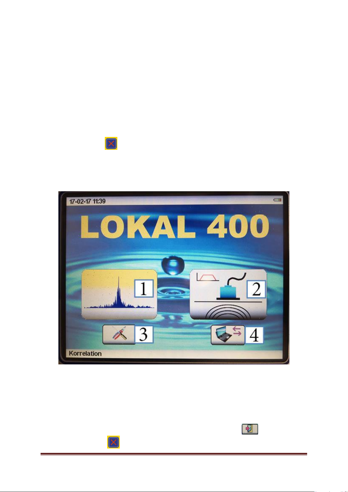
6.2 Main menu
As soon as the central unit has been switched on, the main menu is displayed offering the following selection
options:
[1]Correlationmeasurement
[2]Geophonemeasurement (electroacousticlistening)
[3] Settings
[4]DataexchangewithaPC
Ifyouwishtoleavetheselectedmenuandtogobacktothemainmenu,press intheuppercontrol
menuor the“Cancel” key .
Lokal 400Operating Manual Page 9
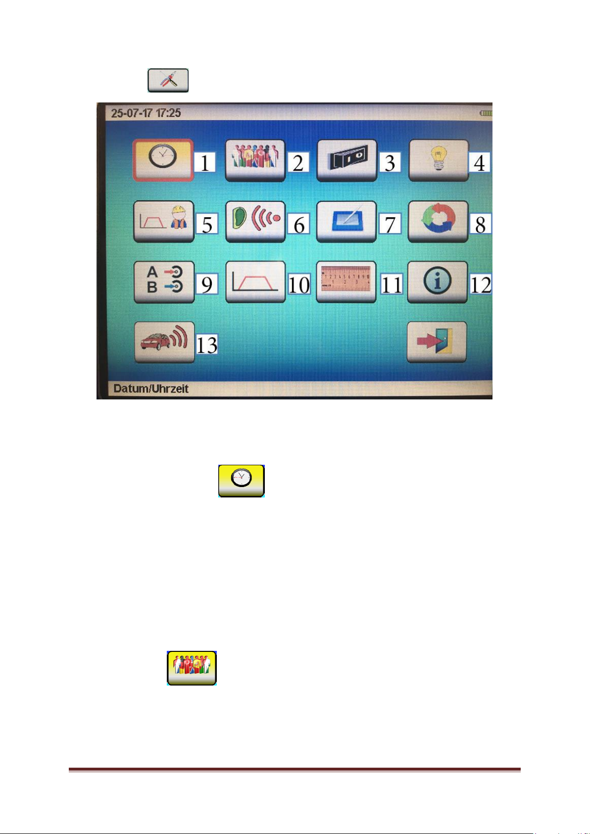
6.3 Settings
Themenusetting optionsarereachedthroughthesettingssymbolinthemainmenu.
Navigateto the requested setting option, select it, andsetyour requested configuration:
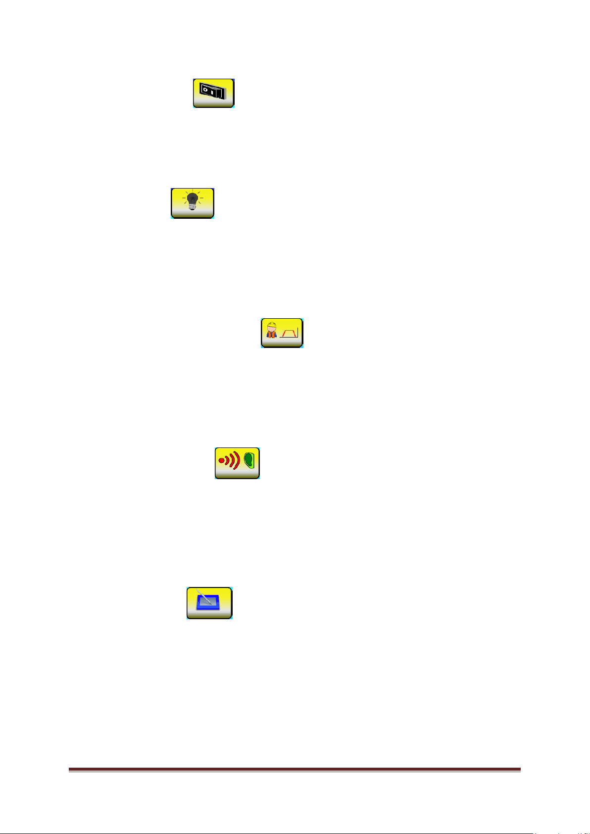
6.3.1. Date andtime of day [1]
Navigate to the “Date and time“ setting box with the dial. The selected setting box is now highlighted in
red.Confirmyourselectionbypressingonthedialtotheright.Theselectionisnowactivatedand willbe
highlighted in yellow. The settings can be changed by turning the dial (1-31 for the date; 1-12 for the
month,10-99 for theyear).Ifyouwishtoenterthedataon thetouchscreen,pleaseusethelowerfigure
box for the input. The input can be confirmed by tapping on the “OK” icon, and the input can be deleted
bytappingon “DEL”.
Please notethat you will have topressthe dialagainto confirmyour selection. Press the “Cancel” key if
you wishtocancelyourinput.
If you wish to confirm and leave the data you just entered, please press on the door icon. If you wish to
cancelall yoursettings andtoleavethesettingsmenu,pleasepressonthe”Cancel“ key.
6.3.2. Language [2]
The Lokal 400 system offers a number of display languages. Please scroll down until you reach the
languageyourequest andconfirmtheselectionofthislanguagebypressingtherightdial.
If you wish to leave the settings menu, please press on the “Cancel“ key or tap on the door icon on the
screen.
Lokal 400Operating Manual Page 10
6.3.3. Switch-off time [3]
Asthesystemisusuallyrunonbatterypower,itisreasonabletosavebatterycapacitywheneverpossible.
Therefore, the operator can set the time period when the device is switched off automatically unless in
use.Thisswitch-offtimerangesfrom1minuteupto60minutes. Thisfeaturesincreasesbatterylifeand
thustheoperating periodofthesystem.
Theconfigurationprocesscomplieswiththesettingprocessforthedateandthetimeofdayasdescribed
inChapter 6.3.1.
6.3.4. Lighting [4]
The brightness level for the display lighting can be adjusted individually on a scale ranging from
0% to 100%. The scale has two colored sections indicating the impact of the brightness level on the
energy consumption and thus on the battery’s operating period.
If the brightness level is chosen from within the green section, the operational period of the battery is
maximal.Theredsectionindicatesreducedoperatingtimeofthedevice.
The brightness can be changedby turning the right dial. The setting menu can be left either bypressing
thedial,orbypressingthe”Cancel“ key, or bytappingthedooricononthescreen.
6.3.5. Frequency range/Geophone [5]
Every acoustic leakage detection measurement mode offers two pre-selected filters (ground
microphone and testrod) and also a user-defined filter selection to be applied directly. These
settings can be determined in theFrequencyrangesetting menu.
High-pass filters (HP) and low-passfilter (TP) as well as the maximumrangeof the frequencyspectrum
can be adjusted. The maximum frequency range available for the geophone mode is 4,000Hz. The
configuration process complies with the setting process for the date and the timeof dayas described in
Chapter6.3.1.
6.3.6. Hearing protection [6]
The Lokal 400 leakage detection device features an automatic noise level absorber. This function
ensuresthattherequirementsforHearingProtection as perVBG121(VGB–GermanAssociation
of Institutions for Statutory Accident Insurance and Prevention) are fully met when operating the
original headphones (part of the delivery).Forindividualadjustmentofthenoiselevel,theLOKAL400
deviceoffersascalerangingfrom1(relativelylownoiselevel)to3(maximumnoiselevel),withanysetting
stillbeinginfullcompliancewithVGB121requirements.
Theconfigurationprocesscomplieswiththesettingprocessforthedateandthetimeofdayasdescribed
inChapter6.3.1.
6.3.7. Touch screen [7]
Withthis setting option, theoperator can de-activate thetouch screen, calibrate it,or runafunctionaltest
on the screen. Use the dial on the right to navigate to the requested selection field and confirm your
selectionby pressingthedial.
IfOn/Off hasbeen selected,thetouch screenfunctioncan be activatedandde-activated respectively by
pressing the dial. Please note that if the touch function has been de-activated any input can be made
throughthedialonly!
If the touch function of the LCD display does no longer work properly (e.g. a menu item can only be
selected by tapping beside the symbol), it may be necessarytocalibrate the touch function. If you need
todoso,pleasefollowtheinstructions as displayed andtaponthe spots as indicatedintheinstructions.
Afterthisreset,thetouchfunctionshouldworkproperlyagain.
Lokal 400Operating Manual Page 11
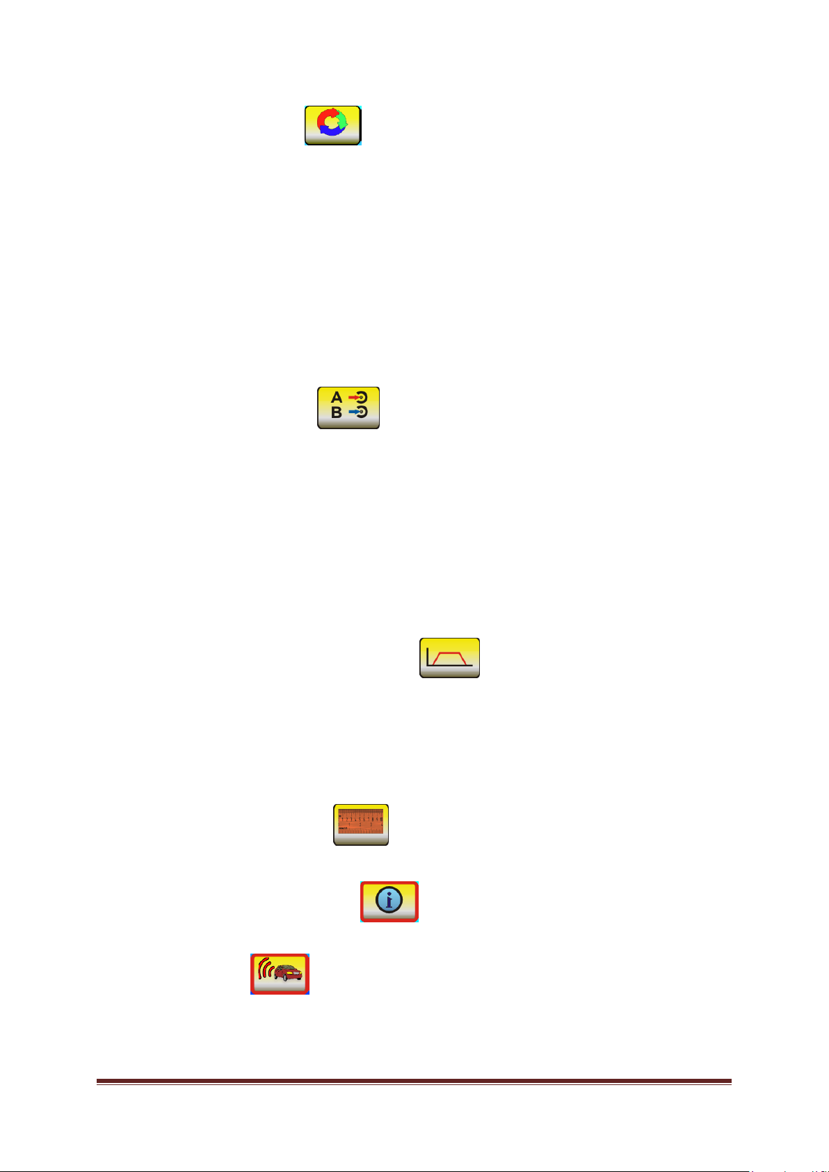
6.3.8.Clearingthememory[8]
Withthisfunction,theoperatorcandeletetwodifferentmemorystatesinthemeasurementdevice.
WithClearmemory, allmeasurementvaluessavedgloballyinameasurementdevicewillbe deleted.
WithResetparameters,alluser-specificsettingsforhigh-passfilters,low-passfilters,andthemaximum
rangeofthefrequencyspectrumassetintheFrequencyrangesettingmenu (seeChapter6.4.5) canbe
deleted.
Delete the memory directly by tapping on the touch screen or navigate with the right dial to the
selected setting menu and confirm your selection by pressing the dial. Successful deletion of the
memoryisindicatedwithatickbythesystem.
You can leave this setting menu either by pressing the “Cancel“ key or by tapping on the dooricononthe
screen.
6.3.9. Correlation entries [9]
Herethe signal entries canbeselectedtobeusedfor thecalculationof acorrelation.Thefollowing entry
combinationsareavailable:
- A-B
- A-C
- B-C
- A“Sensorentry“
- B “Sensorentry“
- C “Sensorentry“
A,B,andCarethechannelsofthemeasurementboxes(A=red;B=blue;C=yellow),and “Sensorentry“
indicates the direct connection of any microphone (see Chapter 5, Section ”Sensors“) to the Lokal 400
centralunit.
Thesesettingscanalsobemadethroughthecorrelationmainwindow.
6.3.10. Frequency settings/correlation [10]
Thismenuoffersthehigh-passfilterHP[Hz]andthelow-passfilterTP[Hz]aswellasthemaximumrange
of the frequency spectrum for the manual correlation measurement process. The maximum frequency
rangeavailableis5,000Hz.Theconfigurationprocesscomplieswiththesettingprocessforthedateand
thetimeofdayasdescribedinChapter6.3.1.
Thesesettingscanalsobemadeinthesub-menuformanualcorrelation.
6.3.11. Unit of measurement [11]
Twounitsofmeasurementareavailable:metric andimperial.
6.3.12. Information on the device [12]
Device-specificparameterssuchasfirmwareversionandserialnumberarelistedatInfo.
6.3.13.Transauto[13]
This function is to set the sensitivity limit for the interruption of a measurement process during the
correlation process. “0“ means off, “3“ means highly sensitive. For further information, please refer to
[Chapter7.5]
LOKAL 400OperatingManual Page12
7 Searching for a leakage by correlation
TheLOKAL400iscapableofcalculatingtheprecisepositionofa leakage(correlation).Inordertodoso,
please proceed as described in Chapter 5.1 “Powering-up for correlation“ and closely follow the hints
concerningthedifferenttypes ofsensor,themeasurementboxes,andthesignalentries.Ifyouintendto
start a correlation process, pleasetap on the correlation icon displayed or start the process with the dial
andthecorrespondingselections.
Basically,theLOKAL400deviceoffersa“manual“ correlation mode and an ”automatic“ correlation mode.
The “manual“ calculation requires analogue filters and signal amplification level to be defined by the
operator, whereas inthe ”automatic“ mode theLOKAL 400system selectssuchsettingsbyitself onthe
basis of certain algorithms. All settings concerning signal amplification and filter selection can also be
changed manually in any measurement mode in the correlation main window, i.e. there is the option to
readjusttheparametersmanuallyafter acertainmeasurementalsointheautomaticmode.
7.1 Automatic measurement
If you intend to carry out a measurement in the automatic mode, please tap on the automatic
measurement icon shown above. With this mode being selected, the correlation will always start in the
automaticmode[filtersandamplificationaresetbythesystem]inthecorrelationmainmask.
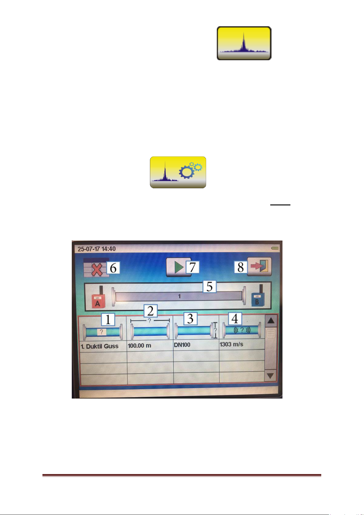
7.1.1 Entering pipe parameters
If the automatic measurement mode has been selected, the next window will display a table where the
pipe parameters such as pipe material [1], pipe length [2], and pipe diameter [3] need to be entered. As
soon as the relevant data has been entered in this line, the “Sound Velocity“ column [4] indicates the
assignedsoundvelocityforthispipesection.
The values are assigned in a table and saved in the device, but they can also be changed manually for
eachsectionsubsequently.This,however,isrecommendedforexperiencedoperatorsonly.Ifthesound
velocity was changed by mistake, it will be sufficient to change any parameter of the pipe and then to
resetit.Theassignedsound velocitywillthenbeindicatedinthecolumnagain.
LOKAL 400OperatingManual Page13
Up to 20 different pipe sections can be entered into the LOKAL 400 device. If a pipe consists of mixed
materials and/or features varying diameters, just enter the materials one by one into the table starting at
measurement box A (red). If you wish to delete any input, you can either press the button “line“ [6]
orselect ” ---“ as thepipematerial.
Whenallpipesectionmaterials havebeenenteredcorrectly,pressingthePLAYbutton[7] will
make the main mask of the correlation appear (see main illustration in Chapter 7.3 “Setting options for
correlation”). Pressing the door button [8] makes the system return to the main menu. If you press the
“Cancel”key(“X“),thesystem willgo backtothe windowwhere youcan choosebetweentheautomatic
and themanualmeasurementmodes.
7.1.2. Starting the correlation
Once the “Play”button has been pressed, the LOKAL 400 device will start automatically to adjust the
noise level amplification for the two channels (A [8 and 8.1] and B [12 and 12.1]) so that the noise level
optimal for the measurement process is available to the system. This is also indicated through the
adaptation of the amplification level [8.1 and 12.1] displayed at the lower edge of the correlation main
window.
He LOKAL 400 system will then carry out some test measurements with different filter settings [10] to
determinetheoptimalnoisequalityofthetwosignals [9]and[10] andofthecoherence[10]respectively.
This is indicated by the number of average determinations [13] rising briefly, being canceled, and then
beingcountedupagainwiththenextfiltersetting[10]. Afterashortwhile,theLOKAL400devicewillthen
start on the proper measurement procedure and will determine the exact position of the source of the
noise. When the measurement has been completed, the number of average determinations stops
counting up [for the automatic mode, a total of 50 average determinations has been set ex works]. The
current measurement procedure can be interrupted anytime by tapping on the “Stop”icon
(displayedinfield[1]duringthemeasurementprocess).Thedetectedsourceofthenoise,whichisusually
theleakagespot,[seeChapter 14 “Troubleshooting“] willbedisplayedintheupperimage[6]asasymbol,
and the corresponding distance between the leakage spot and microphone A and microphone B
respectivelywill beindicated.
7.2 Manual measurement
If you wish to carry out a measurement manually, please tap on the “Manual measurement” icon (as
shownabove). Awindowwillappear whereyouneedtoentersomedatasuchasthepipematerial,pipe
length, and pipe diameter. Then proceed as described in Chapter 7.1.1 “Entering pipe parameters“ for
the automatic measurement mode. When all pipe parameters have been entered correctly, tap on the
“Continue“ button togettothemenuwherethefiltersneedtobeset(seeChapter
7.3.1 “Filter settings”). The main image will show the coherence of the last measurement. Now please
setthehigh-passfiltersandthelow-passfiltersinaccordancewiththefrequencydistribution.In addition,
the corresponding noises delivered through Channel A and Channel B can be listened to by activating
the headphones connection. So the operator can assess which filter setting provides the optimal noise
quality.
Clickon the “Continue“ button to reach the correlation main window (seeillustrationinChapter7.3“Setting
options for correlation”). In contrast to the automatic mode, the measurement procedure will not start
automatically in the manual mode. The system requests the noise level amplification for Channel A [8]
and Channel B [12] to be adjusted in the main window. The same applies to all other signal entries.
LOKAL 400OperatingManual Page14
Tappingonthelevelmakesanotherwindowopenwhereyoucanadaptamplificationtoalevelbetween
0 and100%. Pressing thedialortappingonthedeviceoutsidethewindowwillclosethissub-menu, and
the set amplificationlevel will be displayed belowthenoise level. Theappropriateamplification level has
been selected if the medium noise level fills about the half of the noise level indicator. The noise can be
listened to with the headphones and thus can be checked if the signal intensity is too low or if the signal
isoverdriven.
When all input has been entered, the correlation can be started by tapping on the “Play” button [1]
. The number of average determinations is counted up, and the correlation peak should start
forming. The measurement processcan be interrupted anytime by tapping on the “Stop”icon
locatedintheupperrightcorner. Themeasurementprocedurewillrunupto250averagedeterminations
in the manual mode unless the measurement is interrupted beforehand. Usually 40 to 50 average
determinations are sufficient to receive a proper result. If the result is not satisfactory, you may have to
checkandtoadjustthefiltersettings,amplification,orthemeasurementset-up.
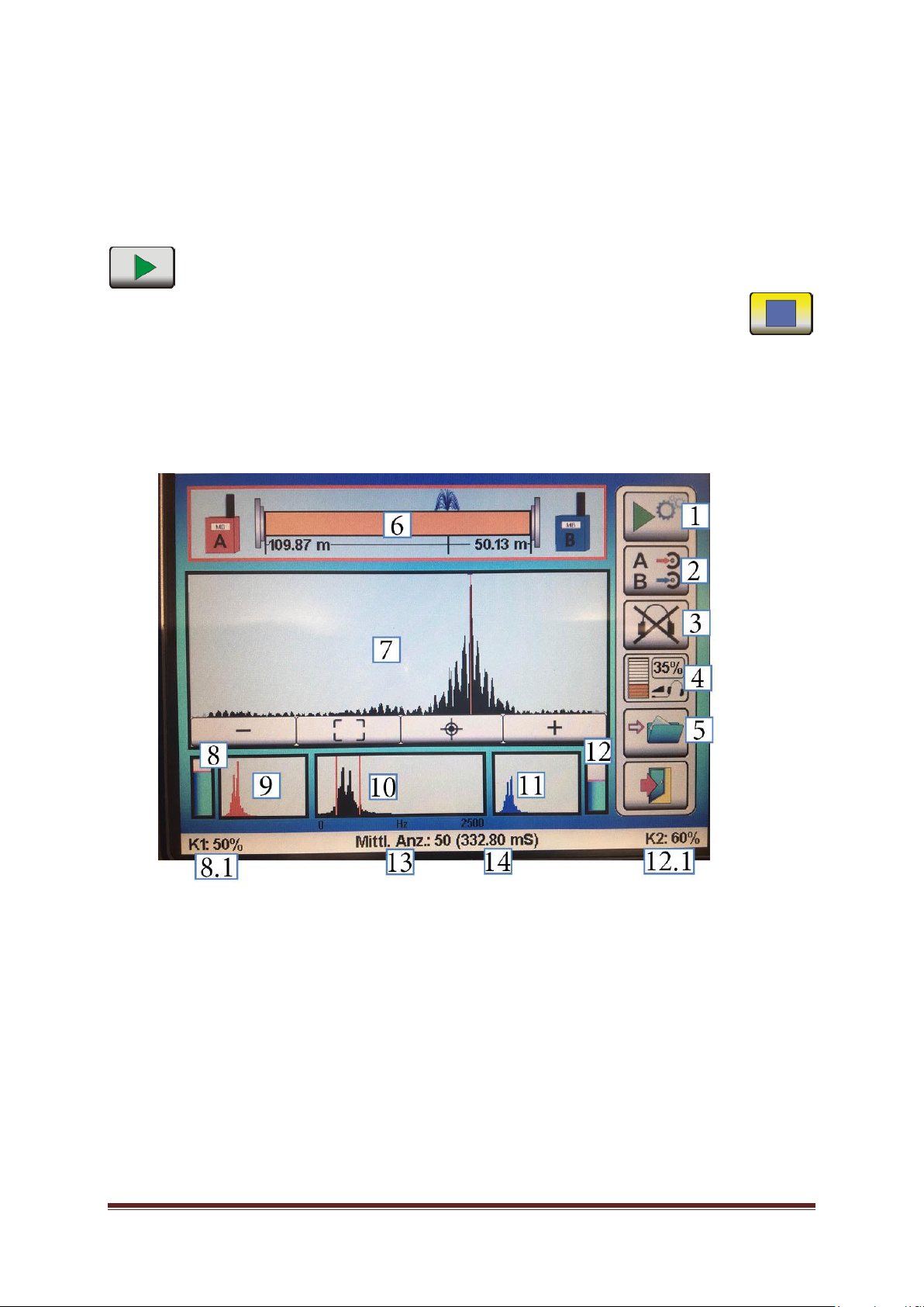
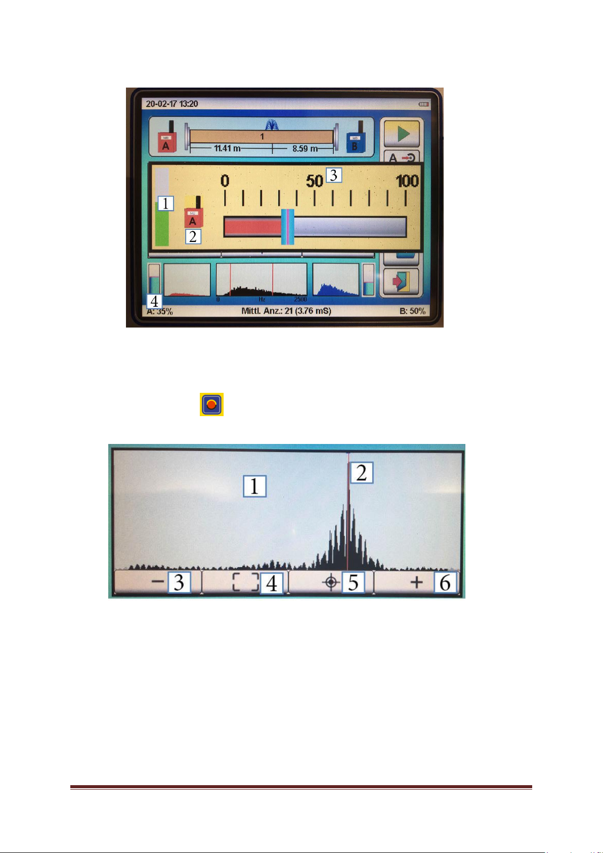
7.3. Setting options for correlation (correlation main window)
Thecorrelationmainwindowoffersthefollowingoperatingelements:
[1]Start/Stopofameasurement
[2]Switching betweendifferent signalentries
[3]Headphone jack for differentsignalentries
[4] Headphonevolume
[5]Savingthemeasurement
[6]Indicationofpipelinerupturesymbolicallyandnumerically&active buttonformaterialinput
[7]Correlationresults
[8]AmplificationChannelA [8.1]numericalvalue(0-100%)toamplifyChannel A
[9] Frequency illustration (FFT)for Channel A
[10]Coherence(FFT)forA and B
[11]Frequency illustration(FFT)forChannel B
[12]AmplificationChannelB [12.1]numericalvalue(0-100%)toamplifyChannelB
[13] Numberofcompleted averagedeterminations
[14]DELTA T inmilliseconds
LOKAL 400OperatingManual Page15
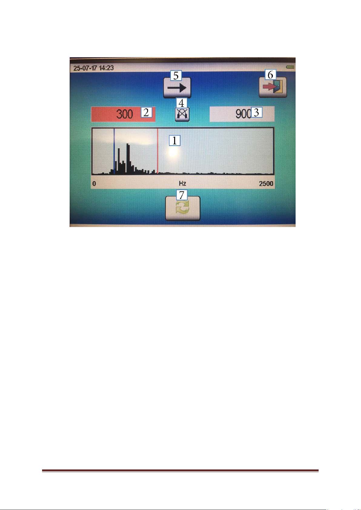
7.3.1. Filter settings
You will reach the filter setting mask either through the selection process of the manual measurement
mode in the second setting step or through the correlation main window by selecting the filter setting
options [10] by tapping on the touch screen or by applying the dial. A new window (as shown above) is
displayed,andthefollowingfunctionsareofferedtotheoperator:
[1]CoherenceimageofbothsignalsA and B
[2]Settingsforthehigh-passfilter(HP)
[3]Settingsforthelow-passfilter(TP)
[4]Activatingtheheadphonejack or Switching theheadphonejack betweenChannel Aand
ChannelB
[5] “Continue“ button
[6] “Back“ button
[7]Updating thecoherenceimage
In this filter selection menu, the coherence image [1] is always displayed as the result of the last
measurement procedure. Therefore, itisrecommendedtomakethesystemre-calculatethecoherence
image throughthe function [8] before the filters are set again to have the current coherence displayed. If
you press the “Update” button,itmaytakeseveralsecondsuntilthenewimagehas beencalculated.
The filter levels can be adjusted by selecting the appropriate high-pass filter [2] and low-pass filter [3]
fields.Thesetfiltersaredisplayedinthecoherenceimageasadditionalredlines.Ifthehigh-passfilteror
the low-pass filter has been selected, the line turns blue in the image and the box is highlighted in red.
Nowthefilterselectioncanbe changedbytappingonthe imageorbyapplyingthedial.
Press the “Continue“ button[6]ifyouwishtoreachthecorrelationmainwindow. If you tap on the “Back“
button [7], the subsequent window to be displayed depends on whether you reached the Filter settings
windowviathesecondsettingstepinthemanualmeasurementmodeorviathecorrelationmainwindow.
In the first case, the system will go back to the start screen; in the latter case, the system will goback to
thecorrelationmainwindow.
LOKAL 400OperatingManual Page16
7.3.2. Signal amplification
If you wish to set the amplification level of the corresponding entries, please tap on the ”Level“ button [4]
in the correlation main window. A new window is opened up where you can adjust the requested
amplification levelwiththedialorwiththetouchfunction.
NOTE:Amplifythenoiselevelsothatthebarofthenoiselevelindication[1]fillsabouthalfoftheindication
box.
TIPP: If you press on this button in the window or on the “Measurement box” button [2], the
LOKAL400system will automaticallyadjusttheamplificationlevel.
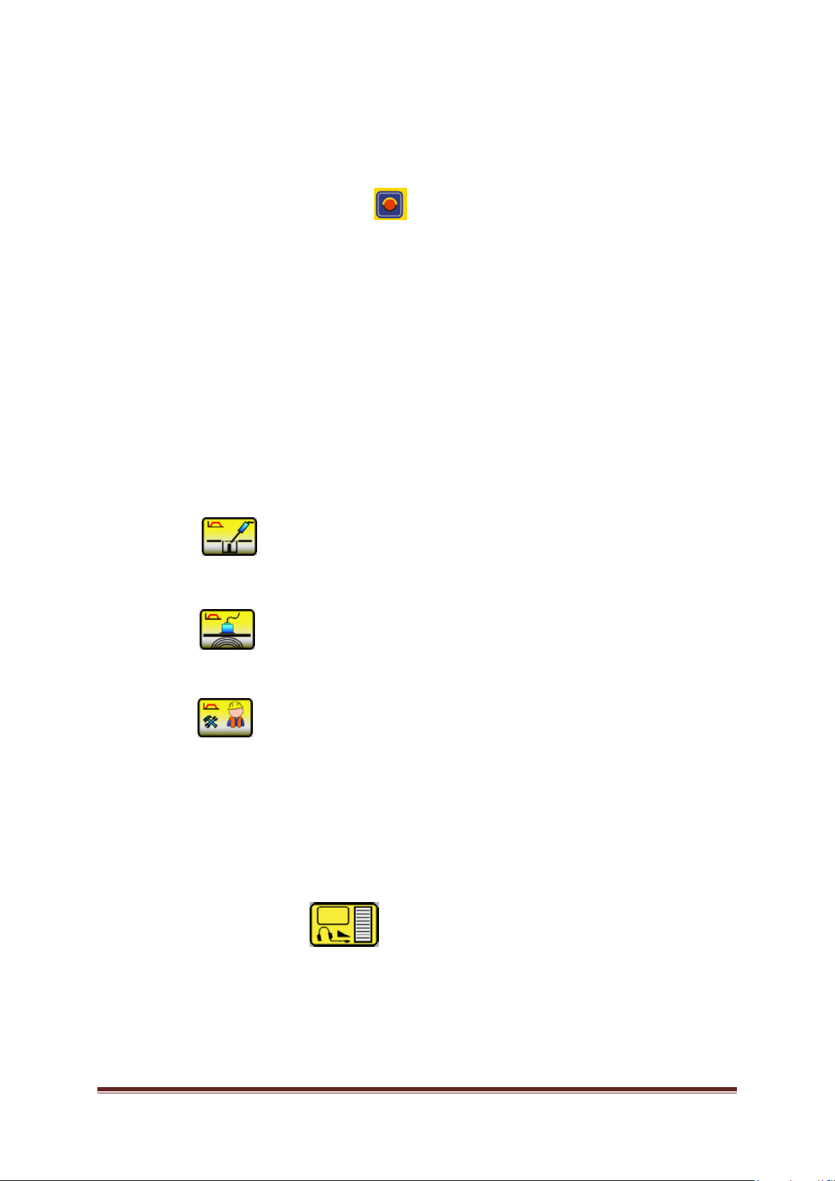
7.3.3. Correlation results
Ifameasurementisstoppedeitherafterthemaximumaveragedeterminationshavebeencompleted(50
determinationsintheautomaticmodeand250determinationsinthemanualmode)orbytappingon the
“Stop”buttonduringameasurement procedure,thesystemallows navigating inside thedisplayedresult
imageby selecting the correlationresultwiththedial or bytapping onthebutton. Insidethe window, the
followingselectionoptionsareoffered:
[1] Correlation imagebetween signal Aandsignal B
[2]Correlationpeak(red line)
[3]Zoomingout
[4] Displaying the entireimage
[5]Zoomingin
[6]Searchingforthemaximumvalue

LOKAL 400OperatingManual Page17
If the correlation image [1] is chosen with the touch function or by pressing the dial, the correlation peak
(red line)canbeadjustedwiththedialor withthetouchfunction.
Once a measurement procedure has been completed, the correlation peak is automatically set to the
maximum. If the operator wantstoknow if there is apossible second peak, the system offersa function
to find out about a second peak. If the line is moved with the dial, the position has to be confirmed by
pressing the dial again to make the system display the new distances in the “Pipe rupture” image (see
Chapter7.3.[6]).Withthetouchfunction,thenewdistance isdisplayeddirectly.
7.3.2 Saving/uploading a measurement
A measurement can be saved with the ”Filing“ button (as shown above) located in the correlation main
window.Asafirststep,youneedtodeterminethefolder wherethemeasurement hastobesaved. The
filewillbesavedbythesystemwiththecurrentdateandtimeofday. The device iscapableofsaving up
to 100 correlations. When the memory capacity is exhausted, it is recommended to save the data on a
PC. Old data can be overwritten, or you can delete the entire memory with the “Delete memory“ button
inthesettingsmenu[seeChapter6.3.8].
If youwishtouploadameasurement,gobacktothestartscreenand select ”Correlation“ .
Select the “Folder“ button in the next picture. Now a new window appears containing the list
withallsavedcorrelations.Ifyouchoosealineandconfirmyourselectionbypressingthedial,thesystem
willtakeyoudirectlytothecorrelationmainwindowwherethesavedresultwillbedisplayedandthepipe
parameters(length,material, diameter)canbechanged.
7.4 Receiving radio data
The system indicates throughthe two icons to the right and to the left of the pipe rupture indication [see
Chapter7.3[6]] whetherornot the dataissuedbyatransmitter(measurement box) isbeingreceivedby
theLOKAL400centralunit.Ifthedataisbeingreceived,theiconsaredisplayedasshownintheexample.
If datareceptionis interrupted[forpossiblereasonspleaseseeChapter11“Troubleshooting“],the icons
arecrossedwith ablackX.
NOTE: If data reception is interrupted during a measurement process, the measurement is stopped
automaticallyand will not becontinuedunless datareceptionhasbeen restored.
7.5. Transauto function
Transautofunctionsensitivity is adjustedasdescribedin”Settings“[see Chapter 6.3.13.Transauto].The
transauto function is always activated and can only be de-activated by setting the sensitivity to ”0“. The
function provides the operator withexcellentcorrelation resultseven ifthemeasurement is carriedout at
a noisy spot with changing disturbing noises such as a busy street. The system automatically interrupts
themeasurementprocessifadisturbingnoisedrownsouttheactualleakage-bornenoiseandcontinues
themeasurementassoonasthesourceofthedisturbingnoisehasdisappeared.
NOTE:Ifthetransautosensitivityhasbeensettoanexcessivelyhighlevel,itmayhappenthatthesystem
is not capableof carrying out any measurement procedure withtheactual settings attheparticular spot.
In such case, the sensitivity needs to be reduced or even set to “0” (de-activated), or the measurement
hastobecarriedoutatanotherpointoftimewhenthedisturbingnoiselevelislower.

LOKAL 400OperatingManual Page18
7.6 Calibration of sound velocity
In rare cases, it might happen that the sound velocity of the pipe-section is not the same than the one
storedintheLokal400.Thereasonfor thiscouldbetheageofpipelines(i.e.hardeningofthematerialin
plasticpipes)orincrustations(i.e.corrosiononductile orironpipes).Thesameproblemisfacedifrepairs
with different materials were not mapped or recorded (often not the same material gets used!!). A
difference in sound velocity is elaborate for the result of the correlation and could lead to miss digging in
the worst case. One option to check the sound velocity on the section of pipe you want to conduct the
measurementistocalibrateit.Pleaseapplyfollowing procedure:
1. Open outside of the measurement section a hydrant or wash out (or similar). Means, “behind” A
or B. Important: the sound needs to be greater than the leak noise itself. [Perhaps through new
positioningoftheMB´s,thenoisefromtheleakitselfcouldbeusedtocalibratethesoundvelocity
forthesection]
2. TypeinthepipeparametersforthesectionintotheLokal400[refertosection7.1.1]
3. Startacorrelationandwaituntilaresult(peak)isshown
4. Because the (main-) noise is now outside of the measurement section (between A and B) the
Lokal 400 will show a “leakage” directly on A or B (depending which one is nearest)
5. Nowyoucancalibratethesoundvelocityofthemeasurementsectionthroughpressinglongonto
this button . A multiple piep- tone will be audible. You will find the “calibrated” (new) sound
velocityinthepipeparametersettings[seesection7.1.1]
IMOPRTANT: Thisonlyworks, if onlyonesection is entered inthe pipe parametersettings. As soon as
moresections aretypedin,itdoesnotwork!
NOTE:Ifyouchange anything on the pipe parameters (i.e. dimension or material), the “calibrated” sound
velocitywillbedeletedandthestoredvelocitywillbetakenoverautomatically.Itmakessensetosafethe
calibrationfileforfuturemeasurementsonthissectioninthedevice.

LOKAL 400OperatingManual Page19
8. Acoustic leakage detection
Theacousticleakagedetectionmenuiscalledbytappingonthissymbol.
The following parameters can be set as per a uniform operating scheme in any of the two operating
measurement modes available for acoustic leakage detection irrespective of the actually set
measurementmode.
[1]Adjustingthesensitivityofthesensor
[2]Selectingthefiltersetting
[3]Adjustingthevolume(headphones)
[4]Selectingthesensors (filter pre-selections)
[5[ Selectingthemeasurementmode
[6]Saving ameasurement
[7]Uplopading ameasurement
8.1 Setting the acoustic parameters
8.1.1 Adjusting the sensitivity of the sensors
Ifyouwishtoadjustthesensitivityofthemicrophoneconnectedtothemeasurementdevice,pleasenavigate
in themeasurement indication windowto the symbol for sensor sensitivity setting (1). Activate the symbol
andconfirmyourselection.Thewindowwherethesensitivityof thesensorcanbeadjustedwillopenup,
and a scale ranging from 0 to 100% will be displayed where the currently set amplification of your
LOKAL 400OperatingManual Page20
microphone is displayed.Amplificationcanbeadjustedbyturningthedialorbydrawingthescalebarwitha
fingeronthetouchscreentotherequestedsensitivitylevel.
Youhavesettheoptimalsensitivitylevelassoonasthecontrolbar(2)displayedintheleftpartofthewindow
levelsoutatabout50%.
PressingthedialorpressingtheAmplificationiconagainactivatesthesetamplificationlevel.
TIP:Iftheamplificationmenuiscalledand ifthis buttonispressedforalittlewhile,theLOKAL400system
willchoosetheoptimalamplificationlevelautomatically.Assoonastheoperatorhearsseveralbeepswhilethe
buttonispressed, the buttoncanbereleasedand thesystemwillchoosethemostsuitableamplificationlevel.
ATTENTION: thesensorhastobepositionedatthespotwherethenoiseistobepickedup.
NOTE: Assoonasthesensitivitylevelischanged,thecurrent measurementseries will bedeleted!
8.1.2 Setting the sensor selection (filter pre-settings)
The system offers three pre-defined filter settings for acoustic leakage detection. In addition, every filter
rangecanbechangedindividuallyduring ameasurementprocedure:
If you wish to select any of the three pre-defined filter settings, please navigate in the measurement
indication window to the filter mode symbol (1), activate the symbol, and confirm your selection. The
windowwherethefilterpre-settingscanbeselectedwillopenupnow.
Threepre-settingsareavailable:
Fittings(2)
A frequency range of 0to2,000 Hz is pre-defined, witha high-pass filterof 200 Hzand a low-pass
filterof 800Hz.Thissetting isoptimalforlisteningtofittingsandhydrants.
Ground(3)
A frequency range of 0 to 1,000 Hz is pre-defined, with a high-pass filter of 50 Hz and a low-pass
filterof 400 Hz.Thissetting isoptimalforlisteningtosurfaces.
Operator(4)
Thispre-setting usesthefilter range youhavepre-setaccording toyourpersonalfilter preferences inthe
settings menu at Frequency range Geophone (see Chapter 6.3.5). The system comes with a standard
pre-setfrequencyrangeof0to1,250Hz,withahigh-passfilterof100Hzandalow-passfilterof800Hz.
The pre-set filter frequencies can be adjusted individually anytime and in any measurement mode
betweenthesingleacousticleakagedetectionmeasurements.Forfurtherinformation,pleaserefertothe
instructionsasstatedinChapter8.4.
NOTE: Assoonasthefiltersetting ischanged,thecurrentmeasurementserieswillbedeleted!
8.1.3 Adjusting the volume
You can adjust the volume for the headphones subject to the pre-set hearing protection level (see
Chapter6.4.6.).
Thecurrentlysetvolumeisindicatednumericallyandalsoasabarchartinthesymbolfortheheadphone
volumesetting (1) located inthe measurement indication window.
Table of contents
Other Fast Measuring Instrument manuals


