Epever MT75 User manual
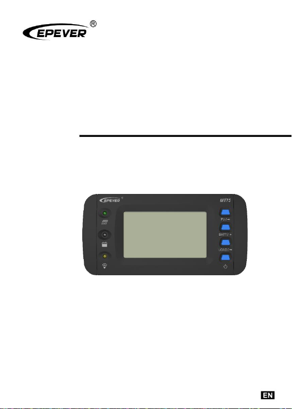
Remote Meter
USER MANUAL
MT75


Contents
1. Safety Instructions................................................................1
2. Overview ..............................................................................2
3. Appearance ..........................................................................3
4. Accessories ..........................................................................5
5. Installation Instructions .........................................................6
6. Indicator Instruction ..............................................................8
7. Button Instruction..................................................................9
8. LCD Display .........................................................................10
9. Error Codes..........................................................................12
10. Specifications .....................................................................14
11. Dimension ..........................................................................16
12. Recommended Applications................................................17
12.1 Standard Application....................................................17
12.2 Upgrade Application ....................................................18
12.3 Advanced Application ..................................................19
12.4 Pro. Application ...........................................................20


1
1. Safety Instructions
Please keep this manual for future reference.
Please read this manual and safety information carefully before
using the product.
Keep the product away from rain, exposure, severe dust,
vibration, corrosion, and intense electromagnetic interference.
Please avoid water, and other liquids enter into the product.
There are no user-serviceable parts inside the product. Do not
disassemble or attempt to repair it.

2
2. Overview
MT75 is a new generation of remote meters that can monitor the
EPEVER solar charge controller and inverter on one screen
simultaneously. This product provides multiple solutions to fit different
requirements from off-grid users.
Features:
Dual RJ45 communication ports
4.7-inch LCD screen, real-time dynamic display of system data
Visually error codes, timely notification of warnings and faults
Load ON/OFF button to control the load output directly
Dry contact output and enable switch design
Remote control inverter ON or OFF
Friendly connect with different EPEVER devices
3
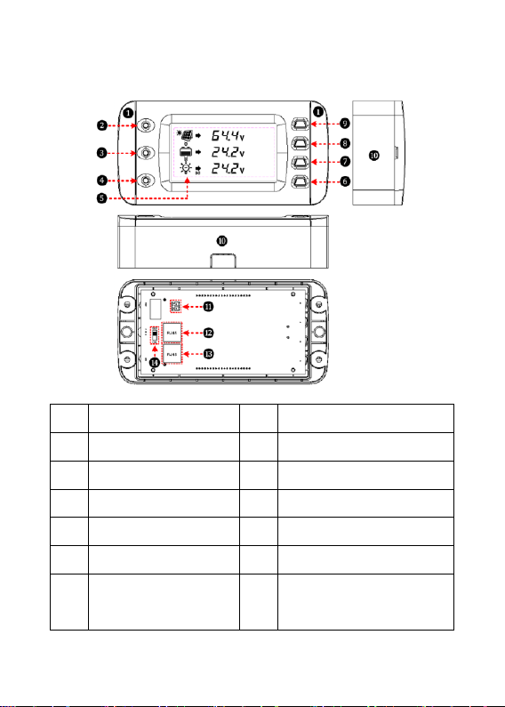
3. Appearance
❶
Decorative shell
❽
Battery parameter button
❷
PV indicator
❾
PV parameter button
❸
Battery indicator
❿
Base (optional)
❹
Load indicator
⓫
Dry contact interface①
❺
LCD
⓬
RS485 port 1(RJ45)
❻
Load ON/OFF button
⓭
RS485 port 2(RJ45)
❼
Load parameter
button
⓮
Dry contact
enable switch ①
4
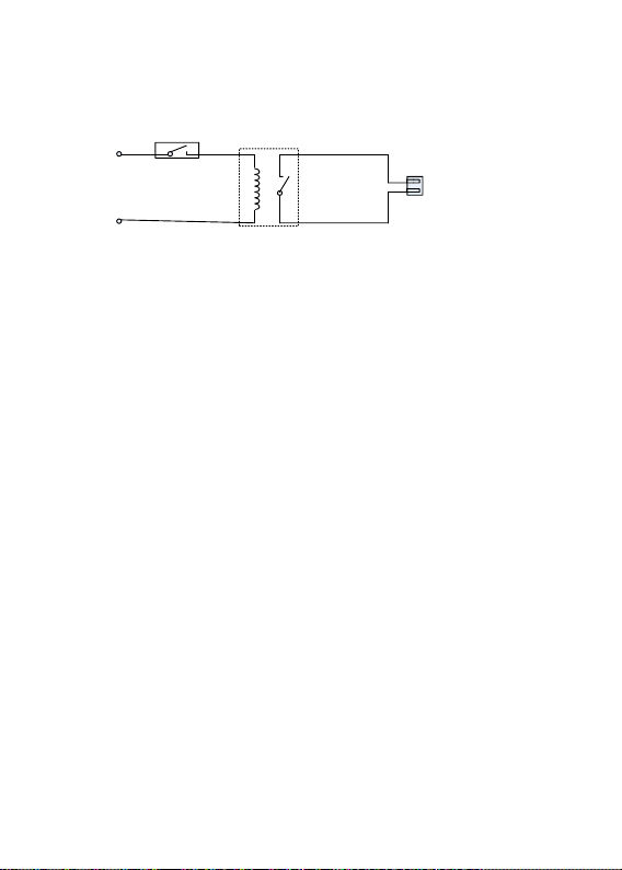
①Working Principle:
Dry
contact
Dry contact
enable switch
+5V
GND
Dry contact
Interface
Dry contact rated value: 5A/30VDC; Max. value: 0.5A/60VDC
Note: Turn the dry contact enable switch⓮ to ON only when the dry
contact is used, and turn it OFF when not used to save the dry contact's
loss.

5
4. Accessories
Category
Name
Number/Model
Purpose
Included
2P-3.81 plug
2 pcs
Connect to the
3.81 pins remote
control switch of
inverter
RS485 cable
2 pcs/CC-RS485-
RS485-200U
Connect the
MT75 to the RJ45
port of the
controller or
inverter
MT75 base
1 pcs
Used for wall
installation
Optional
RS485 cable
CC-RS485-
RS485-
50/100/200/300/50
0/1000U
(0.5/1/2/3/5/10
meter)
Connect the
MT75 to the RJ45
port of the
controller or
inverter
USB cable
USB-RS485-200U
Connect the
MT75 to the PC
3.81-RS485
cable
3.81-RS485-200U
Connect the
MT75 to the
iTracer-AD series
and the iTracer-
ND series
controllers
Dry contact
interface
cable
C-2P3.81-2P3.81-
50/100/200/300/50
0/1000U
(0.5/1/2/3/5/10
meter)
Connect the 3.81
plug
6
5. Installation Instructions
Before Installation
1. Check whether the solar controller's ID is 1; if not, set it to 1.
2. Check whether the ID of the inverter is 3; if not, please set it to 3.
3. Wall installation or surface mounting installation is optional.
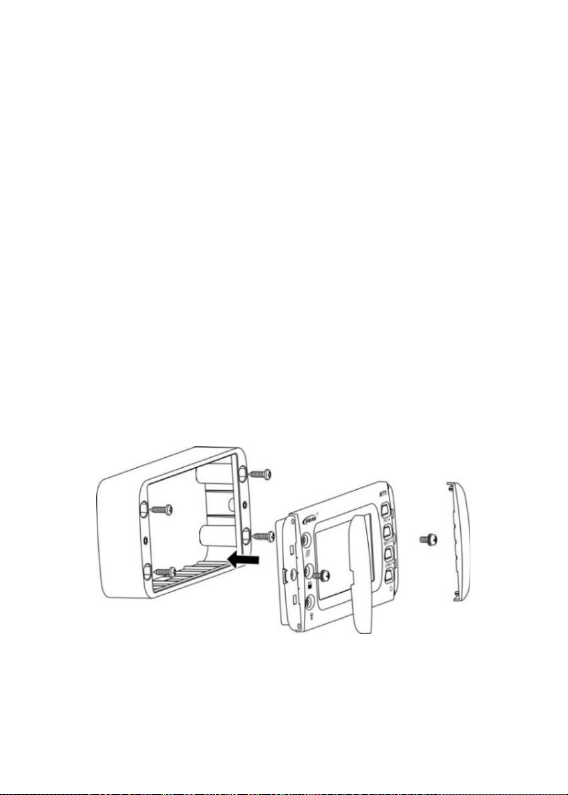
Wall Installation
Step 1: Locate and drill screw holes based on the frame mounting
dimension (175x50mm), and erect the plastic expansion bolts.
Step 2: Use four M5 self-tapping screws to fix the frame.
Step 3: Remove the decorative shell.
Step 4: Use two M4 pan head screws to mount the MT75 surface on
the base.
Step 5: Install the decorative shell.
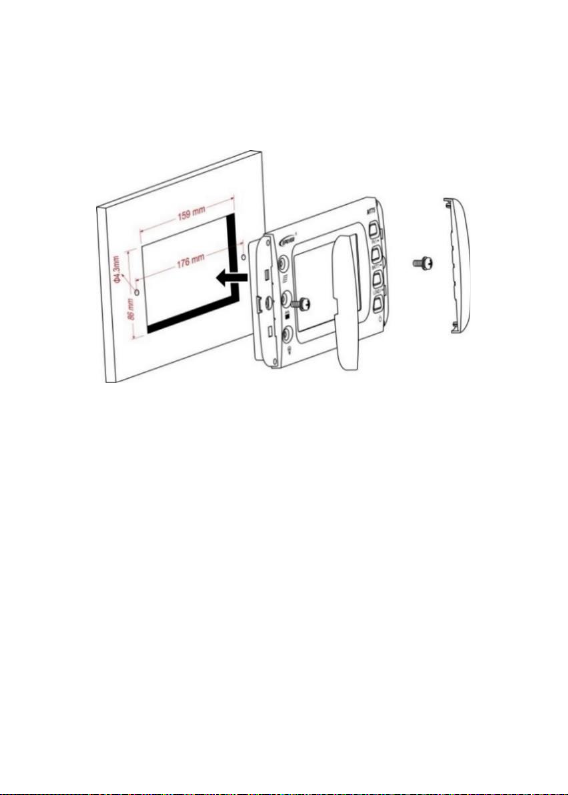
Surface Mounting Installation
Step 1: Locate based on the installation size (176mm) and drill screw
holes (no smaller than 158.2x85.2mm).
7
Step 2: Remove the decorative shell.
Step 3: Use two M4 pan head screws to fix MT75.
Step 4: Install the decorative shell.
8
6. Indicator Instruction
Indicator
Color
Status
Instruction
Green
ON solid
PV is charging
Green
OFF
No PV charge
Green
Fast
flashing
PV overvoltage
Green
ON solid
Battery normal
Green
Fast
flashing
Battery overvoltage
Orange
ON solid
Battery under voltage
Red
ON solid
Battery over-discharge
Red
Slow
flashing
Battery over temperature
Battery under temperature
Controller over temperature
Green
ON solid
Load switch ON
Green
OFF
Load switch OFF
Green
Fast
flashing
System voltage error
Orange
Fast
flashing

9
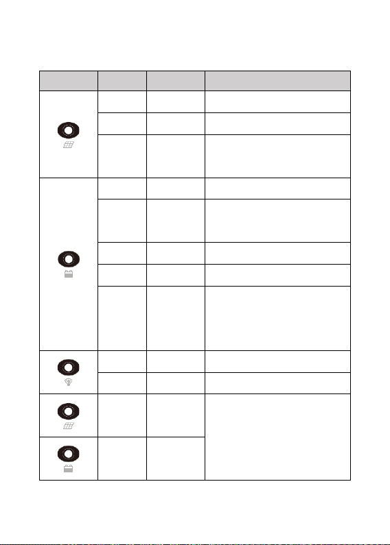
7. Button Instruction
Button
Operation
Instruction
Click
Display PV parameters in cycle
Click
Display battery parameter in cycle
Click
Display load parameter in cycle
Exit the fault page
Press for 5S
Check error code information
Click
Control the switch of solar controller
and inverter in sync①
Press for 5S
Clear the total of PV generated power,
total DC load usage, and total AC load
usage
①When the solar controller and inverter's output is out of sync, click to turn off
all the loads' output simultaneously, click again to turn on all the load outputs.
10
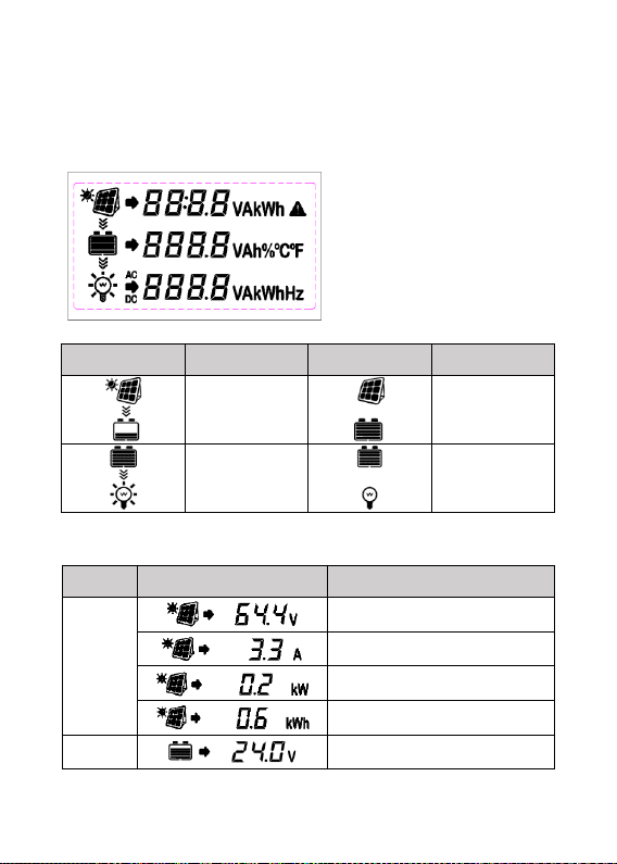
8. LCD Display
LCD Display
Symbol
Definition
Symbol
Definition
PV
charging
PV
no charge
Load ON
Load OFF
LCD Display Interface
Item
LCD Display
Definition
PV
PV voltage
PV current
PV power
Total PV generated power①
Battery
Battery voltage
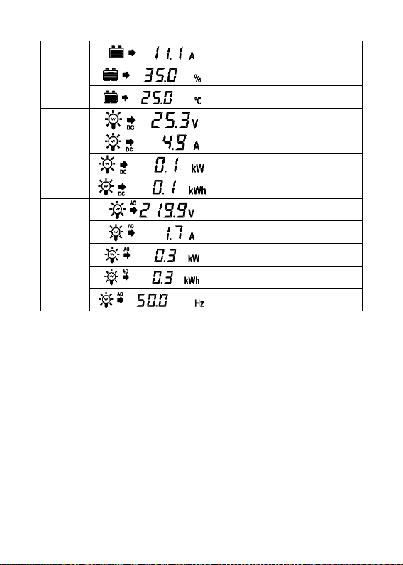
11
Battery current
Battery capacity
Battery temperature
DC
Load
DC load voltage
DC load current
DC load power
Total DC load usage①
AC
Load
AC load voltage
AC load current
AC load power
Total AC load usage②
AC load frequency
①The "Total PV generated power" and "Total DC load usage" is the solar
controller's parameter, which can be directly read and displayed by the
MT75.
② The "Total AC load usage" is calculated based on the inverter's AC load
power and displayed on the MT75.
12
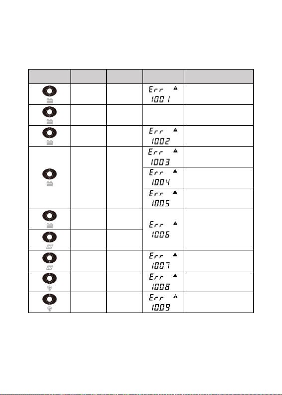
9. Error Codes
Solar Controller Error Codes
Indicator
Color
Status
LCD
Code
Green
Fast
flashing
Battery over
voltage
Orange
On
solid
——
Battery under
voltage
Red
On
solid
Battery over-
discharge
Red
Slow
flashing
Battery over
temperature
Battery under
temperature
Controller over
temperature
Orange
Fast
flashing
System voltage
error
Green
Fast
flashing
Green
Fast
flashing
PV overvoltage
Green
Slow
flashing
Load short circuit
Green
Slow
flashing
Overload
Note: When the battery voltage is equal to the low voltage disconnect
voltage (LVD) point of the controller, the controller and inverter's
output will be turned off.

13
Inverter Error Codes
Indicator
Color
Status
LCD
Code
Green
Slow
flashing
Output short
circuit
Output overload
Output voltage
abnormal
Busbar
overvoltage
Input overvoltage
Input under-
voltage
Input over-
current
Inverter over
temperature

14
10. Specifications
Model
MT75
Compatible
products
Controller
XTRA-N series/TRIRON series/
Tracer-AN series/Tracer-BN series
Note: Required cables for the above
products are shipped with MT75.
iTracer-AD series/iTracer-ND series
Note: Required cables for the above
products need additional purchase.
Inverter
IPower series(1kw or above, suitable for
application 1/3)/IPower-Plus series/
NPower series/SHI series
Input power
5VDC(Power supply by the connected controller
or inverter)
LCD visual
angle
12' clock
LCD
backlight
Yes
Installation
methods
Wall installation
Surface mounting installation
Self-
consumption
14mA/5V(no backlight)
26mA/5V(backlight)
Max. power
consumption
100mA/5V(Backligh+dry contact)

15
Working
temperature
-20℃~+65℃
Storage
temperature
-20℃~+80℃
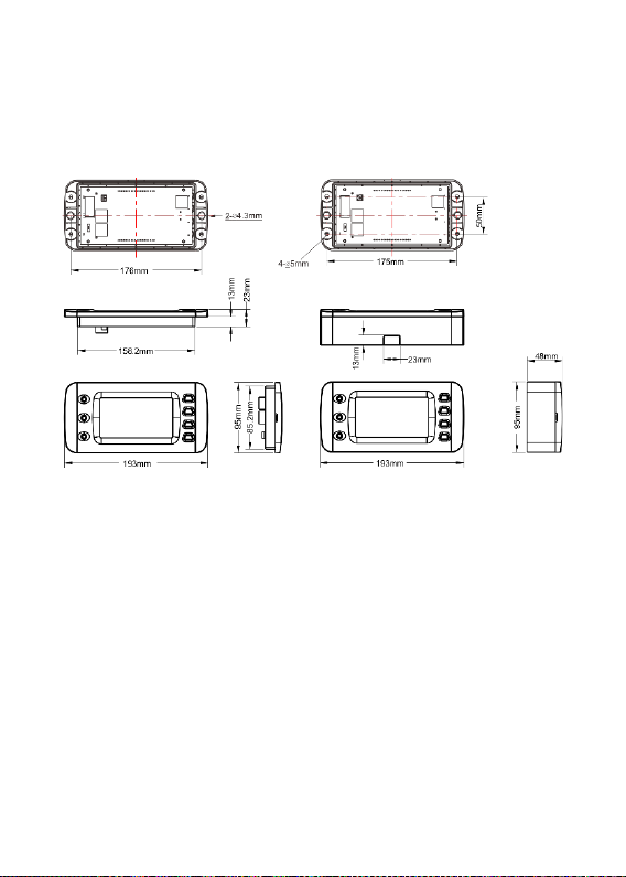
Dimension
193×95×48mm(base)
193×95×23mm(no base)
Mounting
size
175×50mm(base)
176mm(no base)
Mounting
hole size
φ5mm(base)
φ4.3mm(no base)
Net Weight
0.29Kg(base)
0.22Kg(no base)
16
11. Dimension
Dimension without base Dimension with base
Other manuals for MT75
1
Table of contents
Other Epever Measuring Instrument manuals


