Epever MT91 User manual

Remote Meter
USER MANUAL
MT91


Contents
1. Safety Instructions..........................................................................1
2. Overview ........................................................................................2
3. Appearance ....................................................................................3
4. Installation Instructions ...................................................................6
5. Button Instruction............................................................................7
6. Real-time Interface .........................................................................8
7. Setting Interface .............................................................................9
8. Error Codes....................................................................................13
9. Specifications .................................................................................14
10. Dimension ....................................................................................15


1
1. Safety Instructions
Thanks for selecting the MT series; please read this manual carefully before
using the product.
Please keep this manual for future reference.
When you receive the product, check whether there is any damage that
occurred in transportation. Contact the transportation company or our
company in time for any problem.
Please read this manual and safety information carefully before installing it.
Keep the product away from rain, exposure, severe dust, vibration,
corrosion, and intense electromagnetic interference.
Please avoid water, and other liquids enter into the product.
There are no user-serviceable parts inside the product. Do not disassemble
or attempt to repair it.

2
2. Overview
MT91 is a new generation of remote meters specially designed for the
EPEVER inverters. It displays the real-time parameter of the inverter on one
screen. Supporting parameter configuration by the button operations, which
makes the product suitable for different requirements.
Features
Dual interface design, friendly connection with the EPEVER inverter and
other optional modules
LCD screen, real-time dynamic display of system data
Visually error codes, timely notification of warnings and faults
Load ON/OFF button to control the load output directly
Simple installation and friendly operation interface

3
3. Appearance
Screw hole
LCD
UP/Setting button
Screw hole
Fault indicator(red)
Down/OK button
Load switch«
Working indicator(blue)
«In the real-time interface, long press for 2 seconds to turn off the
load(default on); long-press it again for 2 seconds to turn on the load.

4
Remote terminal
Buzzer
Inverter
terminal
Definition of the inverter terminal/remote terminal:
0 A B +5V 0 A B +5V

5
Connect the MT91 with an inverter:
Connect the MT91's "inverter terminal" and the inverter's RJ45 port
through an RS485 communication cable (included accessory, model: CC-
RJ45-3.81-100U. The cable length can be customized according to
customers' actual requirement.)
Connect the MT91 with an auxiliary module
Connect the "remote terminal" of the MT91 and the auxiliary modules
such as the Bluetooth module/wireless module/BMS through an adapter
cable.

6
4. Installation Instructions
Surface mounting installation is recommended.
Step 1: Locate based on the installation size (91mm) and drill two screw holes
(no smaller than 77x52mm).
Step 2: Use two PWM3*10 screws to fix the remote meter.

7
5. Button Instruction
Button
Operation
Instruction
Click
Move up
Press for
2s
In the real-time interface (that is,
the default interface after the
device is powered on), press it for
2s to enter the setting interface.
In the setting interface, press it for
2s to enter the specific parameter
configuration interface.
Click
Move down
Press for
2s
In the real-time interface, press it
for 2s to turn on/off the load output
(default on, press it for 2s to turn
off the load output).
In the setting interface, press it for
2s to confirm the parameter
configuration.
+
Click
In the setting interface, click them to
exit the parameter configuration
interface.
Press for
2s
In the real-time interface, press them
for 2s to clear the faults.
A long beep for parameter confirming and short beeps for other button operations.
8
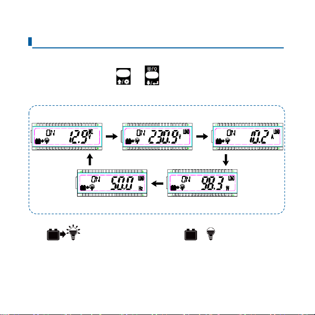
6. Real-time Interface
In the real-time interface(namely, the default interface after the device is
powered on), please click or to display the below parameters in a
cycle.
Note: means, the load being on status, means the load being
off status.
Battery voltage
Load voltage
Load current
Load frequency
Load power

9
7. Setting Interface
The parameter configuration process is as follows.
Step1: In the real-time interface, press for 2s to enter the setting
interface.
Step2: Click or to select the parameter to be configured.
Step3: Press for 2s to enter the configuration interface of the specified
parameter. The parameter value will be flashing.
Step4: click or to select the parameter value.
Step5: Press for 2s to confirm the configuration.
Step6: Click + to exit the current interface.
10
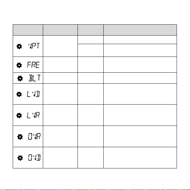
Common parameters are shown in the following table:
LCD
Display
Parameters
Default
User define
Output
voltage class
①
220VAC
220VAC/ 230VAC
110VAc
110VAC/ 120VAC
Output
frequency①
50Hz
50Hz/60Hz
LCD
backlight time
30s
30s/ 60s/100s(ON solid)
Low voltage
disconnect
voltage②
12V: 10.8V
24V: 21.6V
48V: 43.2V
12V:10.5V~14.2V; step size:0.1V
24V: 21V-30.2V; step size:0.1V
48V: 42V-62.4V; step size:0.1V
Low voltage
reconnect
voltage②
12V: 12.5V
24V: 25V
48V: 50V
12V: 11.5V~15.2V; step size:0.1V
24V: 22V-31.2V; step size:0.1V
48V: 43V-63.4V; step size:0.1V
Over voltage
reconnect
voltage②
12V: 14.5V
24V: 29V
48V: 58V
12V: 11.5V~15.2V; step size:0.1V
24V: 22V-31.2V; step size:0.1V
48V: 43V-63.4V; step size:0.1V
Over voltage
disconnect
voltage②
12V: 16V
24V: 32V
48V: 64V
12V: 12.5V~16.2V; step size:0.1V
24V: 23V-32.2V; step size:0.1V
48V: 44V-64.4V; step size:0.1V

11
① After configuring the parameters marked with ①, the inverter will restart
automatically. It will resume work according to the new parameter value.
② NPower and IPower-Plus series support the modification of parameters
marked with ②. Please refer to the following rules for the modification;
otherwise, the parameter setting will not succeed. IPower does not support
modification of parameters marked with ②.
Rules for battery protection voltage:
A.Over voltage limiting voltage(16.2/32.2/64.4V) ≥ Over voltage
disconnect voltage ≥ Over voltage reconnect voltage +1V.
B.Over voltage reconnect voltage ≥ Low voltage reconnect voltage.
C.Low voltage reconnect voltage ≥ Low voltage disconnect voltage +1V.
D.Low voltage disconnect voltage ≥ Low voltage limiting
voltage(10.5/21/42V).

12
Detail status is shown as the following when reaching the protection
voltage point.
Input voltage
protection
Status
Over voltage protection
The output is switched OFF.
The blue indicator fast flashes.
Buzzer beeps.
LCD displays the .
Over voltage reconnect
The blue indicator is ON solid.
The output voltage is normal.
Low voltage protection
The output is switched OFF.
The blue indicator slowly flashes.
Buzzer beeps.
LCD displays the .
Low voltage reconnect
The blue indicator is ON solid.
The output voltage is normal.
Note: Although the inverter is supplied with the over voltage protection
function, the surge voltage is not higher than 20V for the 12V
system, not higher than 40V for the 24V system, and not higher
than 80V for the 48V system; otherwise, the inverter may be
damaged.

13
8. Error Codes
Error
code
Faults
Buzzer
Working
indicator
Fault
indicator
Inverter over
temperature
Heat sink over
temperature
5 beeps
OFF
ON solid
Input over
voltage
5 beeps
Fast
flashing
(1Hz)
OFF
Input low
voltage
5 beeps
Slowly
flashing
(1/4Hz)
OFF
Output short
circuit
5 beeps
OFF
Fast
flashing
(1Hz)
Output
overload
5 beeps
ON solid
Slowly
flashing
(1/4Hz)
Output voltage
abnormal
5 beeps
OFF
OFF

14
9. Specifications
Model
MT91
Compatible products
NPower/IPower-Plus/IPower
Power supply
5VDC
Power supply method
Inverter communication port
LCD visual angle
12' clock
LCD backlight
Yes
Installation method
Surface mounting installation
Self-consumption
14mA/5V(no backlight)
23mA/5V(backlight)
Working temperature
-20℃~+60℃
Storage temperature
-35℃~+70℃
Dimension
φ100mm X 19.4mm(Diameter X Height)
Mounting dimension
φ100mm X 50mm(Diameter X Height)
Mounting hole size
φ3.5mm
Net Weight
65g

15
10. Dimension
Any changes without prior notice! Version number: V1.1

This manual suits for next models
1
Table of contents
Other Epever Measuring Instrument manuals


