EPIC STRENGTH ABDOMINAL GZFI8053.2 User manual
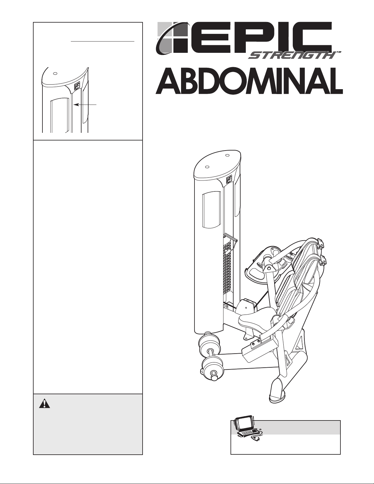
CAUTION
Read all precautions and instruc-
tions in this manual before using
this equipment. Save this manual
for future reference.
OWNER’S MANUAL
Model No. GZFI8053.2
Serial No.
Write the serial number in the
space above for future reference.
QUESTIONS?
At FreeMotion Fitness, we are
committed to providing com-
plete customer satisfaction. If
you have questions, see HOW
TO CONTACT CUSTOMER
CARE on the back cover of this
manual.
Visit our website at
www.freemotionfitness.com
Serial Number
Decal
(inside tower)

2
IMPORTANT PRECAUTIONS . . . . . . . . . . . . . . . . . . . . . . . . . . . . . . . . . . . . . . . . . . . . . . . . . . . . . . . . . . . . . . . . 3
WARNING DECAL PLACEMENT . . . . . . . . . . . . . . . . . . . . . . . . . . . . . . . . . . . . . . . . . . . . . . . . . . . . . . . . . . . . . .4
BEFORE YOU BEGIN . . . . . . . . . . . . . . . . . . . . . . . . . . . . . . . . . . . . . . . . . . . . . . . . . . . . . . . . . . . . . . . . . . . . . . 5
ADJUSTMENTS . . . . . . . . . . . . . . . . . . . . . . . . . . . . . . . . . . . . . . . . . . . . . . . . . . . . . . . . . . . . . . . . . . . . . . . . . . . 6
MAINTENANCE . . . . . . . . . . . . . . . . . . . . . . . . . . . . . . . . . . . . . . . . . . . . . . . . . . . . . . . . . . . . . . . . . . . . . . . . . . .7
CABLE DIAGRAM . . . . . . . . . . . . . . . . . . . . . . . . . . . . . . . . . . . . . . . . . . . . . . . . . . . . . . . . . . . . . . . . . . . . . . . . .11
PART LIST . . . . . . . . . . . . . . . . . . . . . . . . . . . . . . . . . . . . . . . . . . . . . . . . . . . . . . . . . . . . . . . . . . . . . . . . . . . . . .12
EXPLODED DRAWING . . . . . . . . . . . . . . . . . . . . . . . . . . . . . . . . . . . . . . . . . . . . . . . . . . . . . . . . . . . . . . . . . . . .13
HOW TO CONTACT CUSTOMER CARE . . . . . . . . . . . . . . . . . . . . . . . . . . . . . . . . . . . . . . . . . . . . . . .Back Cover
TABLE OF CONTENTS

3
1. Read all instructions in this manual before
using the strength machine. Use the strength
machine only as described in this manual.
2. It is the purchaser’s responsibility to ensure
that there is enough space around the
strength machine for the intended exercise.
Do not crowd the strength machine.
3. Using the anchor strap to provide maximum
stability, anchor the strength machine to the
floor where required or whenever possible.
4. Use the strength machine only on a level sur-
face. Cover the floor beneath the strength
machine to protect the floor.
5. It is the responsibility of the owner to ensure
that all users of the strength machine are
adequately informed of all precautions, have
read and understood all warning and caution
labels, and are informed of how to use the
strength machine properly.
6. Keep children under 12 and pets away from
the strength machine at all times.
7. Always wear athletic shoes for foot protec-
tion while exercising.
8. The strength machine is designed to support
amaximum user weight of 350 lbs. (159 kg).
9. All users of the strength machine should be
instructed to report any injury or strength
machine irregularity to facility staff immedi-
ately.
10. Make sure the weight pin is completely
inserted into one of the weight plates.
11. Check all cables, cable connections, and pul-
leys before each use of the strength machine.
Make sure all parts are properly tightened.
Replace any worn parts immediately.
12. Make sure the cable remains on the pulleys
at all times. If the cable binds while you are
exercising, stop immediately and make sure
the cable is on the pulleys and nothing is
interfering with the cable or pulleys. Replace
all cables at least every two years.
13. Keep hands and feet away from moving
parts. Do not lean on or rest your hands on
the strength machine when it is in use.
14. Keep the strength machine indoors, away
from moisture and dust. Do not put the
strength machine in a garage or covered
patio, or near water.
15. If you feel pain or dizziness at any time while
exercising, stop immediately and begin cool-
ing down.
WARNING: Before beginning this or any exercise program, consult your physician. This
is especially important for persons over the age of 35 or persons with pre-existing health problems.
Read all instructions before using. ICON assumes no responsibility for personal injury or property
damage sustained by or through the use of this product.
WARNING: To reduce the risk of serious injury, read the following important precautions
before using the strength machine.
IMPORTANT PRECAUTIONS
WARNING DECAL PLACEMENT
4
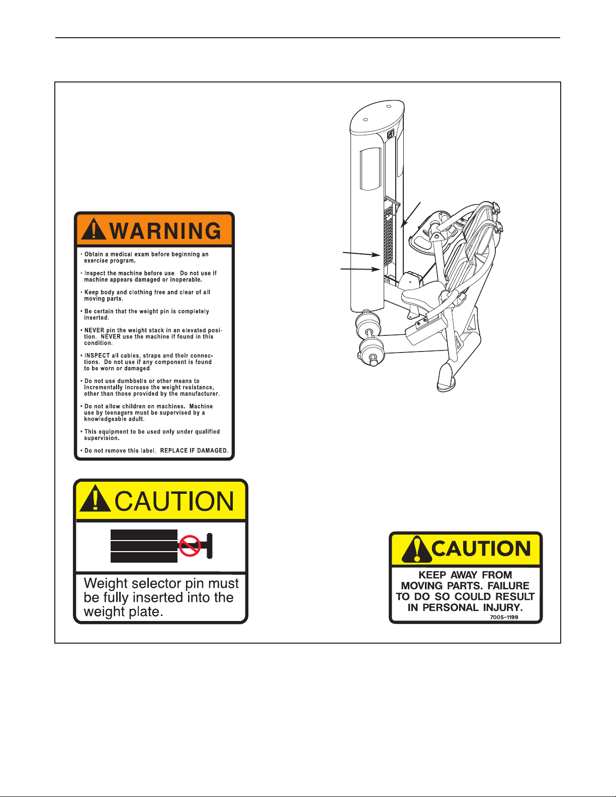
The decals shown below have been placed
on the strength machine in the indicated
locations. If a decal is missing or illegible,
see HOW TO CONTACT CUSTOMER CARE on
the back cover of this manual to order a free
replacement decal. Apply the decal in the
location shown.
Decal 1
Shown at 70%
GZ7003
Decal 3
Shown at 85%
Decal 2
GZ7026
Decal 2
Decal 3
Decal 1
Assembled Dimensions:
Height: 62 in. (1.57 m)
Width: 57 in. (1.45 m)
Depth: 38 in. (0.97 m)
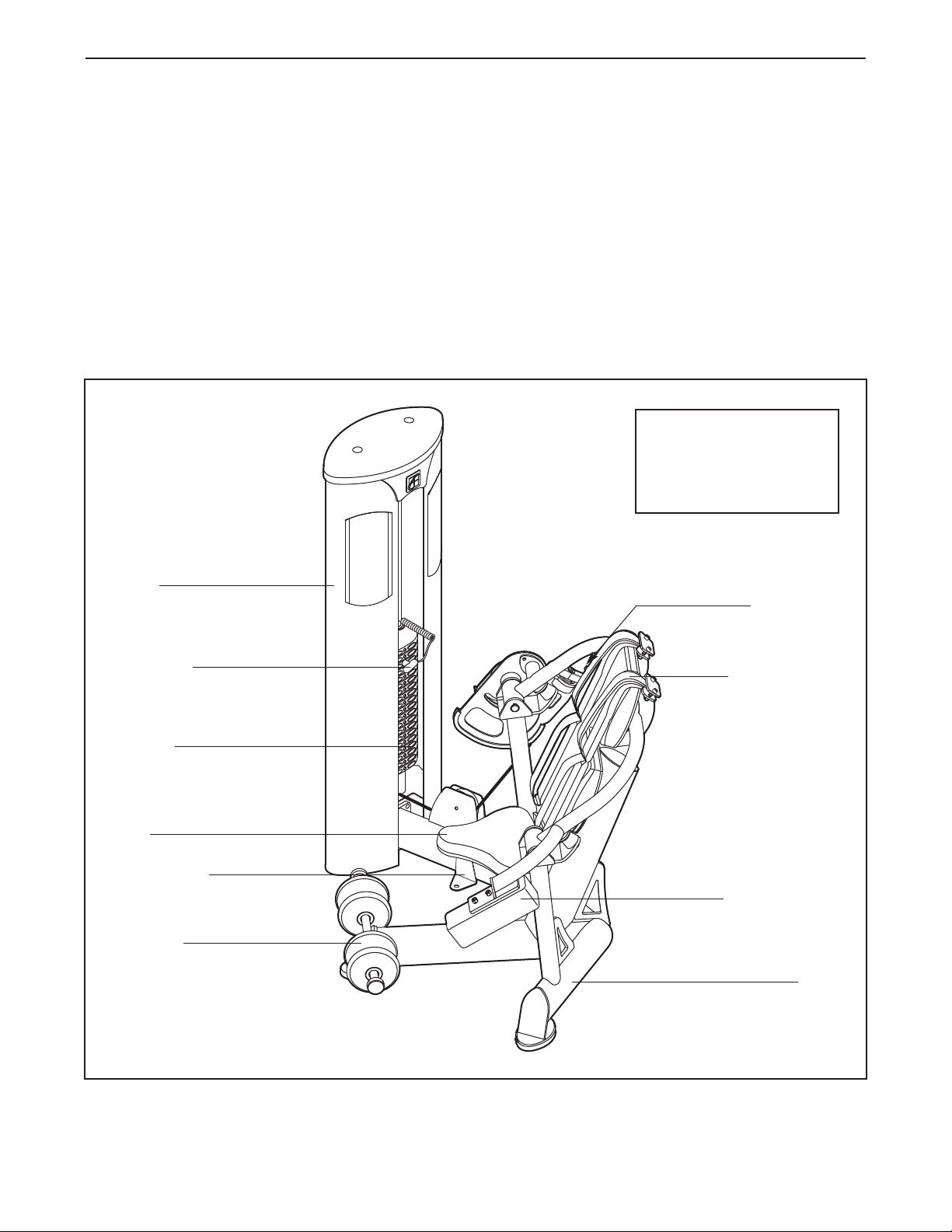
5
Base
Anchor Strap
Weights
Weight Pin
Shin Pad
Counter Weight
Seat
Shoulder Strap
CAM2Knob
Tower
BEFORE YOU BEGIN
Thank you for selecting the EPIC STRENGTH®
ABDOMINAL strength machine. The strength machine’s
stylish ergonomic design and never-before-seen fea-
tures improve upon traditional strength training. The
innovative features and quality construction provide a
reliable product for your club. And the advanced solu-
tions to isolating individual muscle groups make the
ABDOMINAL strength machine a key tool for members
to reach their goals.
For your benefit, read this manual carefully before
using the strength machine. If you have questions
after reading this manual, see HOW TO CONTACT
CUSTOMER CARE on the back cover of this manual.
To help us assist you, please note the product model
number and serial number before calling. The model
number is GZFI8053.2. The serial number can be found
on a decal attached to the strength machine (see the
front cover of this manual).
Before reading further, please review the drawing below
and familiarize yourself with the parts that are labeled.
This section explains how to adjust the strength machine. Make sure all parts are properly tightened each time
the strength machine is used. Replace any worn parts immediately.
6
ADJUSTING THE RESISTANCE
Tochange the amount of resistance for your workout,
insert the weight pin into the desired weight. Make
sure that the weight pin is fully inserted into the
weight.
ADJUSTMENTS
Weight
Weight
Pin
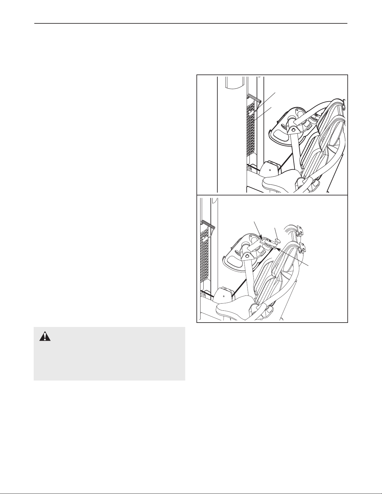
ADJUSTING THE CAM2RESISTANCE
The CAM2resistance can be adjusted to either a 1:1
or a 1:2 ratio to the weight stack. At a 1:1 ratio, the
resistance will be equal to the weight of the weight
stack. At a 1:2 ratio, the resistance will be equal to
one-half the weight of the weight stack.
Tochange the CAM2resistance to a 1:1 ratio, pull the
CAM2knob out and move the CAM2to the HEAVY
slot in the pivot plate. Make sure the knob fully
engages the slot.
To change the CAM2resistance to a 1:2 ratio, pull the
CAM2knob out and move the CAM2to the LIGHT slot
in the pivot plate. Make sure the knob fully engages
the slot.
CAM2
Knob
HEAVY
Slot
LIGHT
Slot
WARNING: Always make sure that
the CAM2knob is fully engaged into the slot in
the pivot plate before using the strength
machine. Make sure the spring (not shown) is
in place and functioning properly.

7
MAINTENANCE
For safe and trouble-free operation of your EPIC STRENGTH strength equipment, it is important to perform
preventive maintenance on a regular basis. Make sure that all parts are properly tightened each time the strength
machine is used. Replace any worn parts immediately. The strength machine can be cleaned with a cloth damp-
ened with water and a mild, non-abrasive soap. Do not use solvents.
Note: Instruct all personnel to perform equipment inspection and maintenance requirements. Personnel must
record and report any accident. For any questions or concerns, see HOW TO CONTACT CUSTOMER CARE
on the back cover of this manual.
Use only original EPIC STRENGTH parts for repair or replacement to maintain your machine’s warranty.
FreeMotion Fitness recommends the following procedures:
SCHEDULED MAINTENANCE
DAILY
1. Upholstery—General cleaning:
•Wipe using a cloth dampened with a solution of
warm water and a mild soap.
•If necessary,use a soft bristle brush with the
cleaning solution.
•Always remove the cleaning solution using a
cloth dampened with clean water. Rinse often.
2. Upholstery—Difficult stains:
•Spray the stain with a non-abrasive household
cleaner such as FORMULA 409®cleaner,
SIMPLE GREEN®,or a similar product.
•Rub the area gently and let it sit for a few min-
utes.
•Rinse thoroughly using a cloth dampened with
clean water.
•Repeat if necessary using a soft bristle brush.
Optional method for difficult stains:
•Rub the area gently using a cloth dampened
with rubbing alcohol.
•Rinse thoroughly using a cloth dampened with
clean water to remove alcohol residue.
CAUTION: When using any cleaning product, try
it first in an inconspicuous place to ensure there
is no damage to the material. Follow the direc-
tions and adhere to the safety precautions of the
manufacturer of each cleaning agent used.
FreeMotion Fitness and its vendors cannot be
held liable for damage or injuries resulting from
the use or misuse of cleaning products.
3. Towers and Frames:
•Wipe using a cloth dampened with a solution of
warm water and a mild soap.
•Rinse and dry thoroughly.
Important: Do not use abrasive cleaners because
they may scratch the equipment. Strong cleansers
and abrasives will damage decals. Use caution
around decals. Do not use solvents such as lacquer
thinner, kerosene, gasoline, or similar liquids.
WEEKLY
1. Hardware:
•Check all nuts and bolts. Tighten them as
required.
2. Cables:
•Check all cables for proper tension.
•Check the entire length of the cable by pulling
each handle individually to its fully extended
position and inspecting the cable that is
exposed on the exterior of the machine, as well
as the cable inside of the cut stack tower.
•Run your fingers along the cable, paying close
attention at the bends and attachment points.
•Watch for the following conditions, which may
indicate a worn cable in need of replacement:
A. torn or split cable sheath that exposes the
cable
B. kinked or severely bent cable
C.curled or twisted sheath
D.stretched cable sheath, showing a thinning
cross-section
A
B
D
C

8
MONTHLY
1. Grips:
•Check and replace as needed.
YEARLY OR AS REQUIRED
1. Weight Stack Guide Rods:
•Clean and lubricate the full length by wiping
using a soft cloth containing a light weight
motor oil, 10W-40 or 10W-30 weight. Only a
light coating over the entire length is needed.
Note: Do not use TEFLON®or silicone-based
lubricants.
CUSHION ATTACHMENT
Important: All EPIC STRENGTH cushions are fabri-
cated using dense plywood with tee-nuts installed for
bolting to the machine framework. Because these tee-
nuts are held by the plywood, they will not withstand
the torque that standard nuts and bolts will.
Therefore, when tightening the cushion bolts, turn
them only until they are snug and the cushion does
not move or feel loose. Overtightening may strip the
tee-nuts from the plywood and make it impossible to
remove the cushion in the future.
CABLE TENSION CHECK
1. Insert the weight pin into the top weight plate.
2. Slowly raise and lower the top weight by normal
machine use. The top weight should come to
rest just on top of the second weight when the
handle is returned to the resting position.
•If there is too much tension on the cable, the
top weight will not rest on the second weight,
and it may be difficult to insert the weight pin
into the weight plates.
•If there is not enough tension on the cable, the
top weight will not be lifted immediately when
one of the handles is pulled. Ideally, the han-
dle/cable should not move more than 1/2"
(1.3cm) from the resting position before the top
weight begins to be lifted.
3. If there is too much or not enough tension on the
cable, adjust the cable as described in CABLE
ADJUSTMENTS on page 9.
CABLE GUARDS
Check for alignment periodically to ensure that cable
guards are not rubbing on the cable and that they are
performing their intended duty. If the alignment is not
proper, loosen the bolt slightly, readjust the cable
guard as necessary, and retighten the bolt.
Correct Alignment
Incorrect Alignment
Rubbing Rubbing
Out of
Alignment
Guards Guards
Cable
Cable
Pulley
9
CABLE ADJUSTMENTS
CAUTION: After making any cable adjustment, pull
the handle using a light load and have someone make
sure that the cable is not derailed from a pulley or rub-
bing on a guard (see CABLE GUARDS on page 8).
INITIAL ADJUSTMENT
Top Weight Adjustment—
Tools required: Hammer, 1/8” punch, 3/16” roll pin
1. Lift the coupler cover from the top weight coupler.
2. Remove the roll pin from the top weight coupler
with an 1/8” punch and a hammer.
3. Align the hole in the cable coupling with the
appropriate adjustment hole in the top weight
coupler:
•If more slack is needed in the cable, align the
cable coupling with a higher hole.
• If less slack is needed in the cable, align the
cable coupling with a lower hole.
4. With the cable coupling aligned with the new
hole, drive a new roll pin into the top weight cou-
pler and cable coupler.
5. Lower the coupler cover over the top weight
coupler.
Adjustment Hole
Cable Coupling
Top Weight
Coupler
Coupler Cover
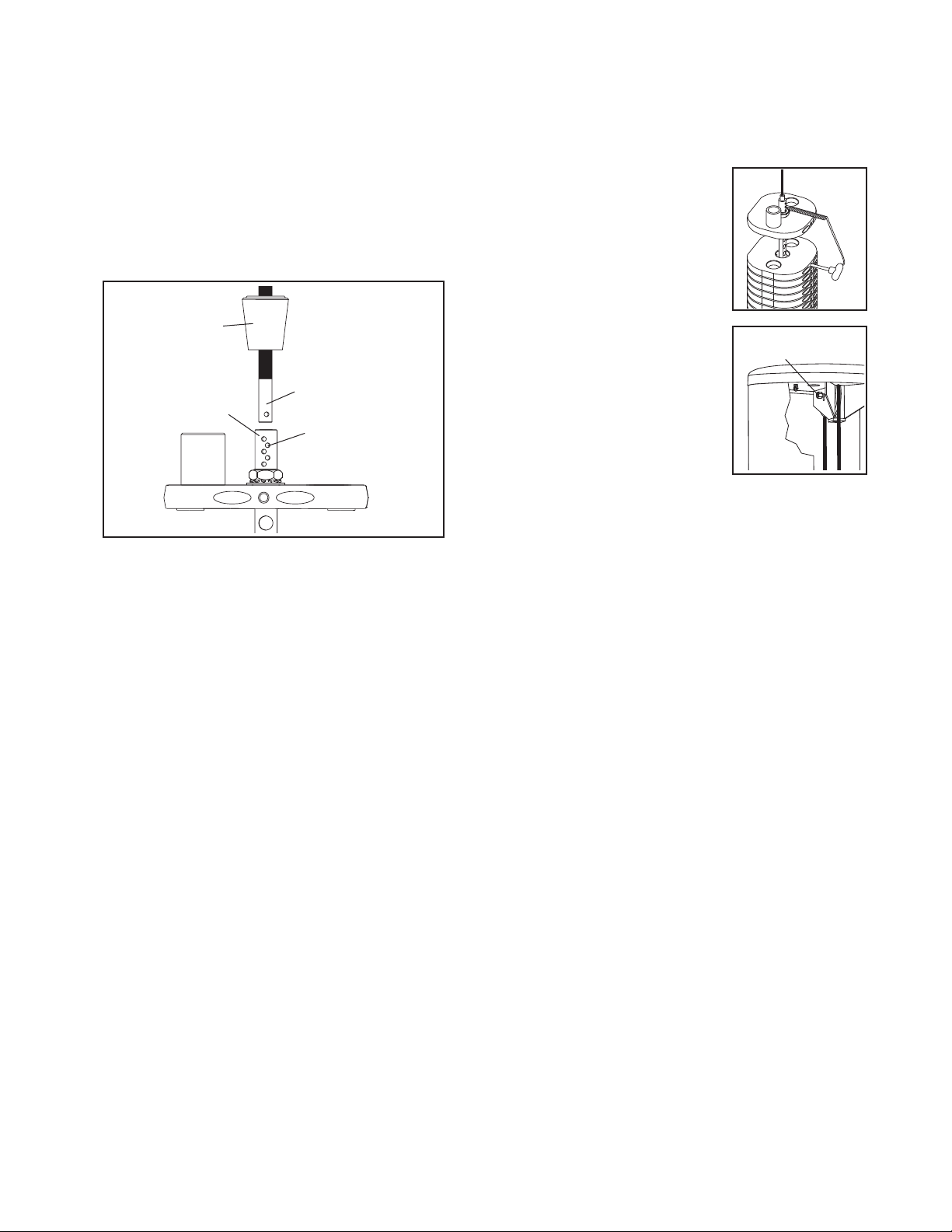
ADDITIONAL ADJUSTMENT
Tower Pulley Adjustment–
Tools required: 5/16" Allen wrench/hex key, 9/16"
open end wrench/spanner
1. Lift the top weight off the
weight stack and insert the
weight pin into the second
weight and the sixth hole
from the top of the weight
rod.
2. Loosen the locknut attach-
ing the pulley to the brack-
et in the top of the tower.
3. Move the pulley to the appropriate location in the
bracket:
•If more slack is needed in the cable, move the
pulley down.
• If less slack is needed in the cable, move the
pulley up.
4. Make sure that the cable guard is properly ori-
ented (see CABLE GUARDS on page 8) and
retighten the locknut attaching the pulley to the
bracket.
5. Lift the top weight and remove the weight pin.
Lower the top weight onto the second weight.
6. Readjust as necessary.
Locknut

10
SERVICING THE WEIGHT STACK
For required parts, see HOW TO CONTACT CUS-
TOMER CARE on the back cover of this manual.
1. Remove the wingnuts under the tower cap and
remove the tower cap from the tower.
2. Remove the screw from the top of each guide
rod.
3. Lift the coupler cover and drive the roll pin from
the top weight coupler with an 1/8” punch and a
hammer—this will release the cable.
4. Lift the guide rods out of the top of the tower.
5. Lift and rotate the top weight and weight pin, and
remove them through the front opening of the
tower.
6. Servicing the weight stack involves replacing the
two guide bushings and the weight insert in the
top weight. First, use a punch to drive the two
existing guide bushings and weight insert out of
the top weight.
7. To insert the new guide bushings and weight
insert, hold a bushing square to the face of one
of the holes in the top weight, place a protective
piece of wood on top of the bushing, and lightly
tap the bushing into place. The bushing should
be flush with the surface. Repeat with the other
guide bushing and weight insert.
8. Replace the top weight and weight pin on top of
the weight stack.
9. Reattach the cable to the top weight coupler.
10. Clean and lubricate the guide rods by wiping
them with a soft cloth containing a lightweight
motor oil, 10W-40 or 10W-30 weight. Apply only a
light coating over the entire length. Note: Do not
use TEFLON®or silicone-based lubricants.
11. Reinsert the guide rods through the top of the
tower and into the weight stack.
Note: If the weight stack has shifted, use a
short bar to realign the holes in the weight
plates. Hold the weight plates while inserting
the guide rods.
12. Reattach the guide rods to the top of the frame
with the two screws.
13. Insert the weight pin into the top weight. Pull the
handle, lifting the top weight all of the way to the
top of the guide rods. Slowly return the handle to
the resting position. If the top weight sticks,
loosen one of the guide rod screws. Lift the top
weight to the top again. Retighten the guide rod
screw. Check the full travel again and readjust
the guide rods as necessary.
14. While slowly pulling the handle, have someone
check the cable guard on the top weight to
ensure that it is not dragging or rubbing on the
cable.
15. Replace the tower cap and retighten the
wingnuts onto the bolts.
Weight
Insert
Guide
Bushings
Top Weight
Top Weight
Coupler
WARNING: Do not force the
guide rods into the weights; doing so will
damage the guide bushings and the weight
inserts.
11
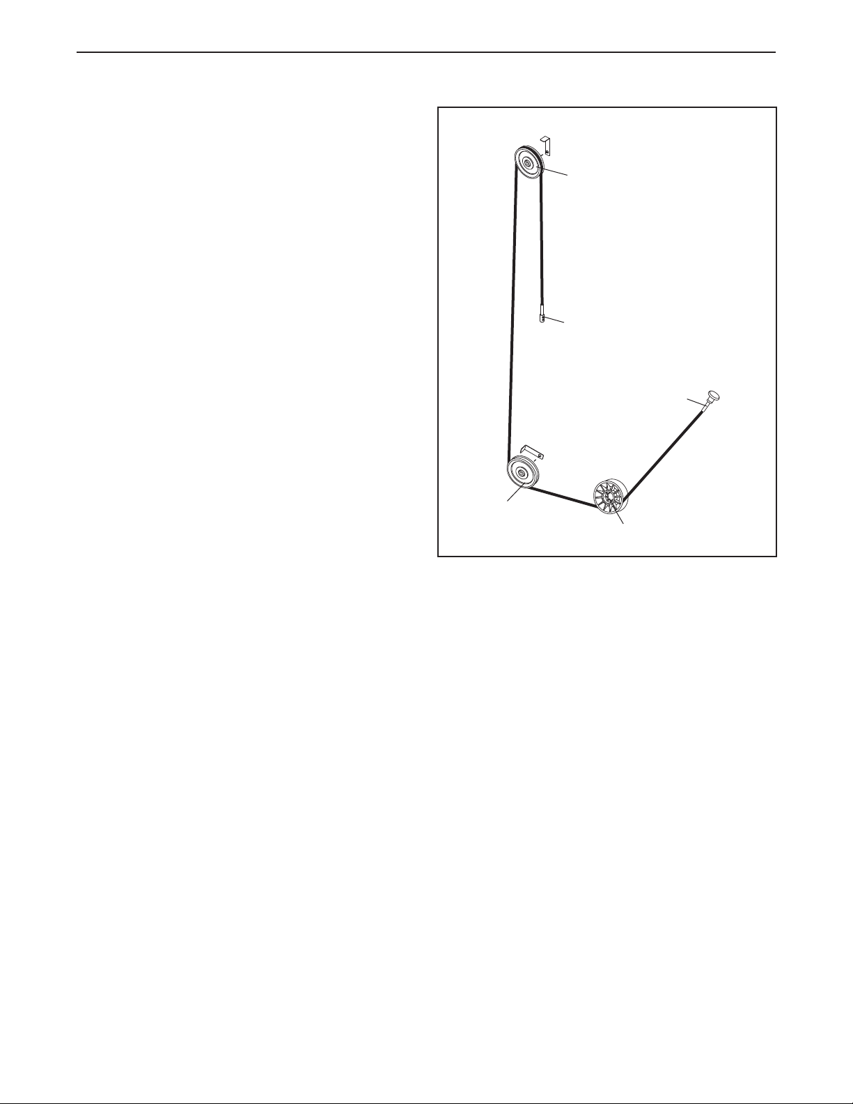
CABLE DIAGRAM
The cable diagram below shows the proper route of
the cable. Use the diagram to make sure that the
cable and the cable guards have been assembled
correctly. If the cable has not been correctly routed,
the strength machine will not function properly and
damage may occur. The numbers show the correct
route of the cable. Make sure that the cable guards
do not touch or bind the cable.
4
1
2
3
5

12
Key No. Qty. Description Key No. Qty. Description
1 1 Base
2 1 Tower
3 1 Tower Cap
4 1 Long Panel Frame
5 1 Long Panel
6 1 Short Panel Frame
7 1 Short Panel
8 1 Rear Plate Frame
9 1 Rear Name Plate
10 1 Pivot Frame
11 1 Counter Weight
12 2 Backrest
13 2 Weight Guide
14 2 Long Trim
15 1 Short Trim
16 2 Shoulder Strap
17 1 Cam
18 19 Weight
19 1 Top Weight
20 1 Weight Rod
21 1 3/8" Fine Thread Nut
22 1 Seat
23 1 Seat Frame
24 2 Shin Pad
25 2 Round Outer Cap
26 2 Shin Pad Sleeve
27 4 Sleeve Bushing
28 1 Shin Bar
29 1 Anchor Strap
30 3 Base Foot
31 2 Large Bumper
32 1 Pivot Rod
33 1Short Pivot Rod
34 2 Spacer
35 2 Small Weight Bumper
36 3Rod Washer
37 39 Weight Insert
38 2 Guide Bushing
39 13/16" Roll Pin
40 1 Weight Pin
41 1 Star Washer
42 1 Rod Nut
43 1Coupler Cover
44 2 3/8" x 3/4" Self-tapping Bolt
45 1 3/8" x 3/4" Button Bolt
46 2 3/8" x 4 1/2" Bolt
47 1 Bungee
48 2 Bungee Tie
49 2 3/8" x 1" Button Bolt
50 1 Cable
51 2 Pulley
52 2 Cable Guard
53 1 Cover
54 1 Insignia
55 1 “V”-pulley
56 4 Tower Foot
57 1 Cable Switch Lever
58 1 CAM2Knob
59 2 Flange Bushing
60 2 Strap Plate
61 6 1" Bearing
62 5 1" Nylon Washer
63 4 Snap Ring
64 2 “V”-pulley Bearing
65 2 Pivot Bushing
66 2 Collar Clamp
67 1 5/16" Washer
68 2 Wingnut
69 14 3/8" x 1/2" Button Bolt
70 6 3/8" x 1" Non-patch Bolt
71 2 1/4" x 1" Button Bolt
72 2 3/8" x 1" Bolt
73 6 3/8" x 1 1/4" Bolt
74 2 3/8" x 6 1/2" Non-patch Bolt
75 2 1/2" x 1 1/4” Bolt
76 23/8" x 2" Bolt
77 13 3/8" Nylon Locknut
78 1 3/8" x 2 1/2" Bolt
79 2#4 x 5/8" Screw
80 2 #4 Nut
81 4 Rivet
82 1Cable Switch Terminal
83 5 3/8" Serrated Washer
84 2 Pivot Bushing
85 1 Spring
#1User’s Manual
PART LIST—Model No. GZFI8053.2 R0405A
If replacement parts are needed, or if parts are missing or damaged, see HOW TO CONTACT CUSTOMER
CARE on the back cover of this manual.
Note: “#” indicates a non-illustrated part. Specifications are subject to change without notice.

EXPLODED DRAWING—Model No. GZFI8053.2 R0405A
73
30
1
51
52
77
76
8
9
7171
3
68
4
5
2
6
7
53 54
51
52 76
77
56
69
56
56
69
25
66
27
26
24
26
27
66
25
29
22
23
70
41
50
43
42
36
38 37
19
39
38
20
37
37
18
35
34
36 36
35
27 28
72
69
30 30
69
75
78 65 64
55
64
65
77
17 61
31
61
63
62
14 14
13
44
12
12
74
70
73
73
60
60
77
10
61
62
32
61
62
63
61
62
49
61
62
63
61
62
63
46
11
77
82
77
58
73
31
16
15
16
69
33
77 40
77
47
48
79
80
81
81
81
81
59
59
57
67 45
83
83
84
84
83
83
69
24
50
21
83
85
13

Part No. GZ7251 R0405A Printed in USA © 2005 ICON IP, Inc.
HOW TO CONTACT CUSTOMER CARE
If you have questions after reading this manual, or if you require assistance, please contact Customer Care at
the address and phone number listed below. Please be prepared to give the following information:
•The MODEL NUMBER of the product (GZFI8053.2).
• The NAME of the product (EPIC STRENGTH ABDOMINAL strength machine).
• The SERIAL NUMBER of the product (see the front cover of this manual).
• When ordering replacement parts, please also give the KEY NUMBER and DESCRIPTION of the part(s) (see
the PART LIST and the EXPLODED DRAWING on pages 12 and 13 of this manual).
Customer Care: 1-800-201-2109, Monday–Friday, 8 a.m.–5 p.m. Mountain Time
FreeMotion Fitness, Inc. • 1096 Elkton Dr., Suite 600 • Colorado Springs, CO 80907
Table of contents
Other EPIC STRENGTH Fitness Equipment manuals

EPIC STRENGTH
EPIC STRENGTH BARBELL RACK User manual

EPIC STRENGTH
EPIC STRENGTH Dip Chin Ab User manual

EPIC STRENGTH
EPIC STRENGTH GZFW20812 User manual

EPIC STRENGTH
EPIC STRENGTH GZFI8063.2 User manual

EPIC STRENGTH
EPIC STRENGTH GZFW21210 User manual

EPIC STRENGTH
EPIC STRENGTH SHOULDER GZFI8073.2 User manual
Popular Fitness Equipment manuals by other brands


CYBEX
CYBEX 13250-999-4 AC owner's manual

MOODLight
MOODLight SM9126 manual

ParaBody
ParaBody Parabody 844 Lat Option user guide

Body Sculpture
Body Sculpture BE-1675-H manual

Sunny Health & Fitness
Sunny Health & Fitness SF-E3981 user manual

Nautilus
Nautilus NP-L8500 Owner's manual and installation instructions