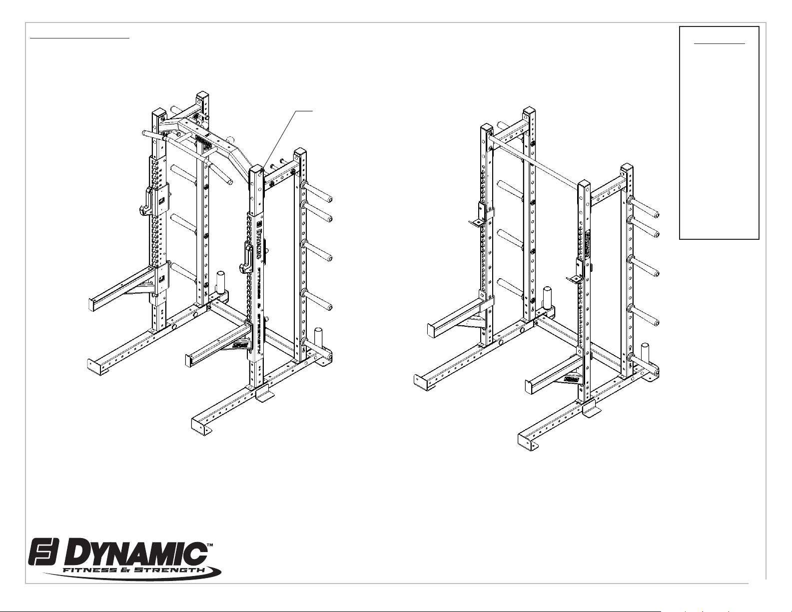
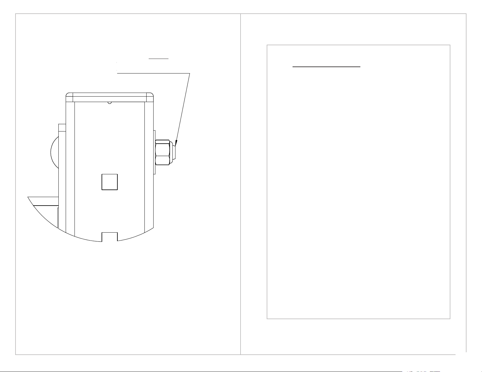
All parts have a part number.
Position the part number to be
covered by its mating component
or up as shown in this view.
74.57
63.48
SCALE 1 : 10
A
DETAIL
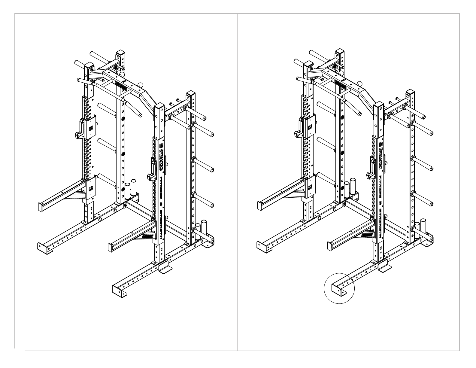
The mounting access for bar
catch and safety must be to inside
of rack as shown.
Note: Titan G2 Series will not have an
upright wrap as shown
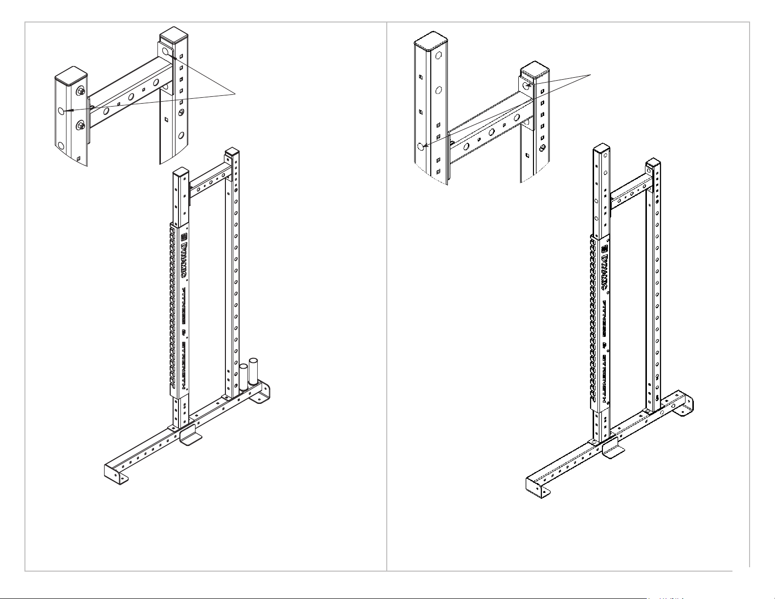
Step one
Attach bar holders to ends of each base as shown.
Depending on the build of your rack the bar holder
number may vary. (Max two per side)
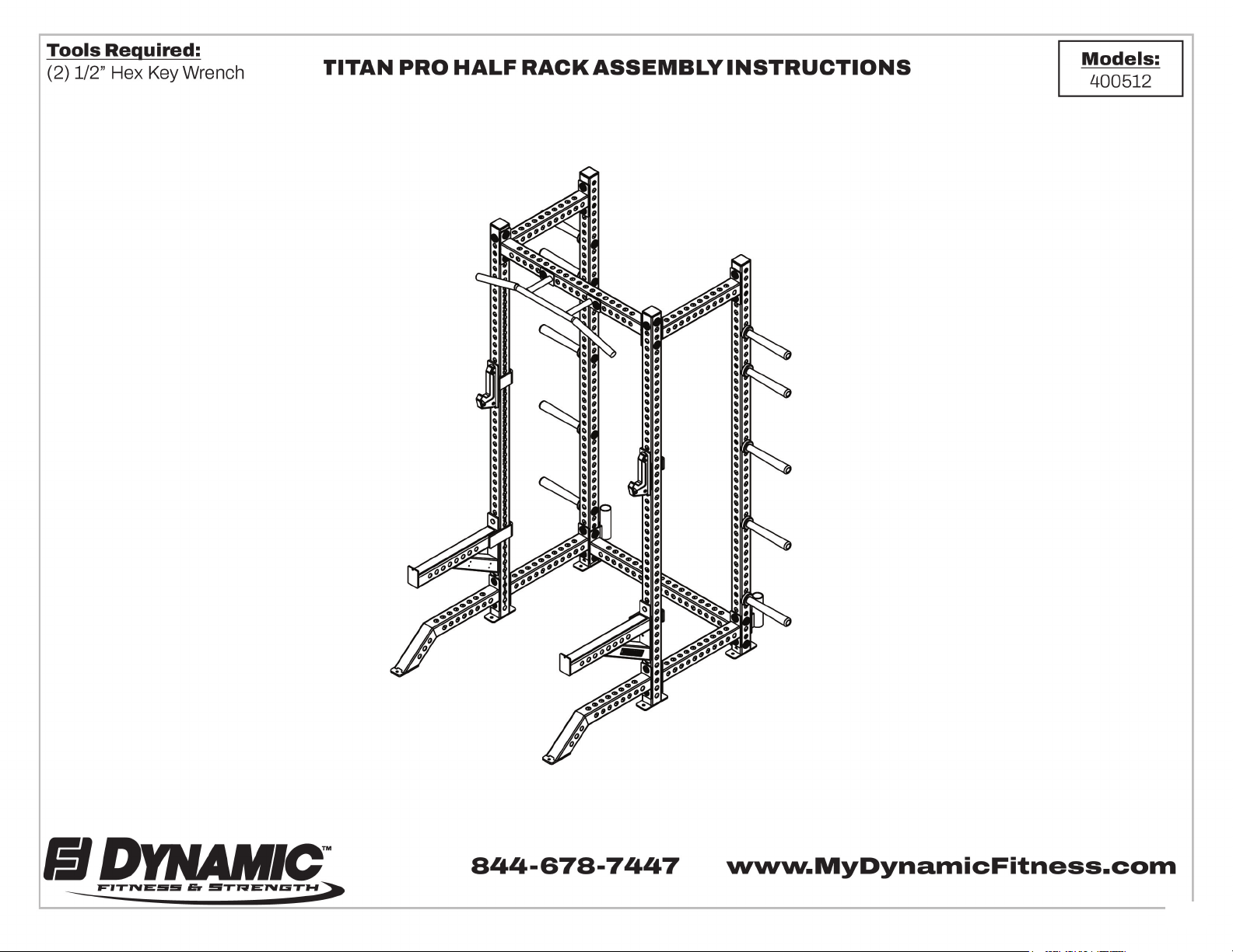
Before Assembling this rack:
Consider how much space will be
required around the unit to access weights
and not interfere with other equipment.
Step Two
Attach storage post and front upright to right
base as shown. Repeat for left side.
Note: The base mounting flanges must face outward
A
All parts have a part number.
Position the part number to be
covered by its mating component
or up as shown in this view.
74.57
63.48
SCALE 1 : 10
A
DETAIL
The mounting access for bar
catch and safety must be to inside
of rack as shown.
Note: Titan G2 Series will not have an
upright wrap as shown
Step one
Attach bar holders to ends of each base as shown.
Depending on the build of your rack the bar holder
number may vary. (Max two per side)
Before Assembling this rack:
Consider how much space will be
required around the unit to access weights
and not interfere with other equipment.
Step Two
Attach storage post and front upright to right
base as shown. Repeat for left side.
Note: The base mounting flanges must face outward
A
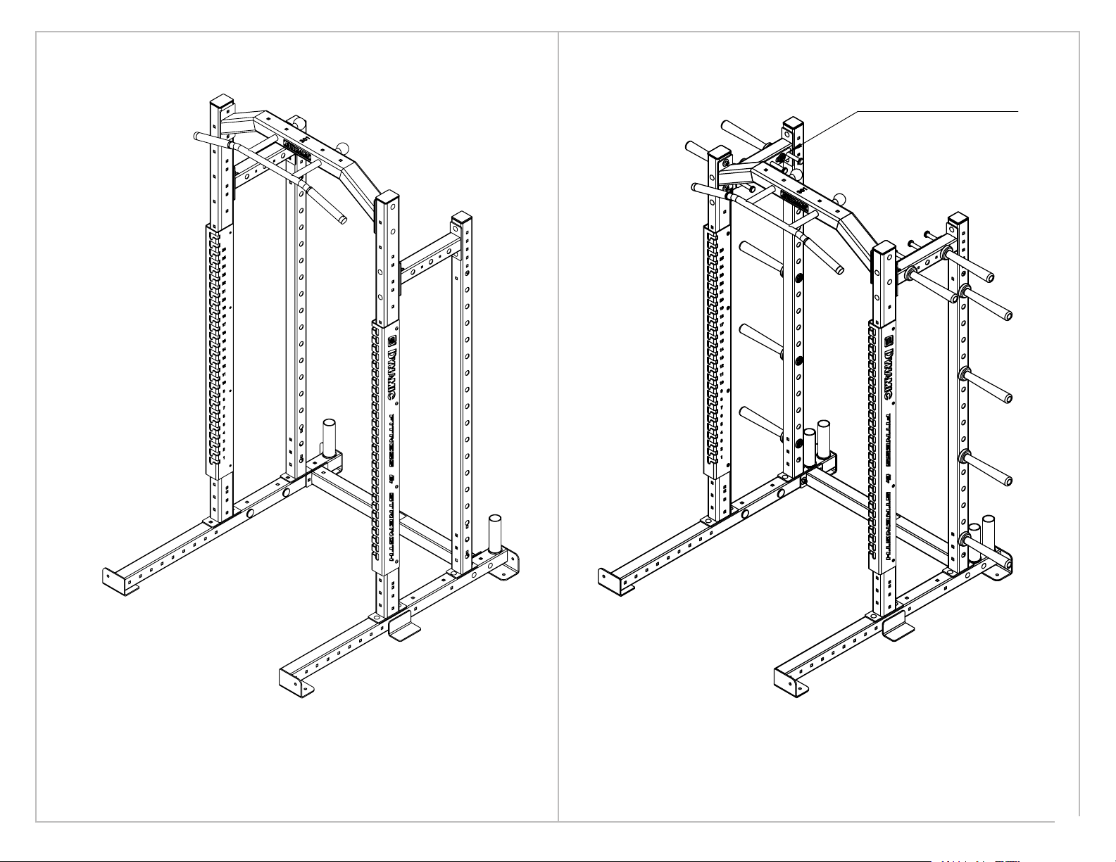
All parts have a part number.
Position the part number
to be covered by its mating
component or up as shown
in this view.
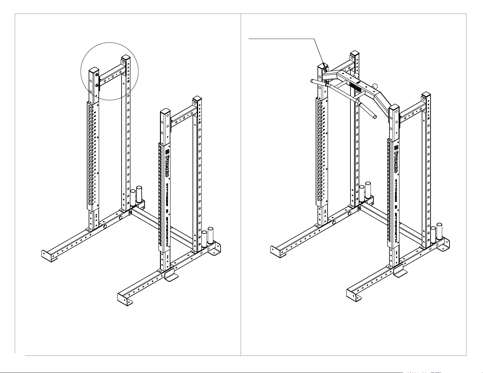
Before assembling this rack:
Consider how much space will be
required around the unit to access weights
and not interfere with other equipment.
The mounting access for bar
catch and safety must be to inside
of rack as shown.
Note: Titan G2 Series will not have an
upright wrap as shown
Step 2
Attach storage post and front upright to right
base as shown. Repeat for left side.
Note: The base mounting anges must face outward
Step 1
Attach bar holders to ends of each base as shown.
Depending on the build of your rack the bar holder
number may vary. (Max two per side)
6