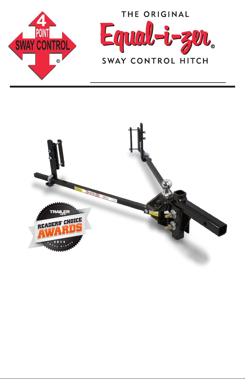
Equalizer 90-00-0400 User manual

OWNER’S MANUAL
90-00-0400 400 lb. max loaded tongue / 4,000 lb. max loaded trailer weight
MADE IN THE
U.S.A.
EqualizerHitch.com
DEALERS: PLEASE PASS THIS MANUAL ON TO THE
END USER AFTER HITCH INSTALLATION
Hitch Ball
Not Included
The Best Protection For Your Journey™
A
W
A
R
D
W
I
N
N
E
R
2014
3-time Trailer Life Magazine
Reader’s Choice Gold Winner
READ ENTIRE MANUAL BEFORE STARTING INSTALLATION

2EqualizerHitch.com
Table of Contents
Page
Parts Breakdown . . . . . . . . . . . . . . . . . . . . . . . . . .4
Operator Safety . . . . . . . . . . . . . . . . . . . . . . . . . . . 6
About Your Hitch. . . . . . . . . . . . . . . . . . . . . . . . . . 7
Step 1: Position Tow Vehicle and Trailer. . . . . . . . . . . . . . 8
Step 2: Install the Hitch Ball . . . . . . . . . . . . . . . . . . . .9
Step 3: Attach Hitch Head to Shank . . . . . . . . . . . . . . . 10
Step 4: Sway Bracket Assembly . . . . . . . . . . . . . . . . . 12
Step 5: Spring Arm Setup . . . . . . . . . . . . . . . . . . . . 15
Step 6: Weight Distribution Setup . . . . . . . . . . . . . . . . 16
Step 7: Weight Distribution Adjustments. . . . . . . . . . . . . 19
Step 8: Trailer Pitch Adjustment . . . . . . . . . . . . . . . . . 21
Step 9: Final Tightening . . . . . . . . . . . . . . . . . . . . . 22
Step 10: Regular Maintenance . . . . . . . . . . . . . . . . . . 23
Service Tech Checklist . . . . . . . . . . . . . . . . . . . . . . 25
Appendix A: Troubleshooting Guide. . . . . . . . . . . . . . . 26
Appendix B: Weight Distribution Adjustments . . . . . . . . . 28
Warranty . . . . . . . . . . . . . . . . . . . . . . . . . . . . . 29
TOOLS NEEDED FOR INSTALLATION
The following tools will help you to install the hitch properly:
15/16” box-end wrench (shank bolts)
15/16” socket wrench (shank bolts)
9/16” box-end wrench (link plates)
9/16” socket wrench (link plates)
5/8” socket wrench (angle set bolt and L-bracket)
(2) 7/16” socket or box-end wrenches (snap-up lever)
Adjustable wrench
Measuring tape
Pencil
Torque wrench capable of 180 ft-lbs of torque. (shank bolts)
Recommended tools for installing the hitch ball:
1-7/8” Thin walled socket and 4” extension
Torque wrench capable of 430 ft-lbs of torque (or higher if hitch
ballmanufacturerspecies).

3
A product of
Congratulations on your purchase of The Original
Equal-i-zer®Sway Control Hitch.
Thank You for your purchase and welcome to
the Equal-i-zer hitch family. We appreciate your busi-
ness and constantly strive to exceed your expecta-
tions.
Read this owner’s manual thoroughly to become fa-
miliar with proper setup and maintenance procedures
to ensure that your Equal-i-zer hitch will give you
maximum performance and years of service.
Happy Towing,
The Employees of Progress Mfg. Inc.
HITCH OWNER: A REPLACEMENT COPY OF THIS
MANUAL MAY BE DOWNLOADED FROM
EQUALIZERHITCH.COM OR BY CALLING
1-800-478-5578.
PLEASE KEEP THIS MANUAL AS A REFERENCE FOR
ADJUSTMENT AND MAINTENANCE.

4EqualizerHitch.com
123
18
19
23
24
25
27
20
26
28
30
29
22
21
4
6
7
8
9
10
11
12
13
5
20 14
15
16
17
Item # 29 - Socket Warning Sticker
Parts Breakdown

5
A product of
Item # Part Number Part Descripon Qty.
1 90-02-4140 Adjustable Shank 1
2 90-04-9224 Hitch Pin Clip 1
3 90-03-9220 Hitch Pin 1
4 90-03-9475 3/8” Nut 4
5 90-03-9490 3/8” Lock Washer 4
6 90-02-5240 Inside Link Plate 2
7 90-03-9480 7/16” x 1-1/4” Bolt 4
8 90-02-5340 Outside Link Plate 2
9 90-03-9470 3/8” x 3-1/4” Bolt 4
10 90-02-5140 L-Bracket 2
11 90-03-9486 7/16” Nylock Nut 4
12 90-03-9460 L-Pin 2
13 90-04-9208 L-Pin Clip 2
14 90-03-6200 Snap-up Handle 1
15 90-04-9240 1/4” Snap-up Bolt 1
16 90-03-6140 Snap-up Hook 1
17 90-04-9244 1/4” Snap-up Nut 1
Item # Part Number Part Descripon Qty.
18 90-03-9425 5/8” Nut 2
19 90-03-9420 5/8” Lock Washer 2
20 90-03-9415 5/8” Washer 4
21 90-03-9105 Spacer Rivet 1
22 90-04-9110 Spacer Washer 6
23 90-03-9212 Socket Pin 2
24 90-04-9216 Socket Pin Clip 2
25 90-03-9700 Angle Set Bolt 1
26 90-02-0400 400 / 4,000 lb. head 1
27 90-03-9410 5/8” x 4-1/2” Bolt 2
28 BD043 Arm Warning Stickers
4,000 lb. arm sticker 2
29 BD035 Socket Warning Sticker 2
30* 90-02-0499 4,000 lb. Spring Arm 2
* Each package contains two (2) spring arms. These arms are spe-
cicallysizedforyourhitchhead.Springarmswillnotfunction
with a hitch head of a different rating.
www.equalizerhitch.com
4-POINT
SWAY CONTROL
™
ATTENTION
IT IS THE OPERATORS RESPONSIBILITY TO READ AND
UNDERS
TAND PRODUCT INSTRUCTIONS AND PROPER USE.
IT IS
THE DRIVER’S RESPONSIBILIT
Y TO MAKE THE NECESSARY
ADJUSTMENTS
TO THEIR DRIVING HABITS, TRAILER, TOW VEHICLE,
AND T
OWING EQUIPMEN
T TO AVOID TRAILER SWAY. TRAILER
SWAY HAS MANY
CAUSES, INCLUDING: IMPROPER
TRAILER LOADING,
TIRE PRESSURE, DRIVING
TECHNIQUES, SPEED, PASSING VEHICLES,
WEA
THER CONDITIONS, ROAD CONDITIONS,
AND OTHERS. THERE
IS NO 100% QUALI
TATIVE MEASUREMENT OF TRAILER SWAY OR
SWAY
CONTROL. USERS MUS
T EXERCISE CAUTION AT ALL TIMES
WHILE TOWING A TRAILER AND ABIDE BY ALL TRAFFIC LAWS.
Model# 90-00-XXXX
Max. Tongue Weight ___ Lbs.
Max. Trailer Weight _____ Lbs.
V5 & SAE Tested
Equal-i-zer®is a product of Progress Mfg. Inc.
For a copy of the hitch instructions call
Progress Mfg. Inc. at 1-800-478-5578 or visit:
MADE IN THE USA
EQAS0308
Item# 28 - Spring Arm Warning Sticker

6EqualizerHitch.com
Operator Safety
WARNING
WARNING
Read and understand all safety warnings, setup, use, and maintenance
instructions of your trailer, tow vehicle, and hitching equipment before
installing your hitch or towing your trailer. Failure to follow these
instructions may result in severe injury or death.
Never cut, weld, grind, bend, or modify hitch components in any way.
It is the driver’s responsibility to adjust equipment and driving habits
to match towing conditions. The driver is responsible for their own
safety and the safety of passengers.
Never exceed the specied weight ratings for the trailer, tow vehicle,
hitch, hitch ball, or any other towing equipment.
No hitch setup guarantees that trailer sway will be altogether avoided.
Always load trailer correctly. Follow trailer and tow vehicle
manufacturers’ recommendations for placement and quantity of cargo.
Towing with a tongue weight more than 15% or less than 10% of gross
trailer weight greatly increases the likelihood for loss of vehicle control.
Always use a hitch ball with a rating that equals or exceeds the trailer
Gross Vehicle Weight (GVW). Always use a hitch ball size that
correctly matches your trailer coupler size and make sure it is coupled
securely before towing.
Measuring weight distribution setup well does not ensure safe towing.
The operator is responsible for making necessary adjustments to the
hitch to optimize weight distribution and sway control. Each trip is
different, and the weight distribution setup and towing performance
should be evaluated by the operator and adjusted when necessary.
Never tow with your hitch adjusted incorrectly.
Check all hardware before each trip. Do not tow your trailer until all
bolts and nuts have been checked for wear and fatigue, are properly
tightened, and all pins and clips are securely in place.
Do not tow with your hitch engaged on rough roads, through profound
ditches, dips and swales, or while launching a boat. Excessive strain on
the spring arms and hitch head may cause hitch fatigue or failure.

7
A product of
If your dealer installed your hitch, make sure to verify that it is still
adjusted correctly after loading your trailer and tow vehicle for your
trip.
Replace worn, faded, or unreadable warning stickers on the spring
arms.
Do not transfer hitch to a different tow vehicle or trailer without
re‑adjusting the hitch for proper weight distribution.
CAUTION
CAUTION
Do not loosen or remove any part of the hitch except the L‑pins and
L‑pin clips while the hitch is under load.
Always secure tow vehicle and trailer with parking brake and wheel
chocks before setting up or adjusting hitch.
Disengage weight distribution before towing or backing the trailer
where there is a signicant transition in grade which puts excessive
strain on the hitch, e.g. backing from a at street to a steep uphill
driveway.
About Your Hitch
Weight Distribution:
Weight distribution is the ability of a hitch to transfer some of the tongue
weight of the trailer from the rear axle of the tow vehicle to the front axle of
the tow vehicle, and backward to the trailer axles. Without weight distribu-
tion the tow vehicle “teeter-totters” on the rear axle of the tow vehicle, and
unweights the front axle. Proper weight distribution transfers weight back
to the front steering axle, forcing it back to the ground.
Proper weight distribution also adds performance to the Integrated Sway
Control™ (ISC) feature of your Equal-i-zer®hitch. As the tongue weight
gets distributed, it helps generate the friction needed to reduce trailer sway.

8EqualizerHitch.com
Sway Control:
ISC is a built-in, patent pending feature of your Equal-i-zer hitch. Once
the spring arms are tensioned, the sway control is in force.
ISC works through the connection between your spring arms and
L-brackets, and between the sockets and hitch head. The Equal-i-zer hitch
takes advantage of the steel-on-steel friction generated at these points to
help reduce trailer sway.
Thisaddedfrictionmakesitmuchmoredifcultforthetrailertosway
side-to-side while its being towed, as is usual when you encounter a gust
of wind or a passing semi. When set up well and properly adjusted for your
load, the Equal-i-zer hitch will noticeably reduce sway.
Important Setup Information:
These instructions are a guideline to aid in setting up your hitch. Every
trailer and tow vehicle combination requires a different setup and adjust-
ment because of factors like trailer weight and length, trailer loading, hitch
weight, and tow vehicle suspension and wheelbase. It is not likely that
a good setup for one vehicle combination will work for another. If you
change tow vehicle and/or trailer, you should check the hitch setup for
proper weight distribution and adjust it when necessary.
You must use your best judgment to determine if changes to this setup are
required to ensure a safe and comfortable towing situation. There is no all-
inclusive formula for setting up or adjusting a hitch that will accommodate
each combination of trailer and tow vehicle possible.
The setup may need to be changed slightly at times to accommodate
changesinyourtowingconguration,perhapsevenduringthesametrip.
For example, a trailer that starts with full clean water and propane tanks,
may tow differently when that water becomes black and grey water, and
the propane tanks are empty. Or, a trailer loaded with gear for a long cross
country trip may tow differently than the same trailer loaded for a weekend
getaway. The driver must be conscious of these changes, and adjust the hitch
accordingly.
Step 1 - Position Tow Vehicle and Trailer:
Ideally, when installing or adjusting the hitch, the tow vehicle and trailer
should be loaded just as they will be while traveling. This includes full pro-
pane and fresh water tanks, and any other cargo (passengers & gear) the tow
vehicle or trailer will carry, including ATVs for toy haulers. If fully-loaded

9
A product of
is not possible, set the hitch up for the trailer “as-is,” and make adjustments
later if needed.
Tow vehicle “auto-level” systems should also be disabled or turned off
temporarily.Suspensionairbagsshouldbeinatedtotheirdesiredtow-
ing psi beforehitchsetup.Inatingrearaxleairbagsaftersetupwillmost
likely decrease the amount of weight distribution provided by the hitch.
Park the trailer and tow vehicle on level ground and in line with each
other. Chock and uncouple the trailer. Pull tow vehicle ahead about 5 feet to
allow working area and set the parking brake.
Step 2 - Install the Hitch Ball:
WARNING
WARNING
Never exceed the specied weight ratings for the trailer, tow vehicle,
hitch, hitch ball, or any other towing equipment.
NOTICE
NOTICE
Using a hitch ball with a shank longer than 2‑3/8” may damage hitch
and could void your warranty.
Install a properly-sized hitch ball (not included) onto the hitch head. Ball
diameter must match trailer coupler size.
Select a ball with a 1‑1/4” diameter threaded shank no longer than
2‑3/8”. Hitch balls with a longer shank may damage the hitch. If your hitch
ball has a smaller shank you must use an appropriate bushing. Make sure
that the ball has a weight rating equal to or greater than your trailer’s gross
vehicle weight (GVW). Always use a lock washer against the nut, unless
otherwisespeciedbyballmanufacturer.Torquenuttoballmanufacturer’s
specications.
Hitch balls require a 1-7/8” socket and a torque wrench capable of ap-
proximately 430 ft-lbs torque for installation. Your nearest Equal-i-zer
dealership will have the tools needed and will usually install the hitch ball
for a reasonable fee.

10 EqualizerHitch.com
Step 3 - Attach Hitch Head to Shank:
Level the Trailer:
Measure to the ground at the FRONT and BACK of the trailer frame, and
adjust the trailer to be parallel to the ground (both front and back measure-
ments should be the same).
With the trailer parallel to the ground, measure from the ground to the top
of the trailer coupler. The hitch ball should initially be placed as close to this
height as possible. See Figure 1.
Figure 1
Trailer Coupler Height: __________ . Set hitch ball to this height.
??”
Attach Head to Shank:
Insert the adjustable shank into the receiver on the tow vehicle and secure
it with the hitch pin and clip.
Insert the spacer rivet with washers into the back of the hitch head to
pre-load the angle of the hitch head. Start with 5 spacer washers for most
setups. If your actual tongue weight is higher than 90% of the hitch’s max
tongue weight rating, (i.e. TW > 360 lbs.), you may want to start with 6
spacer washers. Some setups with lighter tongue weights may only need 4
washers.
Slide the bolt channel around the shank and hold the
hitch head so that the top of the hitch ball measures from
the ground as closely as possible to the coupler height.
In some cases, the shank may need to be turned upward,
or a specialty length shank may be needed so that ball can
be placed at the correct height. See Figure 2.
Figure 2

11
A product of
Observe where the top slot in the bolt
channel aligns with the holes in the shank.
See Figures 3a - 3b. If you can see any part
of the shank hole that is lower than the bolt
channel slot, drop the head down to align
these holes for the initial setup. See Figure
3a.
If you cannot see the lower hole in the
shank, raise the hitch head so that the top
slot aligns with the shank hole slightly above
it, and use this hole for the initial setup. See
Figure 3b.
Figure 3a
Figure 3b
Inserta5/8”shankboltwithaatwasher
through the top slot in the bolt channel and
shank hole to hold the head at the correct height.
Slidetheatwasher,split(lock)washer,then
nut onto the other side of the bolt, and hand
tighten them. Then repeat this process for the
bottom shank bolt. See Figure 4.
Use a wrench to tighten the angle set bolt until
it comes into contact with the shank and lifts the
head to where the spacer rivet also comes into
solid contact with the shank. Tighten the angle set
bolt an additional 1/2 turn. The hitch head should
be angled down slightly. See Figure 5.
NOTE: The shank bolts will be fully tightened
at the end of the set up and adjustment process.
Figure 5
Figure 4

12 EqualizerHitch.com
Step 4 - Sway Bracket Assembly:
Sway Bracket Location
Measure from the center of the coupler along the outside of the trailer
frame, and place a mark at 32” on both sides. This is the center mark for the
sway bracket assembly.
Check around the trailer frame and make sure that there are no gas lines,
brake lines, or electrical wiring that could be affected by the installation of
the link plates. If so, make sure these are re-
routed or avoided and will not be disrupted
or damaged by the link plate installation.
Placing the sway brackets centered at 32”
back puts the least amount of stress on the
trailer and hitch components, and provides
the most comfortable ride. Sway brackets
should be placed at 32” whenever possible.
In some cases where there is an obstruc-
tion at 32” that cannot be avoided, the link
plates may be moved forward up to a mini-
mum distance of 25” from the center of the
coupler. See Figure 6.
NOTICE
NOTICE
Do not use an impact wrench to tighten link plate or L‑bracket bolts
Assemble Link Plates
Insert two 7/16” x 1-1/4” bolts through
each outside link plate from the back side.
The slot in the back should keep the head of
the bolt from rotating.
Thread a 3/8” x 3-1/4” bolt through the
single hole of the outside and inside link
plates from the outside in. The head of the
bolt should be against the outside link plate
with the bolt pointing inward. Put a split
washer on the bolt and thread a nut onto end
of bolt a few turns. See Figure 7.
Figure 6
25”-32”
Figure 7

13
A product of
Top‑mount: If your coupler is a top‑
mount coupler, place your link plates so
that the single hole is above the frame, and
the L-bracket studs are toward the top of the
frame on the outside. See Figure 9a.
Bottom‑mount: If your coupler is a
bottom‑mount coupler, or is a “V‑nose”
trailer, install your link plates ‘upside-down’
by placing your link plates so that the single
hole is below the frame, the L-bracket studs
are toward the bottom of the frame, and the
bolt is held tightly against the bottom of the
frame. See Figure 9b.
Identify your coupler style. See Figure 8.
Figure 8
Top-mount Bottom-mount
Figure 9b
Figure 9a

14 EqualizerHitch.com
Pinch the link plates tight to
the sides of the frame and hand
tighten the nuts on the inside. See
Figure 12a.
Tightening only one nut without
rstpinchingthelinkplatesto
the frame may cause the inside
link plate to bend when torqued
completely. See Figure 12b.
Afterbothnutsarengertight,
use a torque wrench to tighten all link plate bolts to 25-30 ft-lbs torque.
2-1/2” 3”
4”
5”
3-1/2”
4-1/2”
Bolt Placement
for Frame Size
Figure 11
Thread the second bolt through the link plate hole closest to the trailer
frame with the head on the outside. See Figure 10. Put a split washer on the
bolt and thread the nut onto it from the back side. Refer to Figure 11 for bolt
placement based on your trailer frame height.
Figure 12a Figure 12b
Incorrect - Gaps
Figure 10
Correct - No Gaps
Top-mount
coupler
Bottom-mount
coupler or
V-nose trailer

15
A product of
L-Bracket Installation
Slide the L-brackets onto the link plate studs with the spring arm plate fac-
ing away from the trailer. For the initial setup, leave 2 holes showing at the
top above the studs and
two below. See Figure
13. They may need to be
adjusted up or down later
to get good weight dis-
tribution. Thread on the
nylock nuts and tighten
them. When weight
distribution is complete,
these nuts should be
torqued to 45 ft-lbs.
Figure 13
Step 5 - Spring Arm Setup:
WARNING
WARNING
Never tow with loose socket bolts. Tighten socket bolts to a minimum of
60 ft‑lbs torque before each towing session.
NOTICE
NOTICE
Do not pound directly on the sockets to move them. Pounding may
cause the sockets to crack or break. Use only the lever force of the
spring arm to move tight sockets. Loosen the socket bolt if required.
Re‑tighten them once the socket has been moved.
Insert spring arms into the sockets in the hitch head. Insert the socket pin
through the hole in the socket and spring arm, and secure it with the socket
pin clip. You may need to use the spring arm as a lever to spread the sock-
ets open. This is to allow the spring arms to be lifted and placed onto the
L-bracket.

16 EqualizerHitch.com
Step 6 - Weight Distribution Setup:
Use the following guidelines to set up and adjust your Equal-i-zer hitch for
weight distribution. Good weight distribution is a critical component of the
Equal-i-zer hitch setup. A hitch that is set up poorly for weight distribution
will not perform like one that is set up well. Every tow vehicle and trailer
combination will react differently to weight distribution.
To correctly set up weight distribution you must take 3 sets of measure-
ments on your tow vehicle. First, measure without the trailer coupled.
Next, measure with the trailer coupled, but with no weight distribution.
Third, measure with the trailer coupled and the weight distribution bars
tensioned.
Start by measuring the distance from the ground to the wheel well directly
above the front axle with the trailer uncoupled. See Figure 14. Ideally,
measure both driver and passenger sides, and use the average of these two.
Record this on Line A of the weight distribution setup table.
Measure from
ground to fender
through the center-
line of the axle.
Rear Front
Weight Distribution Setup Table FRONT Example
ATow vehicle loaded for trip but still uncoupled from trailer 28”
B Tow vehicle coupled but NO weight distribution 30”
Calculate height halfway between A and B (A+B)÷2=
29”
C
Tow vehicle coupled with weight distribution engaged.
Should be at least halfway back to Line A. Higher
than this may still be under adjusted. Lower than Line A
is over adjusted. See Figure 19.
28”-29”
Good
__________
29”-30”
Need More
Figure 14

17
A product of
Assemble the snap-up lever. See Figure 16. Do
not try to lift the spring arms into place with only
the hook part of the lever.
If you reach the top of the jack before the spring
arms will swing into position, you can use the
Snap-up Lever to lift the spring arms up and onto
the L-brackets. Use the L-pins and clips to secure
the spring arms on the L-brackets. See Figure
17-18.
Figure 15
Back the tow vehicle to the trailer and lower the coupler onto the ball.
Lock the coupler and retract the tongue jack until it raises off the ground
about 1” so that the full tongue weight of the trailer is resting on the hitch.
Measure the tow vehicle height again exactly above the front axle, to the
same point that you measured to earlier when uncoupled. Record this on
Line B of the weight distribution setup table on page 16.
With the tow vehicle still coupled to the trailer, use the tongue jack to
lift both vehicles until you can swing the spring arms into place over the
L-brackets. See Figure 15. Then retract the jack.
Figure 17 Figure 18
Figure 16
2
1
1
3

18 EqualizerHitch.com
With the spring arms resting on the
L-bracket and the trailer and tow vehicle
in line with each other, check to make sure
that there is a minimum of 3” from the end
of the spring arms to the center of the link
plates. See Figure 19. If necessary, unload
the spring arms, then move and re-tighten
the sway bracket assembly.
NOTE: Refer to Appendix B, “Weight
Distribution Adjustments” on page 28
for a more detailed description of fac-
tors that inuence weight distribution
setup and adjustment.
With the trailer coupled and weight distribution engaged (spring arms in
place and jack retracted), re-measure the front wheel well height exactly as
done before for lines A and B. Record this new measurement on Line C of
the weight distribution setup table on page 16.
3”
minimum
Figure 19
Figure 20
Bcoupled - no WD
Chalfway back with WD
Auncoupled
good
adjustment
needs
more
weight
distribution
See Weight Distribution
Setup Table on p. 16.

19
A product of
Step 7 - Weight Distribution Adjustments:
WARNING
WARNING
Weight distribution is only one of many factors that inuence sway.
The operator is responsible for making necessary adjustments to all
contributing factors in order to minimize sway.
Good adjustment:
You have most likely achieved good weight distribution adjustment if
your measurement on Line C of the weight distribution setup table shows
that front wheel well measurement is at least halfway back to the original
uncoupled measurement. See Line C on Weight Distribution Setup Table
(p. 16) and Figure 20 (p. 18). It should never be lower than Line A.
You can view a video of this process at YouTube.com/EqualizerHitch
WARNING
WARNING
Over or under adjusted weight distribution decreases tow vehicle
stability.
Under or Over Adjustment:
If the hitch is transferring too little or too much weight you must make
adjustments to the hitch setup. For changes during the initial setup we rec-
ommendaddingorremovingspacerwashersrsttotryandkeepthespring
arms parallel with the trailer frame. This gives you more adjustment options
later if needed, and may also reduce some noise.
Once the maximum (8) or minimum (4) number of spacer washers has
been reached, further adjustments can be made by raising or lowering the
L-brackets. Minor adjustments later for changes in loading can usually be
done by moving only the L-brackets.
NOTE: The distance from the tow vehicle rear axle to the hitch ball
signicantlyaffectshowthetowvehiclereactstoweightdistribution
adjustments. The same washer or L-bracket change will have varying
results on different vehicles.

20 EqualizerHitch.com
Under adjustment occurs when there is not enough weight being trans-
ferred to the front axle of the tow vehicle. See Figure21.
Figure 22
Uncoupled Over-Adjusted
Figure 21
Uncoupled Under-Adjusted
If C is still HIGHER THAN the calculated halfway point, you need
MORE weight distribution adjustment. See Line C on Weight Distribution
Setup Table, Figure 14. With an under-adjusted setup your hitch is not
unloadingtherearaxlesufciently,givingbackasmuchsteeringcontrolas
it could, nor is it providing as much friction as it could to help reduce trailer
sway.
To correct under adjustment you must add more weight distribution force
to the hitch by adding spacer washers, or raising the L-brackets.
If this is the initial set up, use the tongue jack to unload the spring arms.
Remove the spring arms from the hitch head. Uncouple the trailer and
pull tow vehicle forward. Remove the hitch head and add a spacer washer.
Repeat Steps 6 and 7 to re-adjust and check weight distribution.
If you have reached the maximum number of spacer washers, or if adjust-
ing temporarily due to a change in vehicle loading, use the tongue jack to
unload the spring arms. Raise the L-brackets one hole. Move the spring arms
back over the L-brackets and retract the tongue jack. Re-measure the wheel
wells and check for proper weight distribution.
Repeat Steps 6 and 7 until the measurements show that the hitch is distrib-
uting weight well.
Over adjustment occurs when there is too much weight being transferred
to the front axle of the tow vehicle. See Figure 22.
Table of contents
Other Equalizer Automobile Accessories manuals
Popular Automobile Accessories manuals by other brands

Aerpro
Aerpro Connects 2 FP8225 installation manual

Roav
Roav F2 user manual

Possl
Possl Campster instruction manual

Directed
Directed Directechs DB3 installation guide

Active Controls
Active Controls ActiveStart ACS30P Installation, operation & application guide

Modula
Modula RE-CARGO BASE Assembly instructions