ErgoAV ERTSM2-01B User manual
Model: ERTSM2-01B
Table Top TV Stand Instruction Manual
V1.0
THANK YOU FOR CHOOSING THIS ERGOAV PRODUCT!
At ErgoAV, we want to add value to your AV experience by providing the highest
quality products and services in the industry. If you have any concerns or
comments, please contact us.
ErgoAV Customer Care
Phone (877) 419-7832 M-F 8am to 8pm CST
email: [email protected]
website: www.ergoav.com
address: 9501 Louisiana Ave N, #200 Brooklyn Park, MN 55445
English pages: 01-17 French pages: 18-33 Spanish pages: 34-42

Before getting starting, let's make sure this mount is perfect for you!
IMPORTANT SAFETY INFORMATION
CAUTION: Avoid potential personal injuries and property damage!
Do not use this product for any purpose that is not explicitly specified in this
manual. Do not exceed weight capacity. We are not liable for damage or
injury caused by improper mounting, incorrect assembly or inappropriate use.
Please carefully read all instructions before attempting assembly. If you do
not understand the instructions or have any concerns or questions, please
contact our Technical Support line at (877) 419-7832 or customer service at
88lbs/
39.9kg
1
Measure Your TV VESA Pattern:
Minimum: 100 x 100mm/4 x 4in(W x H)
Maximum: 400 x 400mm/15.7 x 15.7in(W x H)
1
W
H
Solid Concrete
or Concrete Block
DO NOT install into drywall alone.
Wood Studs
(with Drywall)
For safety strap
installations, you will
need to verify your
wall construction.
If this TV stand is NOT compatible, please contact our Technical Support line at
mount.
If your TV is not between the minimum and
maximum measurements, do not use this
product.
If your TV weighs more than 88 lbs,
do not use this product.
03 04 05 06 07 08 09 10 11 12 13 14 15 16 1702

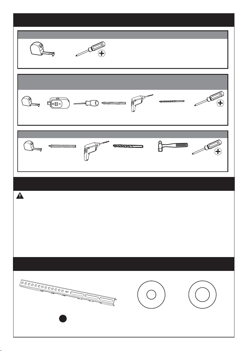
Supplied Parts and Hardware
WARNING: This product contains small items that could be a choking
hazard if swallowed.
Before starting assembly, verify all parts are included and undamaged. Do not
use damaged or defective parts. lf you require replacement parts, please
contact our Technical Support line at (877) 419-7832 or customer service at
• PLEASE NOTE: Not all hardware included in this package will be used.
Tools Needed (Not lncluded)
AwlStud Finder
Tape Measure
Tape
Measure
Tape
Measure Pencil
Pencil
1/8in(3mm)
Wood Drill Bit
5/16in(8mm)
Concrete Drill Bit Hammer
Drill
Drill
Phillips
Screwdriver
Phillips
Screwdriver
Phillips
Screwdriver
For safety straps installation into concrete wall
For safety strap installatcon into wood table/furniture and wood stud applications
For TV stand assembly
(B1) x4
M4/M5
Washer
(B2) x4
M6/M8
Washer
Supplied Parts and Hardware for Step 1
x2
TV Bracket
2
03 04 05 06 07 08 09 10 11 12 13 14 15 16 1702

Step 1 Secure the TV Brackets [N] to TV
Select TV Bolts
Only one bolt size fits your TV.
(C1) x4
M4x12mm
Bolt
(C2) x4
M4x30mm
Bolt
(D1) x4
M6x15mm
Bolt
(D2) x4
M6x35mm
Bolt
(E1) x4
M8x25mm
Bolt
(E2) x4
M8x50mm
Bolt
(F1) x8
L2.5mm
Spacer
(F2) x4
L10mm
Spacer
(F3) x4
L22mm
Spacer
Bolts and spacers are shown in actual size.
Bolt length: Verify adequate thread engagement with bolts or bolts/spacers
combination. We recommend thread engagement by at least 5 turns.
-Too short will not hold the TV.
-Too long will damage the TV.
OR OR
Too Short Correct Too Long
M6 M8M4
03 04 05 06 07 08 09 10 11 12 13 14 15 16 1702

PLEASE NOTE: When using the spacers it is important to note that they can be used
in multi-layers (meaning stacked). If you have any difficulty understanding how to
install the TV bolts or spacers, please contact our Technical Support line at
2When attaching the TV brackets to the
back of the TV, ensure the Up Arrows are
pointing to the top of the TV and are
equally centered on the back of the TV.
UP
Height Location #1
Height Location #3
TV Brackets have “three height locations”, which determines the height position
of your TV while attaching your TV on the stand in Step 6 on page 12.
You can choose the proper height.
Bump
See Option C Cables
See Option D Recessed Holes
See Option E
Spacers
Parts Needed if You Have a TV as Shown Below
F1+F1 F1+F2 F1+F3F1+F1+F2 F1+F1+F3 F2+F3 F1+F2+F3 F1+F1+F2+F3
Curved TV
See Option B
Height Location #2
03 04 05 06 07 08 09 10 11 12 13 14 15 16 1702

Option A (For Flat Back TV )
B1/B2
C1/D1/E1
B1/B2
F1/F2/F3
C2/D2/E2
Option B (For Curved Back TV)
Option C (For TV with A “Bump”)
B1/B2
C2/D2/E2
F1/F2/F3
Phillips Screwdriver
(Not lncluded)
Refer back to Spacer Instructions
on Page 5, If needed
Spacers must be large enough so TV bracekts are flush (NO GAP) on bump
Refer back to Spacer Instructions
on Page 5, If needed
Spacers must be tall enough so that the curve on the back of the TV will not
interfere with the mounting plate.
03 04 05 06 07 08 09 10 11 12 13 14 15 16 1702

Option D (for TV with Cable Interference)
Option E (For Recessed Holes )
For cable interference, use spacers [F1], [F2] and [F3] to
create extra space between the TV and TV brackets. Phillips Screwdriver
(Not lncluded)
Refer back to Spacer Instructions
on Page 5, If needed
Refer back to Spacer Instructions
on Page 5, If needed
F1/F2/F3
C2/D2/E2
B1/B2
F1/F2/F3
The spacer need to fill in the recessed holes on the basis of the TV so that
the TV brackets are as close to the TV as possible.
B1/B2
C2/D2/E2
2
2
03 04 05 06 07 08 09 10 11 12 13 14 15 16 1702
I
3
5
G
I
J
Table
3
7
7
Step 2-1
Step 2-2
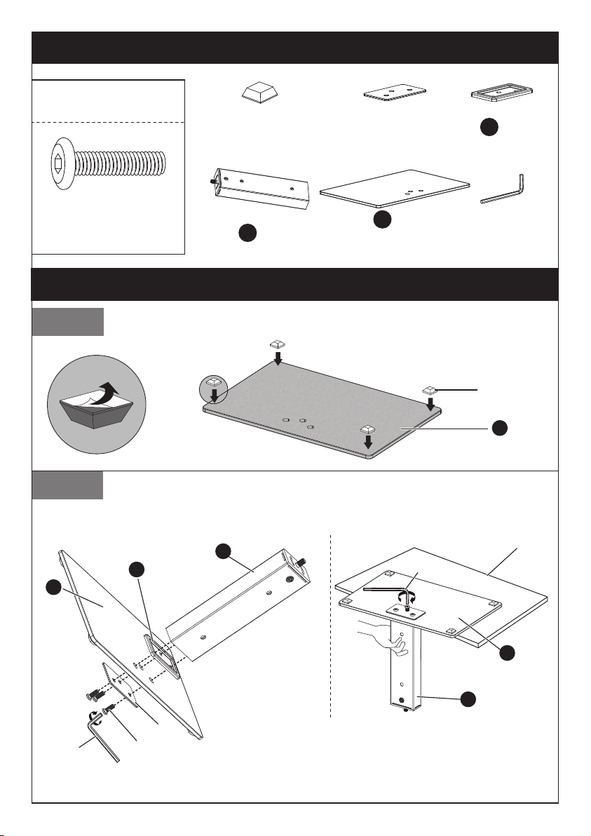
(H) x4
Foot Pad
(J) x1
Reinforcement
Plate
Supplied Parts and Hardware for Step 2
This bolt is shown in
actual size.
(G) x3
M8x25mm Bolt (I) x1
13/64in(5mm)
Allen Key
Place foot pads [H] to the painted side of the tempered glass
base [7] in the corners.
Step 2 Assemble the Base
Connect the lower support pillar [3] to tempered glass base [7].
When assembling the pillar, ensure the side of the
reinforcing plate [J] with paper is facing the glass
base [7].
Do Not overtighten the bolts [G].
x1
Lower Support Pillar
3
x1
Tempered
Glass Base
7
x1
Trim Ring
5
H
7
03 04 05 06 07 08 09 10 11 12 13 14 15 16 1702

Step 3 Connect the Upper Support Pillar [4] to Lower Support Pillar [3]
Supplied Parts and Hardware for Step 3
(L) x1
D10.5xD30.0x2.5mm
Washer
(M) x2
D10.5xD28.0x1.0mm
Plastic Washer
x1
Upper Support Pillar
4
(K) x1
M10 Nut
(N) x1
M6-M10
Wrench
x2
Cable Clip
8
8
K
L
M
N
4
3
Tighten the nut to keep
the swivel tight.
03 04 05 06 07 08 09 10 11 12 13 14 15 16 1702
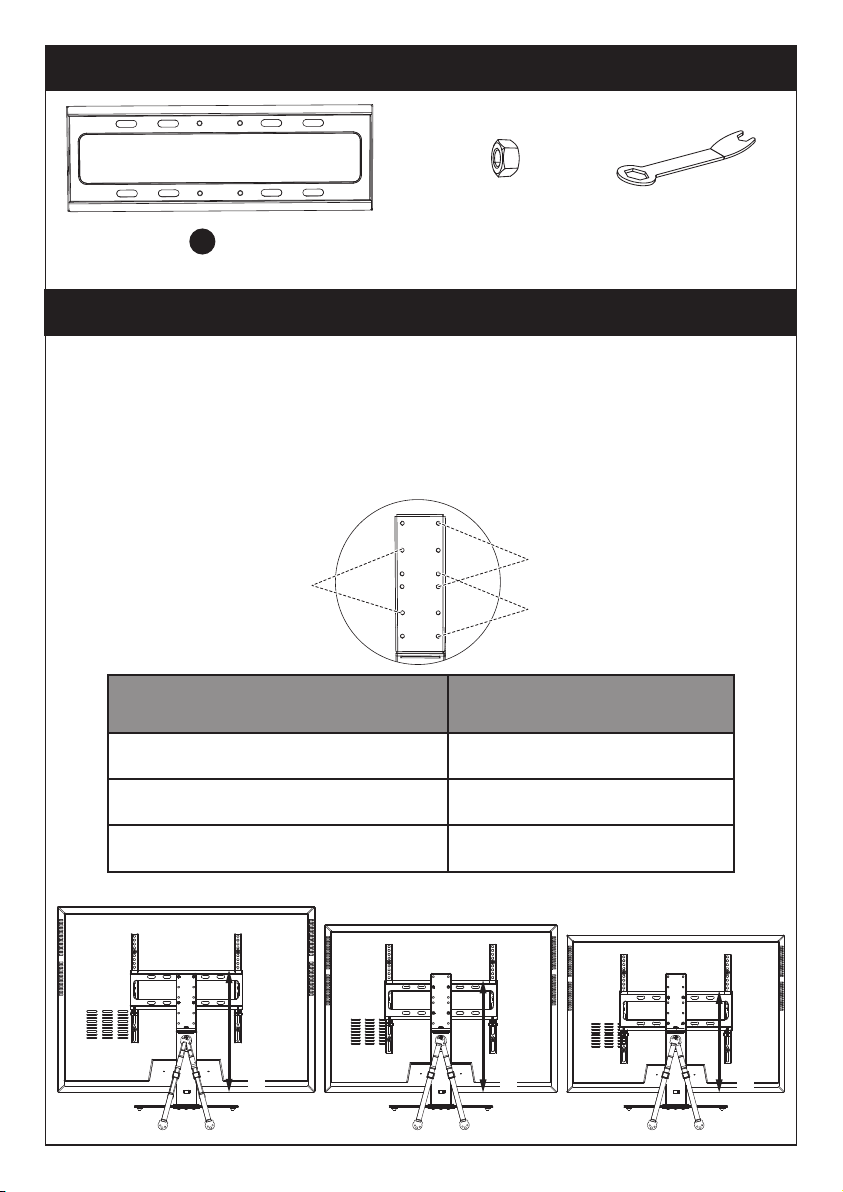
Distance from the hooks on the TV
Brackets to the bottom of the TV
Recommended TV Mounting
Plate Location
17" to 18 1/2"
15 1/2" to 17"
Less Than 15 1/2"
Location #1
Location #2
Location #3
Note: Before attaching the TV Mounting Plate to the pillar, measure the
distance from the upper hook on the TV Bracket to the bottom of the TV.
Then refer to chart below for the recommended mounting location. To add an
additional 2” of space between your TV and the base, use the lower hooks
located on the TV Brackets. We always recommend using the lowest possible
attachment location for the safest assembly.
Step 4 Connect the TV Plate [1] to Upper Support Pillar [4]
Supplied Part and Hardware for Step 4
x1
TV Plate
1(O) x4
M6 Nut
(N) x1
M6-M10
Wrench
Mounting Location #1
Mounting Location #2
Mounting Location #3
Location #1
Location #2
Location #3
03 04 05 06 07 08 09 10 11 12 13 14 15 16 1702

Step 5 Secure the Safety Straps [P] to Lower Support Pillar [3]
Supplied Part and Hardware for Step 5
(P) x2
Safety Strap
This bolt is shown in actual
size.
(Q) x1
M8x15mm Bolt
N
O
Q
P
1
4
3
Phillips Screwdriver
(Not lncluded)
3
03 04 05 06 07 08 09 10 11 12 13 14 15 16 1702
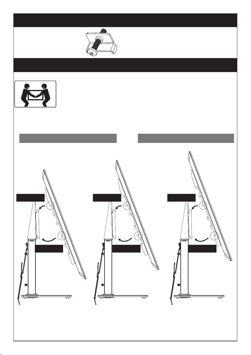
Step 6 Attach TV to the TV Plate [1] and Manage the Wires
Supplied Part for Step 6-3
We recommend always having a second person to help during
this step. TV can be heavy and awkward to place on the stand.
It is best to have 2 people lift the TV from the sides so they
can see the attachment points.
OROR
NOTE: Attached TV Brackets
to the TV Mounting plate on
the lowest placement that
allows for TV to fit.
Step 6-1 Hang the TV with brackets to the TV plate.
Step 6-2 Push the bottom of the TV to TV plate.
Smaller TV’s use the upper hooks Larger TV’s use the lower hooks
(K1) x2
Safety Lock
Step 6-1
Step 6-2
Step 6-1
Step 6-2
Step 6-1
Step 6-2
03 04 05 06 07 08 09 10 11 12 13 14 15 16 1702

Insert the safety locks [K1] into the upward facing hooks at the
midway to lower part of the TV bracket. Please note this is where the lower
part of the TV bracket meets the TV plate. Then tighten the bolts of the safety
lock [K1] until the bolts touch the TV plate.
Supplied Hardware for Step 7A
x2
Z1
x4
Z2
x2
Z3
NOTE: Make sure the bolt is tighten
behind the TV mounting plate.
Step 6-3
Phillips Screwdriver
(Not lncluded)
Screw M5X25mmScrew M5X60mm M5 Washer(BK)
For wooden table furniture/wood stud installation.
Manage the wires
K1
K1
03 04 05 06 07 08 09 10 11 12 13 14 15 16 1702

Secure The Safety Straps With TV Stand Against The Wall
For wood stud installation, follow STEP 7B
For solid concrete or concrete block installation, follow
STEP 7C
For wooden table furniture installation, follow STEP 7A
X
Step 7A
For Wooden Table furniture Installation
Pencil
(Not lncluded) 1/8in(3mm)
1in(25mm)
NOTE: For the safest possible installation, we recommend using the included safety
straps. By doing so, you will greatly reduce the possibility of a TV Tip Over.
● DO NOT USE ANCHOR [Z4] FOR THIS STEP!
NOTE: It is necessary to predrill a pilot hole to avoid splitting the
wood. Being careful not to damage your furniture.
Caution: The mounting surface must be thicker than 1in(25mm).
It is reccommended that
the safety straps be
mounted at least 12” apart. Phillips Screwdriver
(Not lncluded)
1/8in(3mm)
1in(25mm)
Z2
X
03 04 05 06 07 08 09 10 11 12 13 14 15 16 1702

OR
Awl
(Not lncluded)
Stud Finder
(Not lncluded)
Pencil
(Not lncluded)
Step 7B
For Wood Stud Installation
● DO NOT USE ANCHOR [Z4] FOR THIS STEP!
● Any material covering the wall must not exceed 5/8in(16mm)
● Nominal wood stud size: common 2 x 4in(51 x 102mm)
minimum 1½ x 3½in(38 x 89mm)
● Stud center must be verified by using an awl or stud finder
NOTE: Each strap must be
mounted to a separate stud. Phillips Screwdriver
(Not lncluded)
Z1
2 1/2in(60mm)
1/8in(3mm)
1/8in(3mm)
Wood Drill Bit
X
Z3
03 04 05 06 07 08 09 10 11 12 13 14 15 16 1702
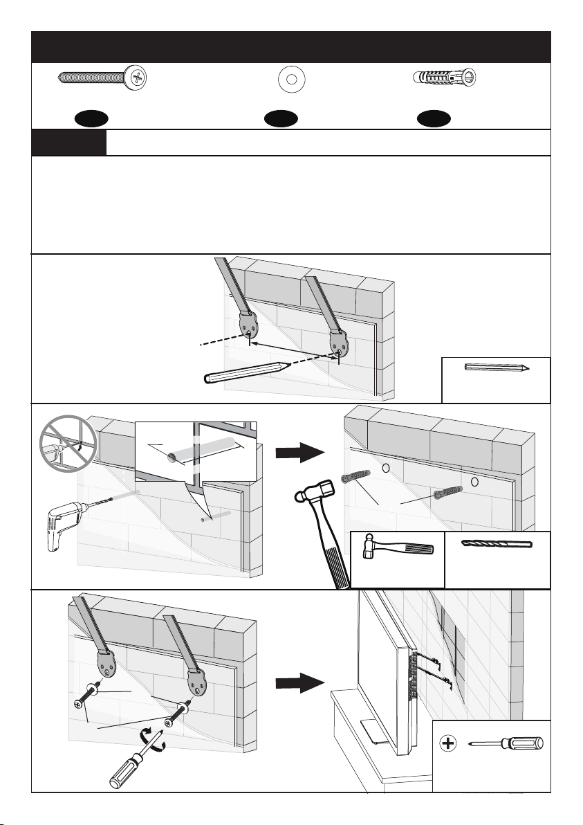
Step 7C For Solid Concrete or Concrete Block Installation
● Must use wall anchor [Z4] for this step
● Any material covering the wall must not exceed 5/8in(16mm)
● Minimum solid concrete thickness: 203mm(8in)
● Minimum concrete block size: 203 x 203 x 406mm(8 x 8 x 16in)
● Never drill into the mortar between blocks
Wall Anchor 8x50mm
Pencil
(Not lncluded)
Z4
5/16in(8mm)
Concrete Drill Bit
Hammer
(Not lncluded)
Supplied Hardware for Step 7C
x2
Z1
x2
Z3
x2
Z4
Screw M5X60mm M5 Washer(BK)
Phillips Screwdriver
(Not lncluded)
Z1
Z3
12in(305mm)
2 9/16in(65mm)
5/16in(8mm)
03 04 05 06 07 08 09 10 11 12 13 14 15 16 1702
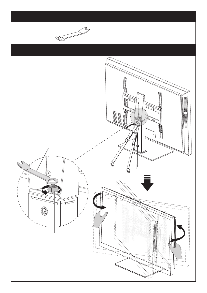
Step 8 Swivel Adjustment
The TV can be swivelled manually. If
it is too hard to swivel, please follow
these steps:
1. Loosen the nut [B] using wrench
[J].
2. Swivel the TV to your desired
swivel angle.
3. Tighten the nut [B] using wrench
[J] to fix the TV in place.
NOTE: Please do not over-loosen or
over-tighten the nut [B].
J
B
Supplied Hardware for Step 8
(N) x1
M6-M10
Wrench
03 04 05 06 07 08 09 10 11 12 13 14 15 16 1702

Avant de commencer, vérifions que ce support est parfait pour vous!
Consignes de sécurité importantes
ATTENTION : Évitez risques de blessures et de dommages matériels!
N'utilisez pas ce produit à des fins qui ne sont pas explicitement spécifiées
dans ce manuel. Ne dépassez pas la capacité de charge. Nous ne sommes
pas responsables des dommages ou blessures causés par un montage
incorrect, un assemblage incorrect ou une utilisation inappropriée.
Veuillez lire attentivement toutes les instructions avant de tenter l'installation.
Si vous ne comprenez pas les instructions, avez des inquiétudes ou des
questions, veuillez contacter notre ligne d'assistance technique au (877)
88lbs/
39.9kg
1
Mesurez le modèle VESA de votre téléviseur:
Minimum: 100x100mm/4x4 pouces (LxH)
Maximum: 400x400mm/15.7x15.7 pouces (LxH)
1
L
H
Béton massif ou
bloc de béton
NE PAS installer dans une cloison sèche seule.
Montants en bois
(avec cloison sèche)
Pour les installa-
tions de sangles
de sécurité, vous
devrez vérifier la
construction de
votre mur.
Si ce support TV n'est PAS compatible, veuillez contacter notre ligne d'assistance
technique au (877) 419-7832 ou notre service clientèle à l'adresse
Si votre téléviseur ne se situe pas entre les
mesures minimum et maximum, n'utilisez
pas ce produit.
Si votre téléviseur pèse plus de 88 lb,
n'utilisez pas ce produit.
19 20 21 22 23 24 25 26 27 28 29 30 31 32 3318
Pièces et matériel fournis
AVERTISSEMENT: Ce produit contient des petits objets susceptibles de
présenter un risque d'étouffement en cas d'ingestion.
Avant de commencer l'assemblage, vérifiez que toutes les pièces sont inclus-
es et en bon état. N'utilisez pas de pièces endommagées ou défectueuses. Si
vous avez besoin de pièces de rechange, veuillez contacter notre ligne d'as-
sistance technique au (877) 419-7832 ou notre service clientèle à
• VEUILLEZ NOTER: le matériel inclus dans cet ensemble ne sera pas utilisé
en totalité.
Outils nécessaires (non inclus)
Ailette
Détecteur
de goujons
Mètre
ruban
Mètre
ruban Crayon
Crayon
1/8 pouces (3mm)
Mèche à bois
5/16 pouces (8mm)
Foret à béton Marteau-piqueur
Foreuse
Foreuse
Tournevis
Phillips
Tournevis
Phillips
Pour l'installation de sangles de sécurité dans un mur en béton
Pour l'installation d'une sangle de sécurité dans les tables/meubles en bois et les
montants en bois.
Mètre ruban Tournevis Phillips
Pour le montage du support TV
(B1) x4
M4/M5
Rondelle
(B2) x4
M6/M8
Rondelle
Pièces et matériel fournis pour l'étape 1
x2
Support de téléviseur
2
19 20 21 22 23 24 25 26 27 28 29 30 31 32 3318

L'étape 1 Fixez les supports du téléviseur [N] sur le téléviseur
Sélectionnez les boulons TV
Une seule taille de boulon convient à votre téléviseur.
(C1) x4
M4x12mm
boulon
(C2) x4
M4x30mm
boulon
(D1) x4
M6x15mm
boulon
(D2) x4
M6x35mm
boulon
(E1) x4
M8x25mm
boulon
(E2) x4
M8x50mm
boulon
(F1) x8
L2.5mm
Entretoise
(F2) x4
L10mm
Entretoise
(F3) x4
L22mm
Entretoise
REMARQUE : Les boulons et les entretoises sont représentées à leur taille réelle.
Longueur de la boulon : Vérifiez que le filetage est correctement engagé avec
les boulons ou la combinaison boulons/entretoises. Nous recommandons un
engagement du filetage sur au moins 5 tours.
- Trop court, le téléviseur ne sera pas maintenu.
- Trop long, le téléviseur sera endommagé.
OU OU
Trop court Correct Trop long
M6 M8M4
19 20 21 22 23 24 25 26 27 28 29 30 31 32 3318
Table of contents
Languages:
Other ErgoAV TV Mount manuals

ErgoAV
ErgoAV ERMTM1-01B User manual

ErgoAV
ErgoAV ERDHM2-01B User manual

ErgoAV
ErgoAV ERMTM2-01B User manual

ErgoAV
ErgoAV ERTSS2-01B User manual

ErgoAV
ErgoAV ERMCM1-01B User manual

ErgoAV
ErgoAV ERMTS1-01B User manual

ErgoAV
ErgoAV ERMTM2-01B User manual

ErgoAV
ErgoAV ERMTL1-01B User manual

ErgoAV
ErgoAV ERMMS1 -01 B User manual

ErgoAV
ErgoAV ERDHM1-01B User manual
Popular TV Mount manuals by other brands


Vivo
Vivo MOUNT-M-MM070R instruction manual

Gembird
Gembird MA-DA1-02 user manual

Vivo
Vivo MOUNT-VC55A instruction manual

Technimount System
Technimount System PRO 150 Series user guide

PEERLESS
PEERLESS SmartMount SF670 and assembly Installation and assembly manual

Omnimount
Omnimount ULPC-X instruction manual


