ErgoAV ERDHM2-01B User manual

1 2 3 4
2 431
D
E
C
B
A
F
E
D
C
B
A
(.XXX)
##
.XXX
##
ERDHM2-01B-
Manual(英法西)-XX
0-30 ±1
30-150 ±2
150-300 ±3
300-450 ±4
>450 ±5
00
XXX-XXXXX-XX
1 1
技术要求:
1、材质:封页105g 铜板纸;内页80g双胶纸
2、展开尺寸:A4,如图所示装订成型为A5,44P
3、颜色:单色
4、印刷:印刷图档见后续页,双面印刷
5、装订方式:骑马钉
Lia
2023/06/01
刀模线:
内折线:
注:此页为技术说明,非印刷内容
297mm
210mm
装订效果图:
展开尺寸图:
深圳市倍思奇创
新科技有限公司
封
面
封
底
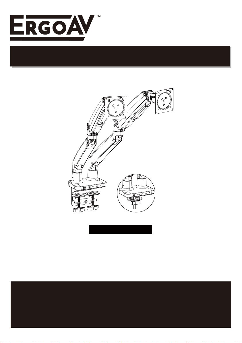
(A)
Dual Monitor Desk Mount Instruction Manual
Thank You for Choosing this ErgoAV Product!
At ErgoAV, we want to add value to your AV experience by providing the highest
quality products and services in the industry. If you have any concerns or
comments, please contact us.
ErgoAV Customer Care
phone: (877) 419-7832
email: [email protected]
website: www.ergoav.com
address: 9501 Louisiana Ave N, #200, Brooklyn Park, MN 55445
Model: ERDHM2-01B
English pages French pages Spanish pages

• Please carefully read all instructions before attempting installation. If you do not understand the
instructions or have any concerns or questions, please contact Technical Support at
CAUTION: Avoid potential personal injuries and property damage!
• Do not use this product for any purpose that is not explicitly specified in this manual. Do not exceed
weight capacity. We are not liable for damage or injury caused by improper mounting, incorrect
assembly or inappropriate use.
• This product contains gas assist arms which are under pressure. Do not puncture these arms or
expose the arms to high heat.
• If the product arrives defective or is missing parts, please contact ErgoAV Customer Support at
• Do Not use this product on desks made of particle board or other soft woods.
• The information contained in this manual does not cover all possible conditions or variables in
relation to the install of this product.
Check the VESA Pattern of Your Monitor before the Installation
Important Safety Information
If your monitor's VESA Pattern is smaller than 75mm x 75mm/3” x 3” or greater than
100mm x 100mm/4” x 4”, this mount is NOT COMPATIBLE with your monitor.
find a compatible mount.
Weight Restrictions
4.4~22 lbs.
MAX
Per Arm
(2.0~10.0 kg)
If your monitor weighs
more, this mount is
NOT compatible. Monitor
should not exceed
maximum listed weight.
WARNING
DO NOT exceed the maximum weight indicated. This mounting
system is intended for use only within the weight range listed. Use
with products heavier than the maximum weight limit may result in
failure of the mount, causing potential damage and or injury.
It is the responsibility of the installer to verify the total weight of
the monitors and any accessories attached. Do Not exceed the
weight limit listed.
W
HMinimum: 75mm x 75mm/3”x 3”(WxH)
Maximum: 100mm x 100mm/4”x 4”(WxH)
Measure Your Monitor's VESA Pattern:
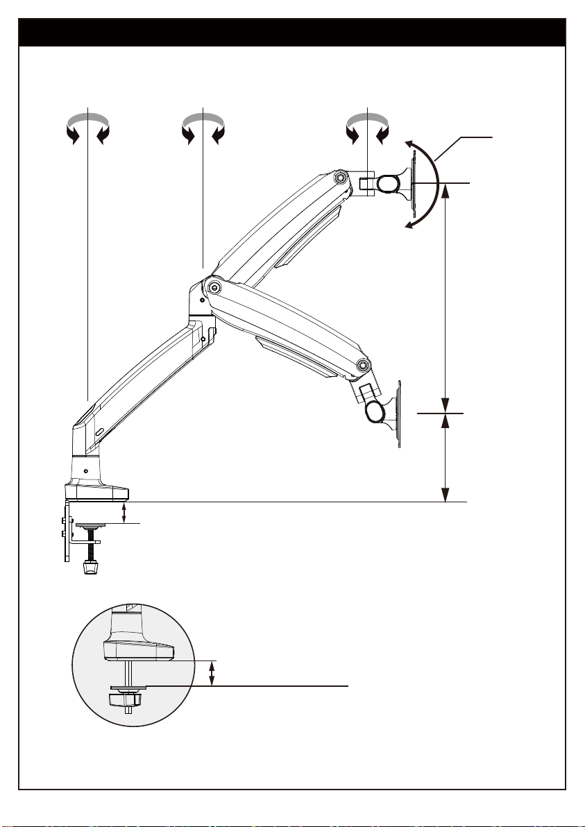
Product Features
Grommet Mounting
for grommet bolt
0.79” ~ 3.54”
(20~90mm)
360° 360°
15.2”
(385mm)
7.3”
(185mm)
+45°
180°
C-Clamp Mounting for table edge
0.79” ~ 3.54” (20–90mm)

DO NOT adjust tension without monitor attached.
1. Verify the weight of your monitor (including accessories) is between
4.4 ~ 22 Ibs (2.0~10.0 kg).
2. Monitor weight information can be found within its box or manual.
3. Ensure monitor has been securely attached to the mount.
TENSION ADJUSTMENT SHOULD BE DONE ONLY
AFTER MOUNT INSTALLATION
Attention
WARNING:
Gas Spring Arm is under pressure and should be handled with care.
Failure to follow the instructions may result in damage to the mount and/or
personal injury.
Supplied Parts and Hardware
WARNING: This product contains small items that may pose a choking hazard.
Before starting assembly, verify all parts are included and undamaged. Do not use
damaged or defective parts. lf you require replacement parts, please contact Technical
Support at (877) 419-7832 or Customer Service at [email protected] to find a
compatible mount.
• NOTE: Not all hardware included in this package will be used.
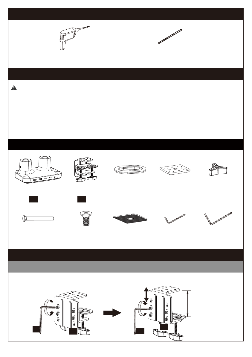
Supplied Parts and Hardware for Step 1
Electric Drill (Optional)
Drill Bit (Optional)
3/8–1 1/16" (10–27mm)
Tools Needed (Not lncluded)
Base
01
x 1
Step 1 Attach to Desk Mounting Surface
C-Clamp
02
x 1
Bolt M6 x 12mm
[B1] x 4
Rubber Pad
[C] x 1
Medium Allen Key
5/32” (4mm)
[L1] x 1
Locking Plate
[A1] x 1
Locking Plate
[A2] x 1
Butterfly Nut
[A3] x 1
Grommet Bolt
[A4] x 1
Option A: For Clamp Mounting
1A-1 Remove the pre-installed bolts and detach the C-clamp from the brace. Reattach through
the pair of holes with the best clamping range for your desk thickness.
Large Allen Key
3/16” (5mm)
[L2] x 1
Maximum
thickness:
3.54” (90mm)
L2 L2 02
02
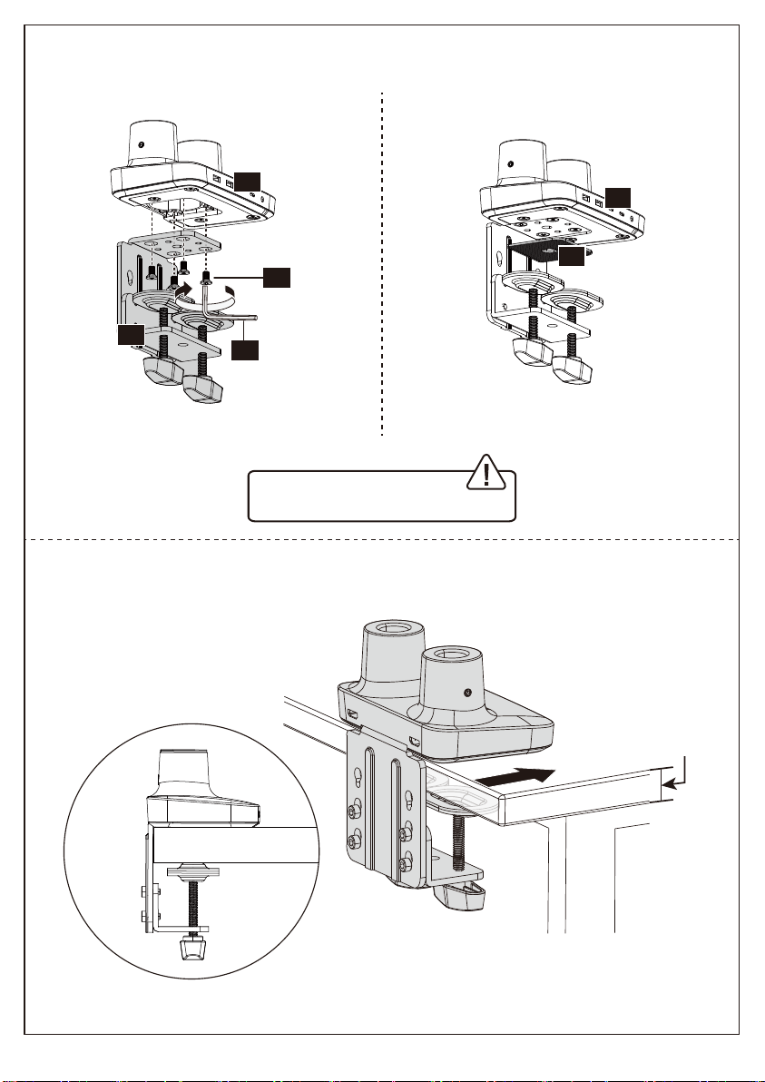
1A-2 Attach the C-clamp brace to the
Base [01] using Bolts [B1].
1A-3 Install the Rubber Pad [C] on the
Base [01].
WARNING:
Ensure bolts are secured firmly.
1A-4 After pushing the clamp fully onto the desk, rotate the knob until the C-Clamp [02]
is secured firmly to the underside of desktop.
0.79”–3.54”
(20–90mm)
0.79”–3.54”
(20–90mm)
L1
B1
02
01
01
C

Option B: Existing Grommet Hole Installation
A4
A2 C
ATTENTION:
Ensure the grommet
bolt is threaded
securely to the base.
L1
B1
3/4" ~ 3 1/2"
20~90mm
0.79”–3.54”
20~90mm
NOTE: If your desk has an existing grommet
hole with a plastic cover, remove it before
installation.
A1
A4
A3
Rotate Butterfly Nut [A3] until the Locking Plate [A1] is firmly secured to the underside of
your desk.

L1
B1
A4
A2 C
ATTENTION:
Ensure the grommet
bolt is threaded
securely to the base.
Rotate Butterfly Nut [A3] until the Locking Plate [A1] is firmly secured to the underside of
your desk.
Option C: Self Drilled Grommet Hole Installation
If a hole is needed for grommet installation, be sure to leave at least 2” from the edge
of desktop and mark where the hole will be drilled. Use either a 7/16” or 7/8” drill bit
for this step.
7/16" ~ 7/8"
11-22cm
Electric Drill
(Not Included)
NOTE: The hole
should be at least
50mm (2") from
the edge of the
desk.
NOTE: The hole
should be at least
50mm (2") from
the edge of the
desk.
3/4" ~ 3 1/2"
20~90mm
0.79" ~ 3.54"
20~90mm
A1
A4
A3

Supplied Parts and Hardware for Step 2
Small Allen Key
1/8” (3mm)
[L3] x 1
Arm Extender
03
x 2
Arm
04
x 2
2-1 Push the Arm Extender [03] into the base, and then the Arm [04] onto the Arm
Extender [03].
2-2 Tighten the set screws on both sides of the arm joints. Do not overtighten the set
screws as this may affect the rotation of the arm.
Step 2 Attach the Arm Sections
Supplied Parts and Hardware for Step 3
Large Allen Key
3/16” (5mm)
[L2] x 1
Monitor Plate
05
x 2
Bolt
M8 x 38mm
[D1] x 2
Washer
16 x 8.2 x 1.5mm
[D2] x 2
03
04
04
03
03
L3
L3

Supplied Parts and Hardware for Step 4
Slide the Monitor Plate [05] sideways into the slot at the end of the Arm [04]. Fasten with
Bolt [D1] and Washer [D2].
Step 3 Attach the Monitor Plate
L2
05
04
Washer
10 x 4.5 x 1.0mm
[E1] x 8
Spacer
L13mm
[H1] x 8
Bolt
M4 x 12mm
[F1] x 8
Bolt
M4 x 30mm
[G1] x 8
Large Allen Key
3/16” (5mm)
[L2] x 1
D2
D1
Step 4 Attach the Monitor to the Arm
Only one size bolt fits your monitor.
Select Monitor Bolts
M4

L3
F1
F1
E1 E1 0.1–0.2" (3–5mm)
spacing left
Option A (For Flat Back Monitor)
4A-1 Thread two Bolts [F1] with Washers [E1] into the top holes until about 0.1–0.2"
(3–5mm) of space is left between monitor back and washer.
4A-2 Hang the monitor from the monitor plate with the top two Bolts [F1] (see Fig. A or
Fig. B). Screw the remaining two Bolts [F1] into the bottom holes (see Fig.C).
Tighten all Bolts [F1] evenly.
Fig. A
For Monitor Hole Pattern:
100 x 100mm (3.9 x 3.9”)
For Monitor Hole Pattern:
75 x 75mm (3 x 3”)
Fig. B
Fig. C
F1
F1
E1 E1
F1 E1
F1 E1
Turn clockwise to thread
Bolt length: Verify adequate thread engagement with bolts or bolts / spacers combination.
We recommend thread engagement of at least 5 turns.
-Too short will NOT hold the monitor.
-Too long will damage the monitor.
Too Long
Correct Correct
Too Short
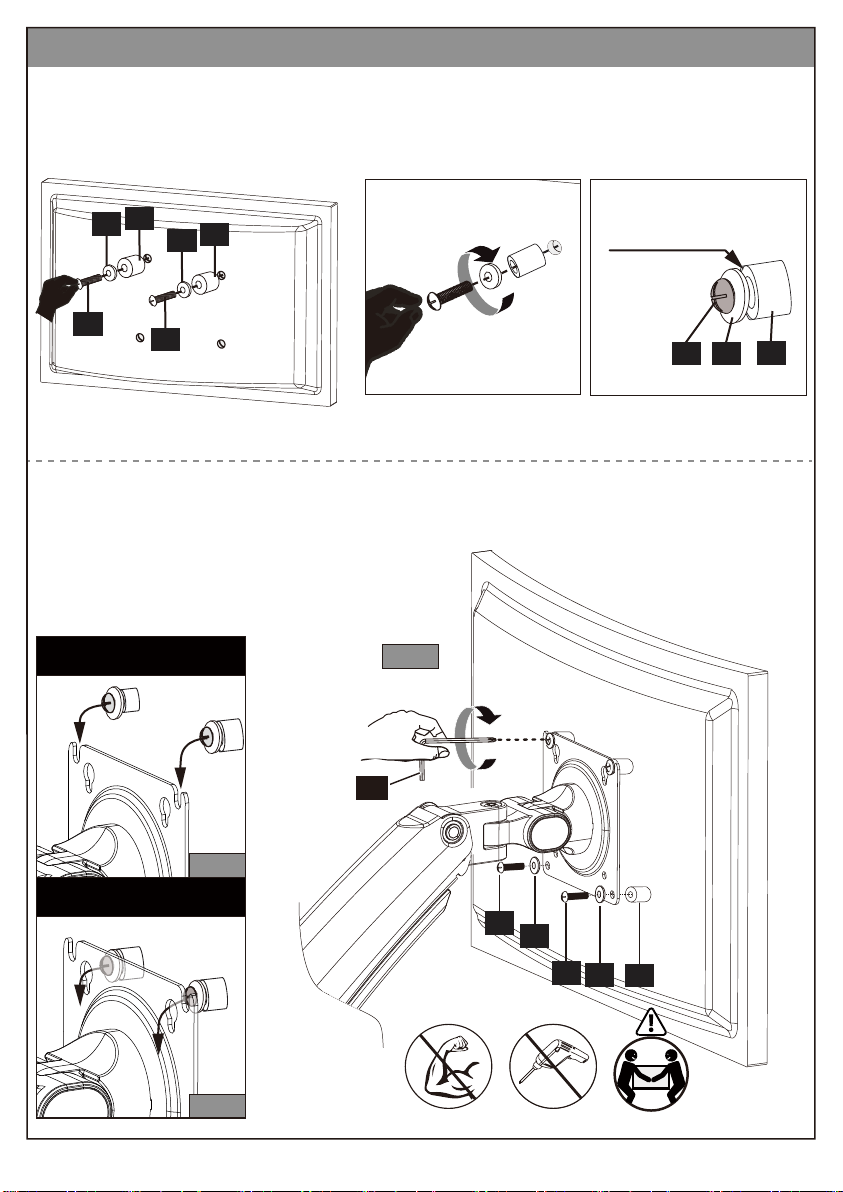
Fig. C
H1
E1
G1 E1
L3
G1
Fig. A
For Monitor Hole Pattern:
100 x 100mm (3.9 x 3.9”)
For Monitor Hole Pattern:
75 x 75mm (3 x 3”)
Fig. B
Option B (For Curved Back Monitor)
4B-1 Slide the Washers [E1] and Spacers [H1] over the Bolts [G1]. Turn the top two
Bolts [G1] CLOCKWISE until about 0.1–0.2" (3–5mm) of space is left between the
Washer [E1] and the Spacer [H1].
4B-2 Hang the monitor from the monitor plate with the top two Bolts [G1] (see Fig. A or
Fig. B). Place the Spacers [H1] between the monitor plate and back of monitor.
Screw the remaining two Bolts [G1] into the bottom holes (see Fig.C). Tighten all
bolts evenly.
0.1–0.2" (3–5mm)
spacing left
G1 H1
E1
G1
E1 H1
G1
E1 H1

WARNING!
Gas Spring arm is under pressure and should
be handled with care. Failure to follow the
instructions may result in damage to the
mount and/or personal injury.
Step 5 Adjust the Gas Spring Tension
Note: Ensure the arm is held in a
horizontal position (parallel to desktop)
during adjustment. Failing to do so may
result in difficulty adjusting or potential
damage to the mount.
5-1 If the gas spring arm RISES with the monitor
attached, hold the arm in a horizontal position
while using the large Allen Key [L2] to turn the
adjustment bolt CLOCKWISE, REDUCING the
arm tension.
5-2 If the gas spring arm LOWERS with the
monitor attached, hold the arm in a horizontal
position while using the large Allen Key [L2] to
turn the adjustment bolt COUNTER-clockwise,
INCREASING the arm tension.
Supplied Hardware for Step 5
L2
Clockwise to
REDUCE tension
Counter-clockwise
to INCREASE tension
Large Allen Key
3/16” (5mm)
[L2] x 1

Incorrect orientation Correct orientation
Supplied Hardware for Step 7
Step 7 Adjust the Monitor to Proper Tilt Angle
Use fingernail or tool to open the cover easily. Slightly loosen the bolt with large Allen Key
[L2]. Tilt monitor to your desired position. Re-tighten the bolt with large Allen Key [L2] to
hold monitor in desired position.
Step 6 Rotation Restriction
To ensure proper stability, do not position monitor behind base. Monitor and arms should
remain over the desktop. Failure to do so may cause instability, resulting in property
damage or injury.
Large Allen Key
3/16” (5mm)
[L2] x 1
L2

Supplied Hardware for Step 8 and Step 10
Small Allen Key
1/8” (3mm)
[L3] x 1
Large Allen Key
3/16” (5mm)
[L2] x 1
Step 9 Rotation Adjustment
Step 8 Swivel Adjustment
Turn adjustment set screw
CLOCKWISE to INCREASE
the swiveling tension.
Turn adjustment set screw
COUNTER-CLOCKWISE to
REDUCE the swiveling
tension.
L3
180°180°
360°360°
360°360°
Firmly hold monitor at
edges and rotate from
Landscape to Portrait mode.
360° Rotation
WARNING:
Ensure bolts are secured firmly
before rotation.
WARNING:
Do not overtighten or
overloosen the bolts.
L3
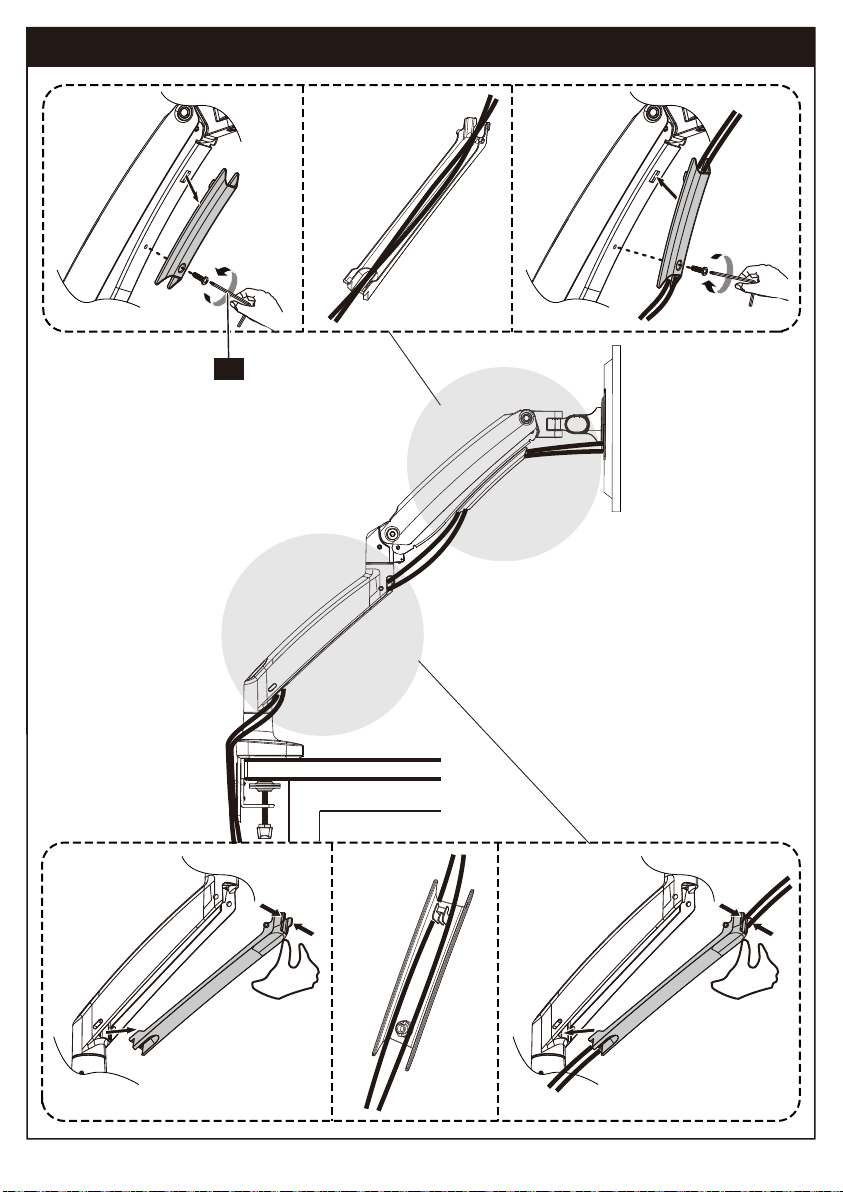
Step 10 Route Cables along the Arm
①
②
⑤
④
③
①
②
⑤
④
③
L2

1&2
3
4
5
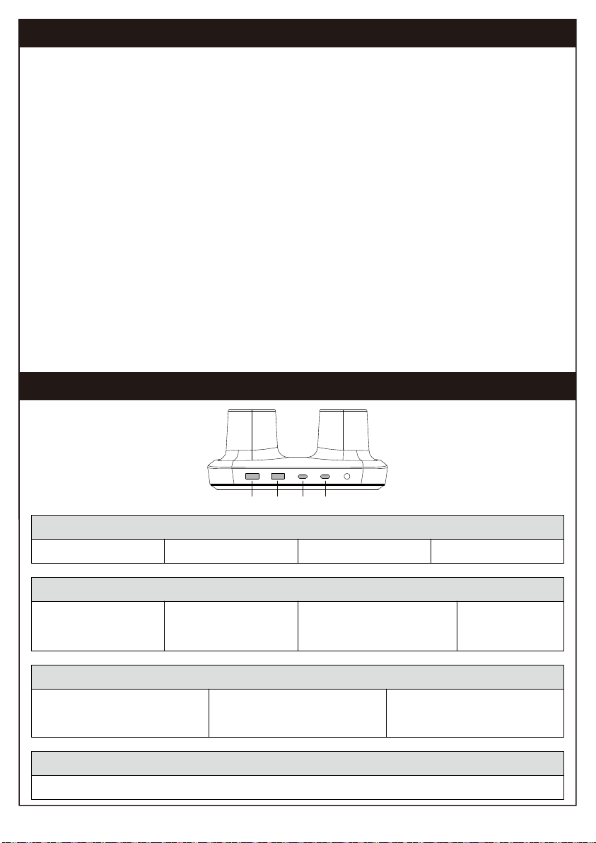
Introduction of the Docking Station
• USB-A 3.0. Used to connect to USB Devices to transfer files.
• Output 900mA, USB2.0 500mA.
• Ability to charge smaller devices.
• 3.5 mm AUX output. Connect earphones or other audio devices.
7
8
9
• 1x RJ45 Ethernet Port. Connection speeds of up to 1Gbps.
• Uses CAT5 or CAT6 cable.
6
• Media streaming up to 4k resolution via HDMI.
• This port is capable of up 4k streaming at 60Hz. (HDMI-1 is HDMI 2.0.)
• Media streaming up to 4k resolution via HDMI.
• This port is capable of up 4k streaming at 30Hz. (HDMI-2 is HDMI 1.4.)
• The 30HZ HDMI port needs to install the drive to use two screens.
• Supports up to 75W USB-C for Laptops, Tablets and Phones.
• UBS C port referenced as port No. 4 is where your laptop/tablet should be
plugged in to utilize the hub.
• After connecting your USB C cable to the Hubs corresponding port, your
computer will automatically detect the file ErgoAV by displaying an external
drive on your desktop.
• USB-C Data Port (7.5W). Transfer files up to 5Gbps.
• Charge devices via the 7.5W USB-C port.
• 100W PD Input Port.
• 100W PD input is the max power this port can accept.
Power Distribution of the Docking Station
System Requirements for Monitor Mounts with Dock
4k@60Hz Operating System(Port 8):
• Win10, Win11 or later
• Mac OS 10.12~13.3.1 versions (support M1 & M2 & Intel chip) or later
• Chrome OS 48.0.2564.82 or later
• iPad OS 12 or later
• Android 9.0 or later
• Linux Kernel 4.6 or later
(Apples website that clearly describes your Apple Intel/Silicon computers capabilities: https://sup-
port.apple.com/en-us/HT213503)
4k@30Hz Operating System(Port 9):
• Win10, Win11 or later
• Mac OS 10.12~13.3.1 versions (support M1 & M2 & Intel chip) or later
(Windows and macOS require driver installation to use this port.)
Compatible Devices Include:
Only compatible with laptops/computers and tablets that have a USB type C connection.
Environment:
32° to 104° F / 0° to 40° C
A1 A2 C1 C2
Two Ports:
C1: 7.5W Max
A1 or A2: 7.5W Max
C2: 75W Max
A1 or A2: 7.5W Max
C1: 7.5W Max
C2: 75W Max
A1 & A2:
One of the ports 7.5W Max,
total 10.8W Max
Single Port:
C1: 7.5W Max C2: 75W MaxA1:7.5W Max A2: 7.5W Max
Three Ports:
C1: 7.5W Max C2: 75W Max
A1 or A2: 7.5W Max
C1: 7.5W Max
A1 & A2: One of the ports 7.5W
Max, total 10.8W Max
C2: 75W Max
A1 & A2: One of the ports 7.5W
Max, total 10.8W Max
C1: 7.5W Max C2: 75W Max A1 & A2: One of the ports 7.5W Max, total 10.8W Max
Four Ports:

9501 Louisiana Ave N, #200, Brooklyn Park, MN 55445
ErgoAV Customer Care
Phone (877) 419-7832
At ErgoAV, we strive to provide the highest value products.
We want to support your purchase.
If you have questions, concerns,
or feedback please let us know!
www.ergoav.com
XXX-XXXXX-XX Rev00(A)
Electric Standing Desk Tabletop TV StandsTV Mount
Table of contents
Other ErgoAV TV Mount manuals

ErgoAV
ErgoAV ERTSS2-01B User manual

ErgoAV
ErgoAV ERTSM2-01B User manual

ErgoAV
ErgoAV ERMTL1-01B User manual

ErgoAV
ErgoAV ERDHM1-01B User manual

ErgoAV
ErgoAV ERMTS1-01B User manual

ErgoAV
ErgoAV ERMMS1 -01 B User manual

ErgoAV
ErgoAV ERMTM2-01B User manual

ErgoAV
ErgoAV ERMCM1-01B User manual

ErgoAV
ErgoAV ERMTM2-01B User manual

ErgoAV
ErgoAV ERMTM1-01B User manual
Popular TV Mount manuals by other brands


Rapid video mounts
Rapid video mounts RVM-75FM150 instruction manual

PDi
PDi PD251-035 installation instructions

Sony
Sony KDL-32ML130 - 32" Bravia M-series Digital Lcd... instructions

Philips
Philips SQM6375/27 user manual

Atdec
Atdec AWM-BT installation guide

cabstone
cabstone CAB EASYFIX U-Slim XL user manual