ErgoAV ERTSS2-01B User manual

Model: ERTSS2-01B
Table Top TV Stand Instruction Manual
V1.0
THANK YOU FOR CHOOSING THIS ERGOAV PRODUCT!
At ErgoAV, we want to add value to your AV experience by providing the highest
quality products and services in the industry. If you have any concerns or
comments, please contact us.
ErgoAV Customer Care
Phone (877) 419-7832 M-F 8am to 8pm CST
email: [email protected]
website: www.ergoav.com
adress: 9501 Louisiana Ave N, #200 Brooklyn Park, MN 55445
English pages: 02-15 French pages: 16-29 Spanish pages: 30-43

Before getting starting, let's make sure this mount is perfect for you!
IMPORTANT SAFETY INFORMATION
CAUTION: Avoid potential personal injuries and property damage!
Do not use this product for any purpose that is not explicitly specified in this
manual. Do not exceed weight capacity. We are not liable for damage or
injury caused by improper mounting, incorrect assembly or inappropriate use.
Please carefully read all instructions before attempting assembly. If you do
not understand the instructions or have any concerns or questions, please
contact our Technical Support line at (877) 419-7832 or customer service at
44 lbs/
19.96 kg
1
Measure Your TV VESA Pattern:
Minimum: 75 x 75mm/3 x 3 in (WxH)
Maximum: 200 x 200mm/8 x 8 in (WxH)
1
W
H
Solid Concrete
or Concrete Block
DO NOT install into drywall alone.
Wood Studs
(with Drywall)
For safety strap
installations, you will
need to verify your
wall construction.
If this TV stand is NOT compatible, please contact our Technical Support line at
mount.
If your TV is not between the minimum and
maximum measurements, do not use
this product.
If your TV weighs more than 44 lbs,
do not use this product.
02

Supplied Parts and Hardware
WARNING: This product contains small items that could be a choking
hazard if swallowed.
Before starting assembly, verify all parts are included and undamaged. Do not
use damaged or defective parts. lf you require replacement parts, please
contact our Technical Support line at (877) 419-7832 or customer service at
• Please note: Not all hardware included in this package will be used.
Tools Needed (Not lncluded)
AwlStud Finder
Tape Measure
Tape
Measure
Tape
Measure Pencil
Pencil
1/8 in (3mm)
Wood Drill Bit
5/16 in (8mm)
Concrete Drill Bit Hammer
Drill
Drill
Phillips
Screwdriver
Phillips
Screwdriver
Phillips
Screwdriver
For safety straps installation into concrete wall
For safety strap installatcon into wood table/furniture and wood stud applications
For TV stand assembly
Supplied Parts and Hardware for Step 1
(B1) x4
M4/M5
Washer
(B2) x4
M6/M8
Washer
(N) x1
TV Plate
03

Step 1 Secure the TV Brackets [N] to the TV
Select TV Bolts.
Only one bolt size fits your TV.
(C1) x4
M4x12mm
Bolt
(C2) x4
M4x30mm
Bolt
(D) x4
M5x25mm
Bolt
(E1) x4
M6x15mm
Bolt
(F1) x4
M8x15mm
Bolt
Bolts and spacers are shown in actual size.
(G1) x4
L2.5mm
Spacer
(G2) x8
L10mm
Spacer
(F2) x4
M8x35mm
Bolt
Bolt length: Verify adequate thread engagement with bolts or bolts/spacers
combination. We recommend thread engagement by at least 5 turns.
-Too short will not hold the TV.
-Too long will damage the TV.
Too Short Correct Too Long
OR OR OR
M6M5 M8M4
(E2) x4
M6x35mm
Bolt
04

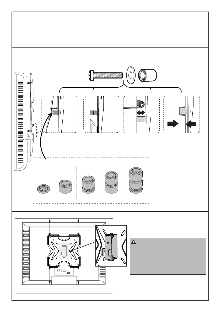
Please Note: When using the spacers it is important to note that they can be used in
multi-layers (meaning stacked). If you have any difficulty understanding how to install
the TV bolts or spacers, please contact our Technical Support line at (877) 419-7832
Bump
See Option C Cables
See Option D Recessed Holes
See Option E
Curved TV
See Option B
Parts Needed if You Have a TV as Shown Below
When attaching the TV Plate to
the back of the TV, ensure the
hooks are pointing to the bottom
of the TV and are equally
centered on the back of
the TV.
Spacers
G1 G2 G2+G2G1+G2 G1+G2+G2
05

Option B (For Curved Back TV)
B1/B2B1/B2
C2/D/E2/F2
Option A (For Flat Back TV)
B1/B2
C1/E1/F1
Spacers must be tall enough so that the curve on the back of the TV will not
interfere with the mounting plate.
G1/G2G1/G2
Phillips Screwdriver
(Not lncluded)
Phillips Screwdriver
(Not lncluded)
8 in (200mm)
4 in (100mm)
8 in (200mm)
3 in (75mm)
4 in (100mm)
6 in (150mm)
6 in (150mm)
3 in (75mm)3 in (75mm) For VESA hole pattern:
3x3 in (75x75 mm)
4x4 in (100x100 mm)
4x8 in (100x200 mm)
6x6 in (150x150 mm)
8x4 in (200x100 mm)
8x8 in (200x200 mm)
Refer back to Spacer Instructions
on Page 05, If needed
06

Option C (For TV with A “Bump”)
B1/B2
C2/D/E2/F2
G1/G2
Spacers must be large enough so TV Plate are flush (NO GAP) on bump.
Option D (for TV with Cable Interference)
For cable interference, use spacers [G1] and [G2] to
create extra space between the TV and TV brackets. Phillips Screwdriver
(Not lncluded)
Phillips Screwdriver
(Not lncluded)
B1/B2
C2/D2/E2/E3
B1/B2
C2/D/E2/F2
N
Refer back to Spacer Instructions
on Page 05, If needed
Refer back to Spacer Instructions
on Page 05, If needed
G1/G2G1/G2
07

Option E (For Recessed Holes )
The spacer need to fill in the recessed holes on the basis of the TV so
that the TV brackets are as close to the TV as possible.
C2/D2/E2
B1/B2
C2/D/E2/F2
B1/B2
G1/G2G1/G2
N
Refer back to Spacer Instructions
on Page 05, If needed
Step 2-1
(W) x4
Foot Pad
(R) x1
Reinforcement
Plate
(Y) x1
Trim Ring
Supplied Parts and Hardware for Step 2
This bolt is shown in
actual size.
(A) x3
M6x25mm
Bolt (P) x1
Support Pillar
(O) x1
Tempered
Glass Base
(V1) x1
5/32 in (4mm)
Small Allen Key
Place foot pads [W] to the painted side of the tempered glass
base [O] in the corners.
Step 2 Assemble the Base
WO
W
08

(X) x2
Safety Strap
Supplied Parts and Hardware for Step 3
This bolt is shown in actual size.
Step 2-2 Connect the support pillar [P] to tempered glass base [O].
O
V1
AR
Table
P
R
OYP
A
V1
When assembling the support pillar
[P], ensure the side of the reinforcing
plate [R] with paper is facing the
glass base [O].
Note: Do Not
overtighten the
bolts [A].
(F) x1
Washer
(H) x1
M8x40mm
Bolt
(V2) x1
13/64 in (5mm)
Large Allen Key
09

Distance from the hooks on the TV
Brackets to the bottom of the TV
Recommended TV Mounting
Plate Location
9 3/4" to 11 1/2"
8" to 9 3/4"
Less Than 8"
Location #1
Location #2
Location #3
Note: Before attaching the TV Mounting
Plate to the pillar, measure the distance
from the upper hook on the TV Bracket
to the bottom of the TV. Then refer to
chart below for the recommended
mounting location. To add an additional
“2” of space between your TV and the
base, use the lower hooks located on the
TV Brackets. We always recommend
using the lowest possible attachment
location for the safest assembly.
Step 3 Connect the TV Plate [M] to Support Pillar [P]
Mounting Location #1
Mounting Location #2
Mounting Location #3
HEAVY! You may
need assistance
with this step.
Location #1Location #1
Location #2Location #2
Location #3Location #3
10

(K) x1
Wire Clip
Supplied Part for Step 4
Step 4 Secure the Wire Clips [K] to Support Pillar [P]
K
Connect TV plate [N] to support
pillar [P] using bolt [H], washer [F],
Allen Key [V2].
F
V2
H
X
11

Secure The Safety Straps With TV Stand Against The Wall
For wood stud installation, follow STEP 5B.
For solid concrete or concrete block installation, follow
STEP 5C.
For wooden table furniture installation, follow STEP 5A.
X
Step 5A
For Wooden Table Furniture Installation
Note: For the safest possible installation, we recommend using the included safety
straps. By doing so, you will greatly reduce the possibility of a TV Tip Over.
● DO NOT USE ANCHOR [Z2] FOR THIS STEP!
Note: It is necessary to predrill a
pilot hole to avoid splitting the
wood. Being careful not to
damage your furniture.
Caution: The mounting surface
must be thicker than 1 in (25mm).
Supplied Hardware for Step 5A
x2
Z1
x4
Z2
x2
Z3
It is reccommended that the
safety straps be mounted at
least 12” apart.
Screw M5X25mmScrew M5X60mm M5 Washer(BK)
For wooden table furniture/wood stud installation.
Pencil
(Not lncluded)
Phillips Screwdriver
(Not lncluded)
1 in (25mm)
1/8 in (3mm)
1 in (25mm)
1/8 in (3mm)
1/8 in (3mm)
1in (25mm)
Z2
X
12

OR
Awl
(Not lncluded)
Stud Finder
(Not lncluded)
Pencil
(Not lncluded)
Step 5B
For Wooden Stud Installation
● DO NOT USE ANCHOR [Z2] FOR THIS STEP!
● Any material covering the wall must not exceed 5/8 in (16 mm).
● Nominal wood stud size: common 2 x 4 in (51 x 102 mm) minimum 1½
x 3½ in (38 x 89 mm).
● Stud center must be verified by using an awl or stud finder.
2 1/2 in (60mm)
1/8 in (3mm)
1/8 in (3mm)
Wood Drill Bit
X
Note: Each strap must be
mounted to a separate stud. Phillips Screwdriver
(Not lncluded)
Z1
Z3
13

Step 5C For Solid Concrete or Concrete Block Installation
● Must use wall anchor [Z4] for this step.
● Any material covering the wall must not exceed 5/8 in (16 mm).
● Minimum solid concrete thickness: 203 mm (8 in).
● Minimum concrete block size: 8 x 8 x 16 in (203 x 203 x 406 mm).
● Never drill into the mortar between blocks.
Wall Anchor 8x50mm
Pencil
(Not lncluded)
Supplied Hardware for Step 5C
x2
Z1
x2
Z3
x2
Z4
Screw M5X60mm M5 Washer(BK)
12 in (305mm)
Z4
5/16 in (8mm)
Concrete Drill Bit
Hammer
(Not lncluded)
Phillips Screwdriver
(Not lncluded)
Z1
Z3
2 9/16 in (65mm)
5/16 in (8mm)
14

Step 6 Swivel Adjustment
If necessary, the TV plate or TV can be swivelled manually.
15

Avant de commencer, vérifions que ce support est parfait pour vous!
CONSIGNES DE SECURITE IMPORTANTES
Attention: évitez les potentiels dommages corporels et aux biens!
• Ne pas utilizer ce produit dans le cas où cet instruction n’a pas indiqué. Ne
pas dépasser le poids limité. Nous ne sommes pas responsables des
dommages causés par le montage incorrect ou l’utilisation inappropriée.
• Veuillez bien lire tous les instructions avant du montage. Si vous ne
comprenez pas les instructions ou avez des questions, veuillez contacter notre
ligne d'assistance technique au (877) 419-7832 ou notre service clientèle à
44 lbs/
19.96 kg
1
Mesurez le modèle VESA de votre téléviseur:
Minimum: 75 x 75mm/3 x 3 pouce (LxH)
Maximum: 200 x 200mm/8 x 8 pouce (LxH)
1
L
H
Béton massif ou
bloc de béton
NE PAS installer dans une cloison sèche seule.
Montants en bois
(avec cloison sèche)
Pour les installations
de sangles de sécurité,
vous devrez vérifier la
construction de votre
mur.
Si ce support TV n'est PAS compatible, veuillez contacter notre ligne d'assistance
technique au (877) 419-7832 ou notre service clientèle à l'adresse
Si votre téléviseur ne se situe pas entre les
mesures minimum et maximum, n'utilisez
pas ce produit.
Si votre téléviseur pèse plus de 44 lb,
n'utilisez pas ce produit.
16

Pièces et matériel fournis
Avertissement: Ce produit contient des petits objets susceptibles de présenter un
risque d'étouffement en cas d'ingestion.
Avant de commencer l'assemblage, vérifiez que toutes les pièces sont incluses et en
bon état. N'utilisez pas de pièces endommagées ou défectueuses. Si vous avez besoin
de pièces de rechange, veuillez contacter notre ligne d'assistance technique au
un support compatible.
• Veuillez noter: le matériel inclus dans cet ensemble ne sera pas utilisé en totalité.
Outils nécessaires (non inclus)
Mètre ruban
Mètre
ruban
5/16 pouce (8mm)
Foret à béton de Marteau-piqueur
Tournevis
cruciform
Ailette
Détecteur de
goujons
Mètre
ruban Crayon 1/8 pouce (3mm)
Mèche à bois
Foreuse Tournevis
cruciform
Tournevis
cruciform
Pour l'installation de sangles de sécurité dans un mur en béton
Pour l'installation d'une sangle de sécurité dans les tables/meubles en bois et les
montants en bois.
Pour le montage du support TV
Pièces et matériel fournis pour l'étape 1
(B1) x4
M4/M5
Rondelles
(B2) x4
M6/M8
Rondelles
(N) x1
Plaque TV
Crayon Foreuse
17

Étape 1 Fixez les Plaque TV [N] sur le TV
Sélectionnez les Boulons de TV.
Une seule taille de boulon convient à votre TV.
(C1) x4
M4x12mm
Boulon
(C2) x4
M4x30mm
Boulon
(D) x4
M5x25mm
Boulon
(E1) x4
M6x15mm
Boulon
(F1) x4
M8x15mm
Boulon
La taille réelle des boulons et des entretoises est indiquée.
(G1) x4
L2.5mm
Entretoises
(G2) x8
L10mm
Entretoises
(F2) x4
M8x35mm
Boulon
Longueur de la vis: vérifiez que le filetage est correctement engagé avec les boulons
ou la combinaison vis/entretoises. Nous recommandons un engagement du filetage
sur au moins 5 tours.
- Trop court, le TV ne sera pas maintenu.
- Trop long, le TV sera endommagé.
Trop court Correct Trop long
(E2) x4
M6x35mm
Boulon
OU OU OU
M6M5 M8M4
18

Veuillez noter: lors de l'utilisation des entretoises, il est important de noter qu'elles
peuvent être utilisées sur plusieurs couches (c'est-à-dire empilées). Si vous rencontrez
des difficultés pour comprendre comment installer les boulons ou les entretoises du TV,
veuillez contacter notre service d'assistance technique au (877) 419-7832 ou notre
Bosse Voir
option C Câbles Voir
Option D Trous encastrés
Voir Option E
TV incurvée
Voir option B
Les pièces nécessaires si vous avez un TV tel qu'indiqué
ci-après
Lorsque vous fixez la façade à
l'arrière du TV, assurez-vous que
les crochets orientés vers le bas
sont dirigés vers le bas du TV et
que la façade est également
centrée sur l'arrière du TV.
Entretoises
G1 G2 G2+G2G1+G2 G1+G2+G2
19

Option B (pour les TV à dos incurvé)
B1/B2B1/B2
C2/D/E2/F2
Option A (pour les TV à dos plat)
B1/B2
C1/E1/F1
La hauteur des entretoises doit être suffisante pour éviter que la courbe à
l'arrière du TV n'interfère avec la plaque de montage.
La hauteur des entretoises doit être suffisante pour éviter que la courbe à
l'arrière du TV n'interfère avec la plaque de montage.
G1/G2G1/G2
Tournevis cruciform
(non inclus)
Tournevis cruciform
(non inclus)
8 pouce (200mm)
4 pouce (100mm)
8 pouce (200mm)
3 pouce (75mm)
4 pouce (100mm)
6 pouce (150mm)
6 pouce (150mm)
3 pouce (75mm)3 pouce (75mm) Pour le modèle de trou VESA:
3x3 pouce (75x75 mm)
4x4 pouce (100x100 mm)
4x8 pouce (100x200 mm)
6x6 pouce (150x150 mm)
8x4 pouce (200x100 mm)
8x8 pouce (200x200 mm)
Reportez-vous aux instructions
relatives aux entretoises à la
page 19, si nécessaire
20
Table of contents
Languages:
Other ErgoAV TV Mount manuals

ErgoAV
ErgoAV ERDHM2-01B User manual

ErgoAV
ErgoAV ERMMS1 -01 B User manual

ErgoAV
ErgoAV ERMTM2-01B User manual

ErgoAV
ErgoAV ERMTS1-01B User manual

ErgoAV
ErgoAV ERMTL1-01B User manual

ErgoAV
ErgoAV ERMCM1-01B User manual

ErgoAV
ErgoAV ERMTM1-01B User manual

ErgoAV
ErgoAV ERMTM2-01B User manual

ErgoAV
ErgoAV ERTSM2-01B User manual

ErgoAV
ErgoAV ERDHM1-01B User manual