ErgoAV ERMTM2-01B User manual
1 2 3 4
2 431
D
E
C
B
A
F
E
D
C
B
A
(.XXX)
##
.XXX
##
ERMTM2-01B-Manual
(英法西)-JY
0-30 ±1
30-150 ±2
150-300 ±3
300-450 ±4
>450 ±5
00
860-00055-00
1 1
技术要求:
1、材质:封页105g 铜板纸;内页80g双胶纸
2、展开尺寸:A4,如图所示装订成型为A5,P44
3、颜色:单色
4、印刷:印刷图档见后续页,双面印刷
5、装订方式:骑马钉
Ella
2022/02/17
刀模线:
内折线:
注:此页为技术说明,非印刷内容
297mm
210mm
装订效果图:
展开尺寸图:
深圳市倍思奇
创新科技有限公司
封
面
封
底

TV Mount Instruction Manual (A)
Model: ERMTM2-01B
THANK YOU FOR CHOOSING THIS ERGOAV PRODUCT!
At ErgoAV, we want to add value to your AV experience by providing the highest
quality products and services in the industry. If you have any concerns or
comments, please contact us.
ErgoAV Customer Care
Phone (877) 419-7832 M-F 8am to 8pm CST
email: [email protected]
website: www.ergoav.com
address: 9501 Louisiana Ave N, #200 Brooklyn Park, MN 55445
English pages 02-14 French pages 15-27 Spanish pages 28-40
75 mm ≈ 3 in
100 mm ≈ 4 in
200 mm ≈ 7 7/8 in
300 mm ≈ 11 13/16 in
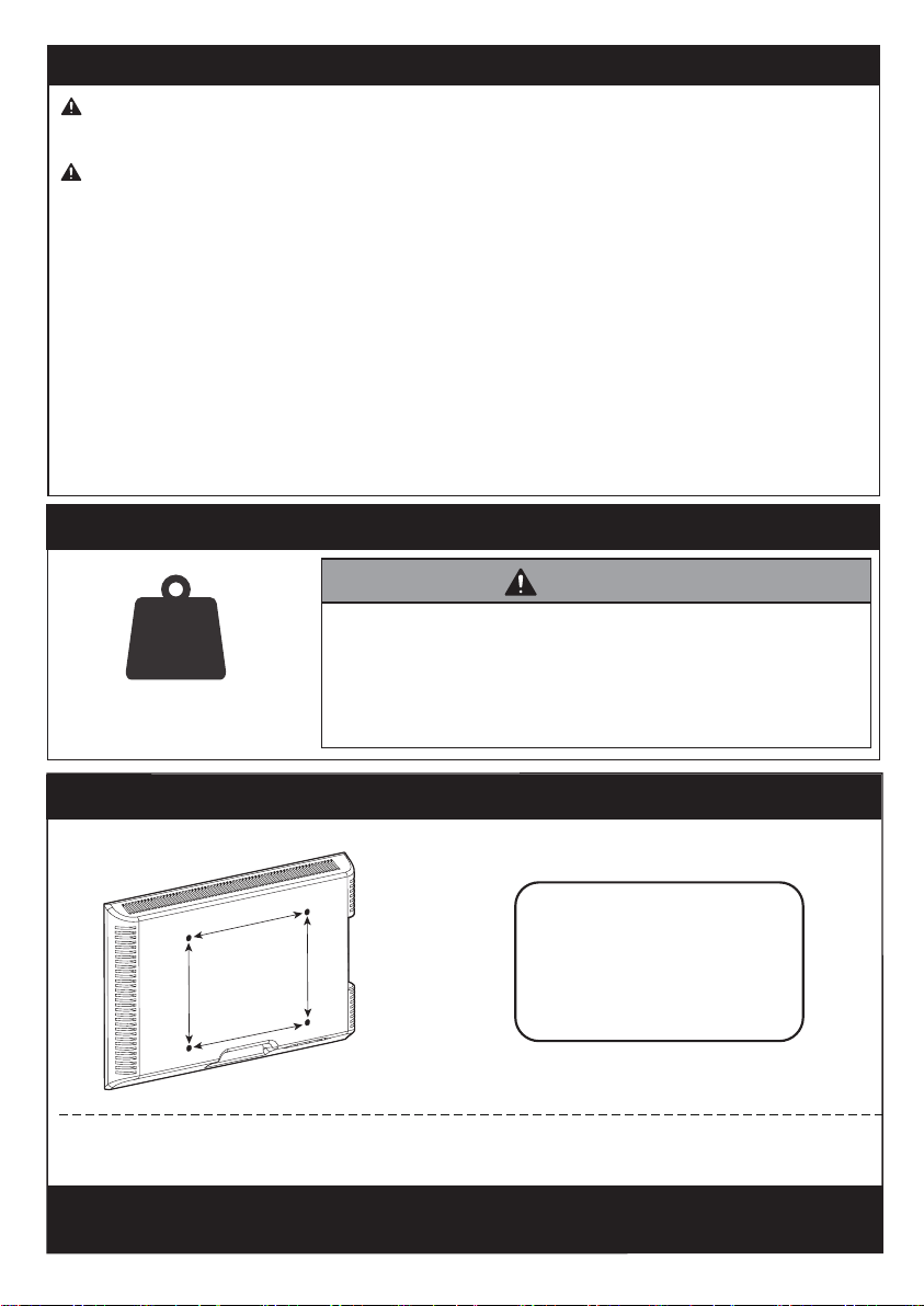
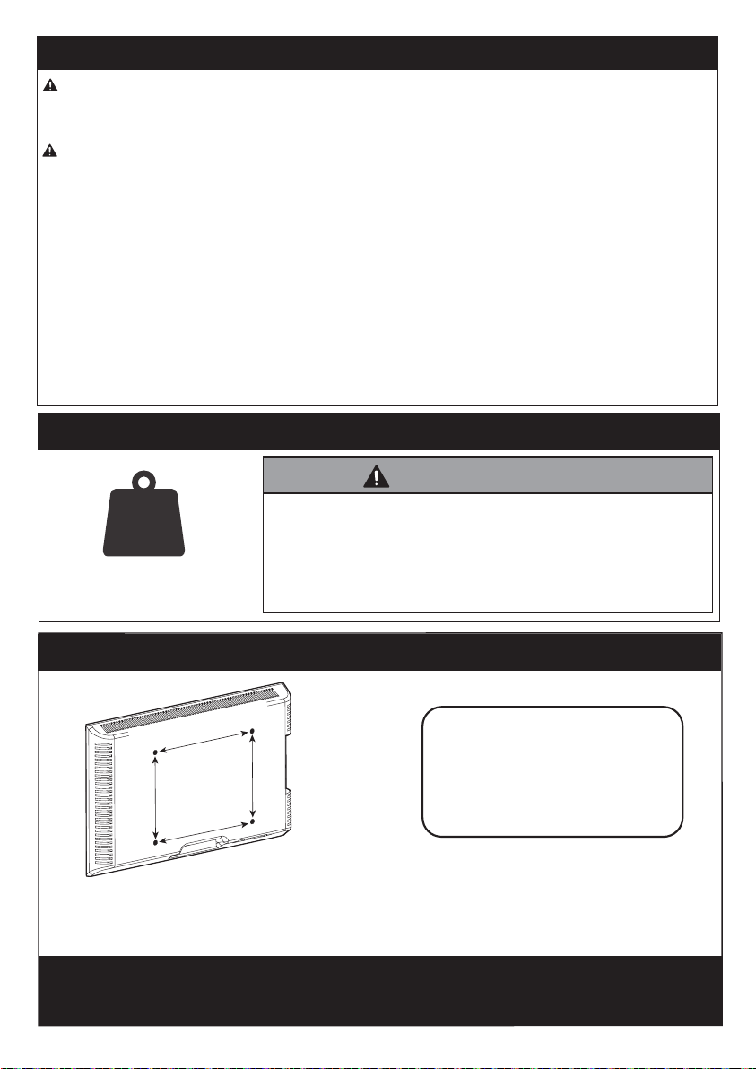
Minimum VESA pattern: 75mm/3 in (W)x75mm/3 in (H)
If your TV VESA is greater than 400x300 mm/16x11.8 in or less than
VESA 75x75mm/3x3 in , this mount is NOT compatible.
MAX: 400mm/16 in
MAX: 300mm/11.8 in
DANGER!Please carefully read all instructions before attempting installation. If you do
not understand the instructions or have any concerns or questions, please contact our
CAUTION: Use with products heavier than the maximum weights indicated may result in
instability causing possible injury.
• Do not use this product for any purpose that is not explicitly specified in this manual. Do
not exceed weight capacity. We are not liable for damage or injury caused by improper
mounting, incorrect assembly or inappropriate use.
• This product is designed for use in wood stud, and solid concrete walls. -
DO NOT install
into drywall alone.
• The wall must be capable of supporting four times the weight of the TV and mount
combined.
• Use this mounting system only for its intended use as described in these instructions. Do
not use attachments not recommended by the manufacturer.
• Do not use outdoors.
• Route cords and cables properly to avoid mechanical damage.
• SAVE THESE INSTRUCTIONS
If this mount is NOT compatible, please contact our Technical Support line at
(877) 419-7832 or customer service at [email protected] to find a compatible mount.
DO NOT exceed the maximum weight indicated. This mounting
system is intended for use only within the maximum weights
indicated. Use with products heavier than the maximum weights
indicated may result in failure of the mount and its accessories,
causing damage and or injury.
If your TV weighs more,
do not use this product.
99lbs/
44.9kg
WARNING
Weight Restrictions
IMPORTANT SAFETY INFORMATION
Check the VESA Pattern of Your TV before the Installation
400 mm ≈ 15 3/4 in
02 03 04 05 06 07 08 09 10 11 12 13 14
15 16 17 18 19 20 21 22 23 24 25 26 27
28 29 30 31 32 33 34 35 36 37 38 39 40
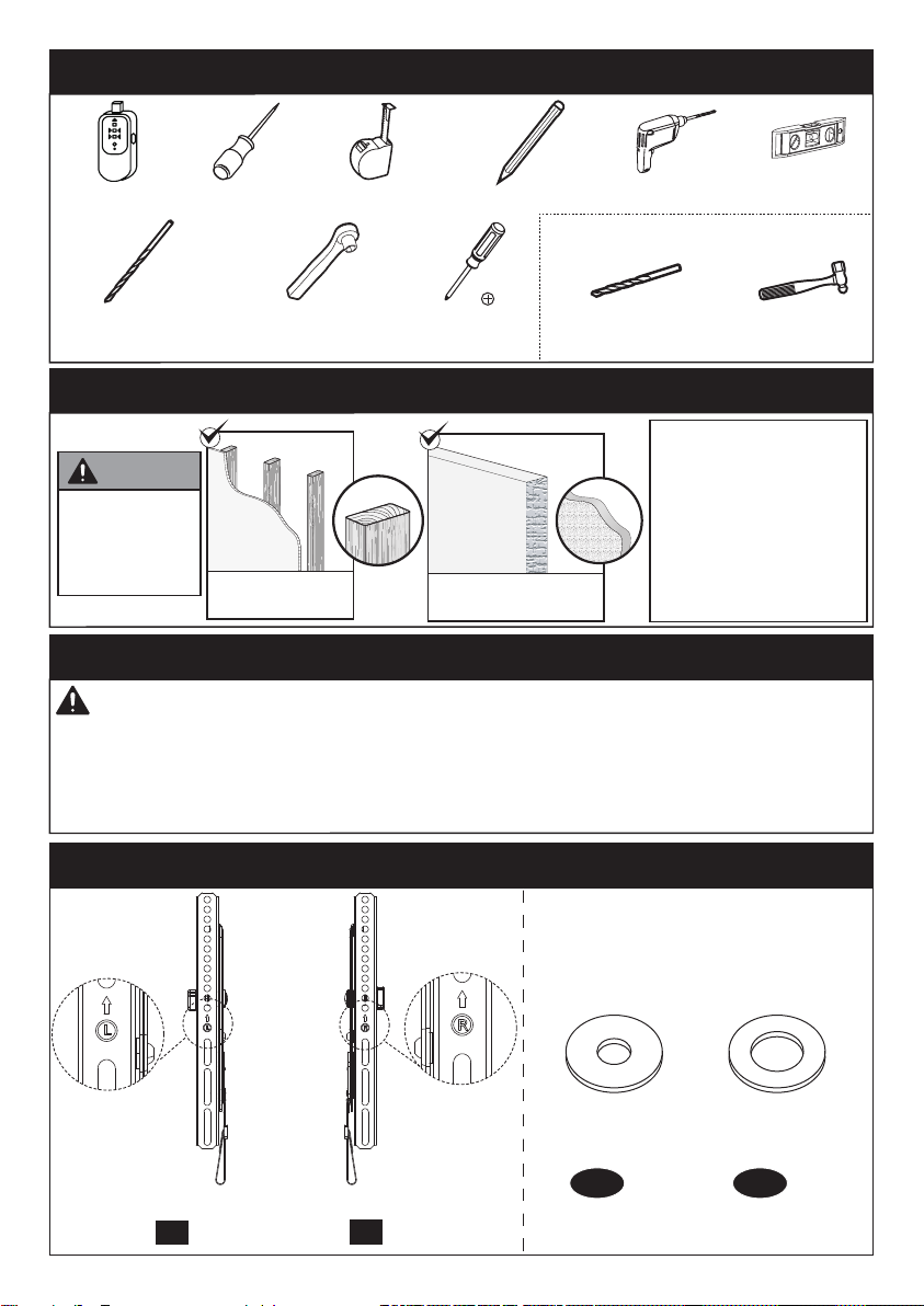
Supplied Parts and Hardware for Step 1
Verify Your Wall Construction
If you are not sure of
the wall construction,
please contact our
Technical Support line
at (877) 419-7832 or
customer service at
Supplied Parts and Hardware
Solid Concrete
Wall
CAUTION
DO NOT
install into
drywall alone Wood Studs
(with Drywall)
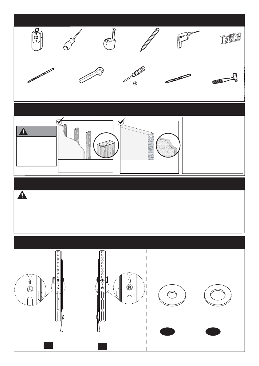
Left TV Bracket
x1
02
Right TV Bracket
x1
03
Tools Needed (Not lncluded)
Stud Finder Tape Measure Pencil Electric Drill Level
7/32 in (5.5mm)
Wood Drill
1/2 in (13mm)
Socket Wrench
Phillips
Screwdriver
3/8 in (10mm)
Concrete Drill Hammer
Awl
Washers
x4
B1
x4
B2
M4/M5 M6/M8
WARNING: This product contains small items that could be a choking hazard if swallowed.
Before starting assembly, verify all parts are included and undamaged. Do not use
damaged or defective parts. lf you require replacement parts, please contact our
• Please note: Not all hardware included in this package will be used.
(Needed for concrete installs)
02 03 04 05 06 07 08 09 10 11 12 13 14
15 16 17 18 19 20 21 22 23 24 25 26 27
28 29 30 31 32 33 34 35 36 37 38 39 40

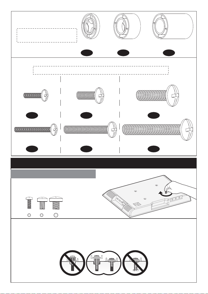
Only one bolt size fits your TV.
Step 1 Secure the TV Brackets to the TV
Select TV Bolts
M4 M6 M8
M4x12mm
M8M4 M6
NOTE: The bolts are shown in actual size
M6x15mm M8x25mm
TV Bolts (Only one bolt size fits your TV)
NOTE: The spacers are
shown in actual size
Spacers
L2.5mm
x8
F1
x4
F2
x4
F3
x4
C1
x4
D1
x4
E1
M4x30mm M6x35mm M8x50mm
x4
C2
x4
D2
x4
E2
L10mm L22mm
Bolt length: Verify adequate thread engagement with bolts or bolts/spacers
combination. We recommend thread engagement by at least 5 turns.
-Too short will not hold the TV.
-Too long will damage the TV.
Note: Please do not over tighten the TV bolts to avoid damaging your TV.
Too short Correct Too long
OR OR
02 03 04 05 06 07 08 09 10 11 12 13 14
15 16 17 18 19 20 21 22 23 24 25 26 27
28 29 30 31 32 33 34 35 36 37 38 39 40
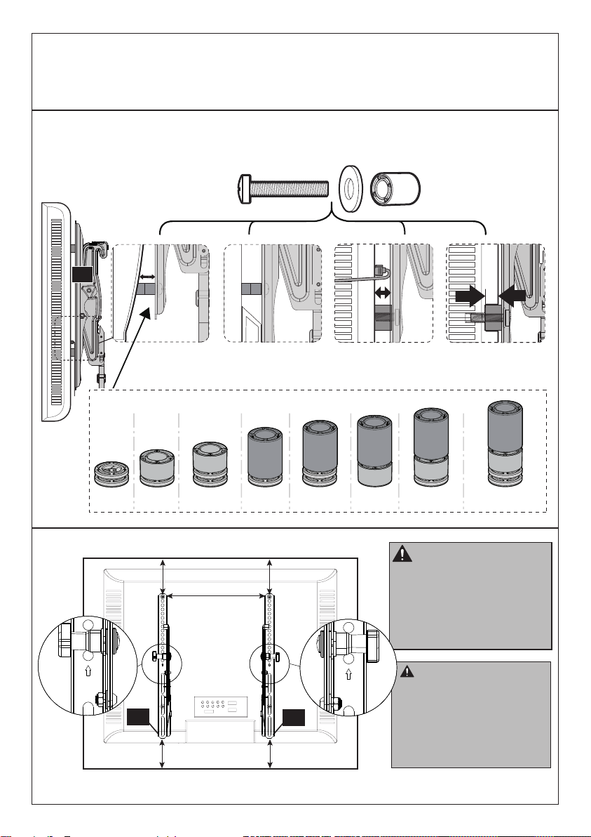
PLEASE NOTE: When using the spacers it is important to note that they can be used
in multi-layers (meaning stacked). If you have any difficulty understanding how to
install the TV bolts or spacers, please contact our Technical Support line at
Bump
See Option C Cables
See Option D Recessed Holes
See Option E
Parts Needed if You Have a TV as Shown Below
Curved TV
See Option B
03
Spacers
F1+F1 F1+F2 F1+F3F1+F1+F2 F1+F1+F3 F2+F3 F1+F2+F3 F1+F1+F2+F3
CAUTION: When attach-
ing the TV brackets to the
back of the TV, ensure the
Up Arrows are pointing to the
top of the TV and are equally
centered on the back of the
TV.
PLEASE NOTE: The bolt
hole locations on your TV
may vary in accordance of
the manufacturers design
of the TV. We are only
illustrating possible
locations of the bolt holes.
03 02
02 03 04 05 06 07 08 09 10 11 12 13 14
15 16 17 18 19 20 21 22 23 24 25 26 27
28 29 30 31 32 33 34 35 36 37 38 39 40
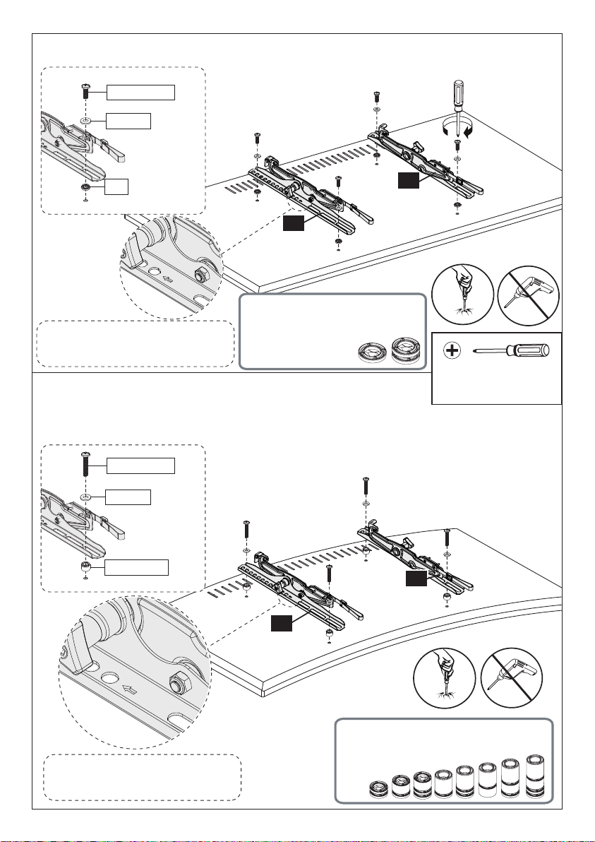
Option A (For Flat Back TV)
D
o
n
o
t
o
v
e
r
-
t
i
g
h
t
e
n
02
02
03
03
C1/D1/E1
B1/B2
F1
(If needed)
C2/D2/E2
B1/B2
F1/F2/F3
Phillips Screwdriver
(Not lncluded)
Option B (For Round Back TV)
D
o
n
o
t
o
v
e
r
-
t
i
g
h
t
e
n
Spacers must be tall enough so that the curve on the back of the TV will not interfere
with the mounting plate.
Refer back to spacer instruc-
tions on page 5, if needed
NOTE: The UP arrow should
point towards the top of TV.
NOTE: The UP arrow should
point towards the top of TV.
Refer back to spacer instructions
on page 5, if needed
02 03 04 05 06 07 08 09 10 11 12 13 14
15 16 17 18 19 20 21 22 23 24 25 26 27
28 29 30 31 32 33 34 35 36 37 38 39 40
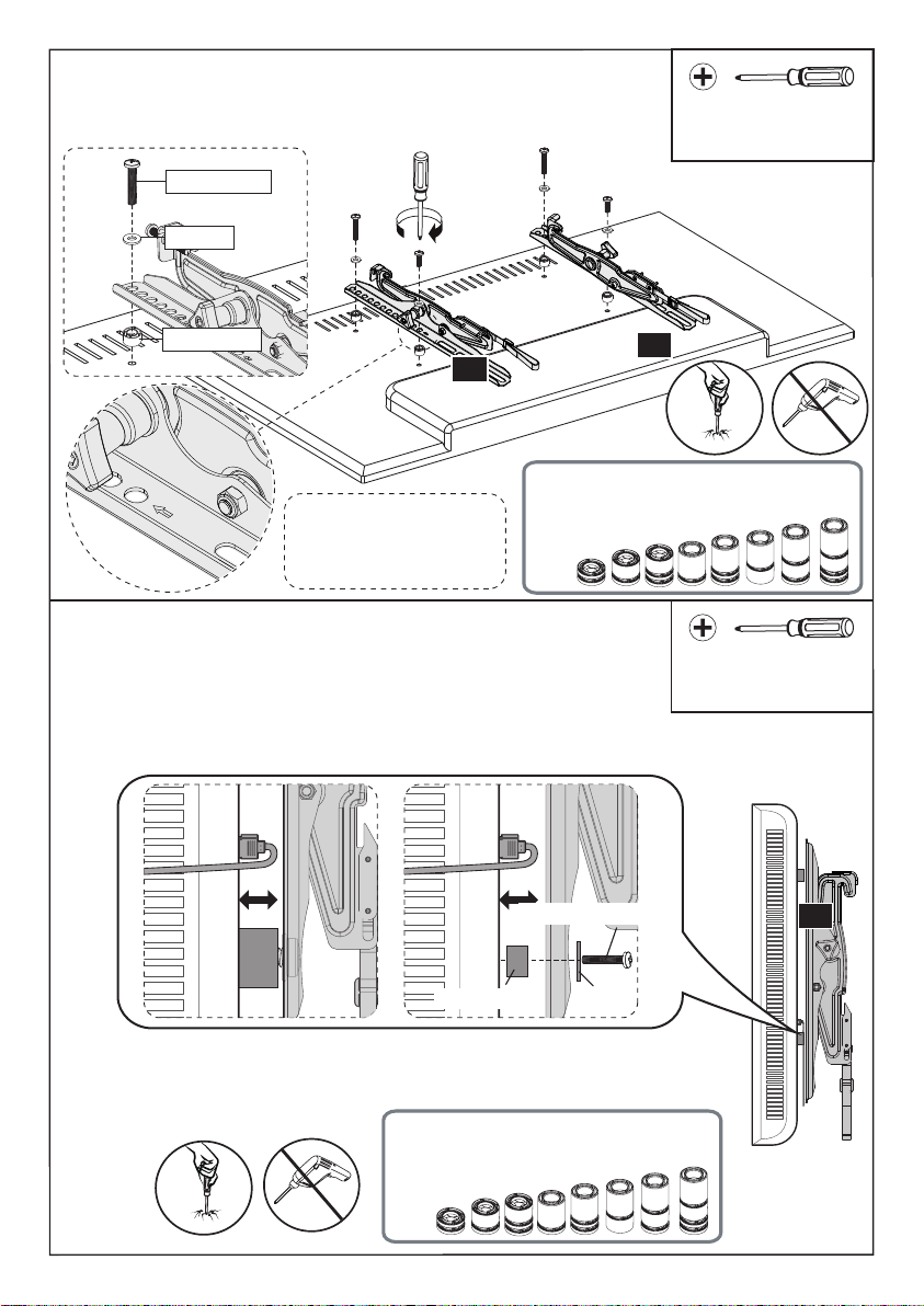
Option C (For TV with A “Bump”)
D
o
n
o
t
o
v
e
r
-
t
i
g
h
t
e
n
02
03
C2/D2/E2
B1/B2
F1/F2/F3
Spacers must be tall enough so there is no gap between
TV braceket and bump on the back of the TV. Phillips Screwdriver
(Not lncluded)
D
o
n
o
t
o
v
e
r
-
t
i
g
h
t
e
n
Option D (For TV with Cable Interference)
03
Phillips Screwdriver
(Not lncluded)
For cable interference, use spacers [F1], [F2] and [F3] to
create extra space between the TV and TV brackets.
F1/F2/F3 B1/B2
C2/D2/E2
NOTE: The UP arrow
should point towards
the top of TV.
Refer back to spacer instructions
on page 5, if needed
Refer back to spacer instructions
on page 5, if needed
02 03 04 05 06 07 08 09 10 11 12 13 14
15 16 17 18 19 20 21 22 23 24 25 26 27
28 29 30 31 32 33 34 35 36 37 38 39 40

x4
Wall
Anchor
10X60mm
This anchor is for concrete
walls ONLY. DO NOT use
them in drywall or wood
studs.
CAUTION!
x4 Lag Screw
5/16 X 2 3/4 in
Supplied Parts and Hardware for Step 2
Wall Plate x1
01
Wall Plate Template x1
04
A1
A2
Note: The lag screw is shown in actual size
D
o
n
o
t
o
v
e
r
-
t
i
g
h
t
e
n
Option E (For TV with Recessed Holes)
Phillips Screwdriver
(Not lncluded)
Refer back to spacer instructions
on page 5, if needed
The spacer need to fill in the recessed holes on the basis
of the TV so that the TV brackets are as close to the TV
as possible.
03
B1/B2
F1/F2/F3
C2/D2/E2
02 03 04 05 06 07 08 09 10 11 12 13 14
15 16 17 18 19 20 21 22 23 24 25 26 27
28 29 30 31 32 33 34 35 36 37 38 39 40
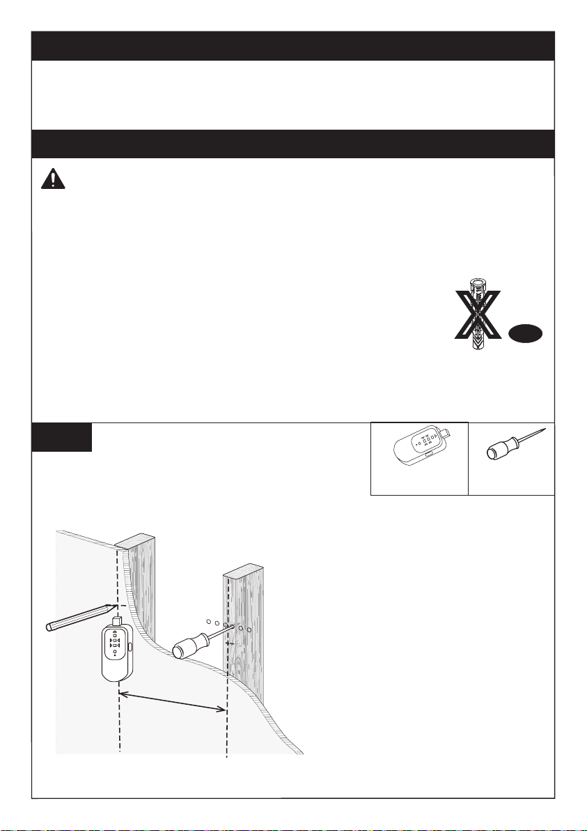
16 in (406mm)
OR
2A-1
Use a stud finder (not included) to
locate wood studs or use an awl
(not included) to verify the edges.
Mark the edge and center locations.
Step 2A Wood Stud Option
WARNING:
Step 2 Attach the Wall Plate [01] to the Wall
For wood stud installation, follow STEP 2A.
For concrete installation, follow STEP 2B.
Wall
Anchor
X
A2
Ensure the wall plate is securely fastened to the wall before
continuing to the next step.
Do not use a drill for tightening the lag screws! Only use a socket wrench.
● Nominal wood stud size: common 2 x 4 in (51 x 102 mm)
● Stud center must be verified.
Avoid potential personal injury or property damage! DO NOT over-tighten the lag
screws [A1]. Tighten the lag screws [A1] only until they are pulled firmly against
the wall plate [01].
DO NOT USE ANCHOR [A2] FOR THIS STEP.
Awl
(Not lncluded)
Stud finder
(Not lncluded)
02 03 04 05 06 07 08 09 10 11 12 13 14
15 16 17 18 19 20 21 22 23 24 25 26 27
28 29 30 31 32 33 34 35 36 37 38 39 40
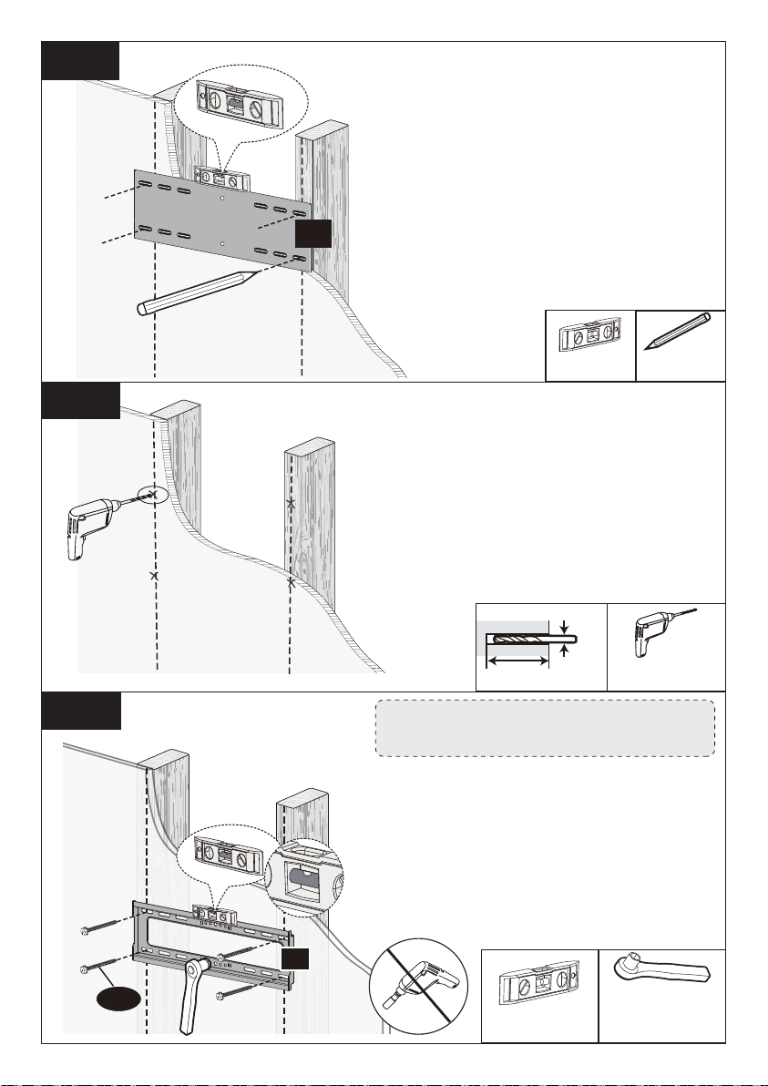
04
Install the wall plate using lag
screws [A1]. Tighten the lag
screws [A1] is pulled firmly
against the wall plate. DO NOT
over-tighten the lag screws
[A1].
2A-4 Note: Do not use a drill to tighten the
lag screws. Only use a socket wrench.
A1
01
2A-2
2A-3
Drill pilot holes using a 7/32 in
(5.5mm) diameter drill bit. Make
sure the depth is not less than
2 3/4 in (70mm).
1/2 in (13mm)
Socket Wrench
(Not Included)
Level
(Not Included)
Pencil
(Not Included)
Electric drill
(Not Included)
2 3/4 in (70mm)
7/32 in
(5.5 mm)
Level
(Not Included)
Position the wall plate template [04]
at your desired height and line up
the holes with your stud center line.
Level the wall plate template [04]
and mark the holes.
02 03 04 05 06 07 08 09 10 11 12 13 14
15 16 17 18 19 20 21 22 23 24 25 26 27
28 29 30 31 32 33 34 35 36 37 38 39 40

3/8 in (10mm)
3 in (75mm)
Drill 4 pilot holes using a 3/8
in (10mm) diameter drill bit.
Make sure the depth is not
less than 3 in (75mm).
Step 2B Solid Concrete Wall Option
Wall
Anchor
A2
2B-1
2B-2
01
WARNING:
Wall Thickness
≥5.5 in
(140mm)
04
● Mount the wall plate directly onto the concrete surface without
any covering.
● The thickness of the concrete wall must exceed 5.5 in (140 mm).
●Avoid potential personal injury or property damage! DO NOT over-tighten the lag
screws [A1]. Tighten the lag screws [A1] is pulled firmly against the wall plate.
●Ensure the wall plate is securely fastened to the wall before continu-
ing to the next step.
Do not use a drill for tightening the lag screws! Only use a socket wrench.
Position the wall plate
template [04] at your desired
height. Level the wall plate tem-
plate [04] and mark the pilot hole
locations.
Electric Drill
(Not Included)
Pencil
(Not Included)
Level
(Not Included)
02 03 04 05 06 07 08 09 10 11 12 13 14
15 16 17 18 19 20 21 22 23 24 25 26 27
28 29 30 31 32 33 34 35 36 37 38 39 40
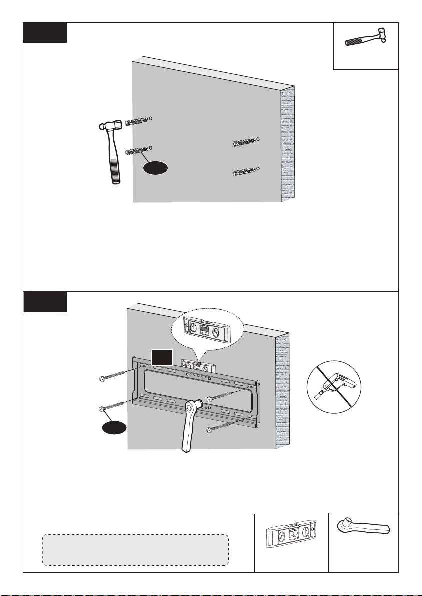
Install the wall plate [01] using lag screws [A1]. Tighten the lag
screws [A1] is pulled firmly against the wall plate [01]. DO NOT
over-tighten the lag screws [A1].
2B-4
1/2 in (13mm)
Socket Wrench
(Not Included)
2B-3
Use the hammer to knock anchors [A2] into the wall. Be sure
the anchors [A2] are seated flush with the concrete surface.
A1
A2
Note: Do not use a drill to tighten the
lag screws. Only use a socket wrench.
Hammer
(Not Included)
Level
(Not Included)
01
02 03 04 05 06 07 08 09 10 11 12 13 14
15 16 17 18 19 20 21 22 23 24 25 26 27
28 29 30 31 32 33 34 35 36 37 38 39 40
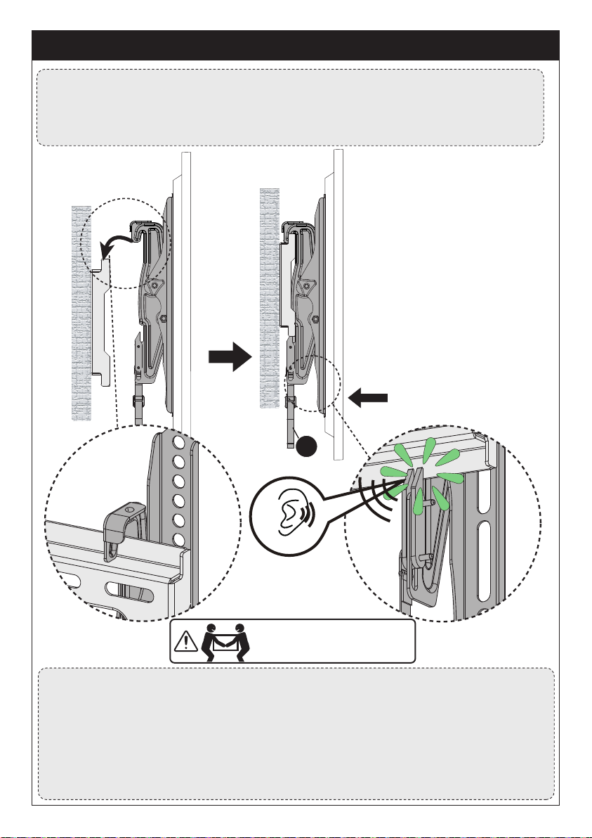
②
Gently Push
Step 3 Secure the TV onto the Wall Plate
HEAVY! You may need
assistance with this step.
①
To Hang TV onto the Wall Plate
1. Hang the TV with brackets [02] and [03] onto the wall plate [01].
2. Gently press the bottom of the TV towards the wall until you hear the safety locks
“click” into place on both sides of the mount.
②
Locking
R
Caution: to avoid potential injury and person property damage, two people should
assist in removing the TV from the mount.
1. Verify that all cables are disconnected from the back of the TV and the TV is
unplugged from wall.
2. While gently applying pressure to the front of the TV towards the wall, pull down on
the safety straps until they are full disengaged.
3. While keeping the straps in the disengaged position, move the bottom of the TV
away from the wall and lift the TV off the wall plate.
①
02 03 04 05 06 07 08 09 10 11 12 13 14
15 16 17 18 19 20 21 22 23 24 25 26 27
28 29 30 31 32 33 34 35 36 37 38 39 40

Step 4 Adjustment
Please do not over-tighten
or over-loosen the knobs.
CAUTION!
Tilt Adjustment
Supplied Hardware for Step 4
x1
3/16 in (5mm)
Allen Key
3/16 in (5mm)
Allen Key
K
1. Use tension knobs on the sides of the TV Brackets to allow adjustment of
the TV to desired position.
2. After making any adjustments, always re-tighten the tension knobs to
hold TV in place and avoid unwanted movement.
02 03 04 05 06 07 08 09 10 11 12 13 14
15 16 17 18 19 20 21 22 23 24 25 26 27
28 29 30 31 32 33 34 35 36 37 38 39 40
75 mm ≈ 3 pouce
100 mm ≈ 4 pouce
200 mm ≈ 7 7/8 pouce
300 mm ≈ 11 13/16 pouce
Maximum
: 300mm/
11.8
pouce
NE PAS dépasser le poids maximum indiqué. Ce support TV
est destinée à être utilisé uniquement dans la limite des
poids maximums indiqués. L'utilisation de produits plus
lourds que les poids maximums indiqués peuvent entraîner
une défaillance du support TV et de ses accessoires, et
provoquer des dommages et/ou des blessures.
Si votre téléviseur pèse
plus lourd, n'utilisez pas ce
produit.
99lbs/
44.9kg
AVERTISSEMENT
DANGER! Veuillez lire attentivement toutes les instructions avant de tenter l'installation. Si
les instructions ne vous semblent pas claires ou si vous avez des questions, veuillez contacter
notre service d'assistance technique au (877) 419-7832 ou notre service clientèle à l'adresse
ATTENTION: L'utilisation avec des produits plus lourds que les poids maximums indiqués
peut entraîner une instabilité et des blessures possibles.
• N'utilisez pas ce produit à des fins qui ne sont pas explicitement spécifiées dans ce manuel.
Ne dépassez pas la capacité de charge. Nous ne sommes pas responsables des dommages
ou blessures causés par un montage incorrect, un assemblage incorrect ou une utilisation
inappropriée.
• Ce produit est conçu pour être utilisé dans les murs à ossature de bois et les murs en béton
massif. - NE PAS installer dans une cloison sèche seule
• Le mur doit être capable de supporter quatre fois le poids du téléviseur et du support
combinés.
• Utilisez ce système de montage uniquement pour l'usage auquel il est destiné, tel que décrit
dans ces instructions. N'utilisez pas d'accessoires non recommandés par le fabricant.
• Ne pas utiliser à l'extérieur.
• Acheminez correctement les cordons et les câbles pour éviter tout dommage mécanique.
• SAUVEGARDER CES INSTRUCTIONS
Consignes de sécurité importantes
Restrictions de poids
Vérifiez le modèle VESA du TV avant l'installation
400 mm ≈ 15 3/4 pouce
Maximum: 400mm/
16 pouce
Gabarit VESA minimal: 75mmx75mm/3 poucex3 pouce
Si ce support n'est PAS compatible, veuillez contacter notre ligne d'assistance
technique au (877) 419-7832 ou notre service clientèle à l'adresse
Si le gabarit VESA de votre téléviseur mesure plus de 400x300 mm/16x11.8 pouce ou
moins de 75x75 mm/3x3 pouce, ce support de téléviseur N'EST PAS compatible.
02 03 04 05 06 07 08 09 10 11 12 13 14
15 16 17 18 19 20 21 22 23 24 25 26 27
28 29 30 31 32 33 34 35 36 37 38 39 40
Pièces et matériel fournis pour l'étape 1
Vérifiez la construction de vos murs
Support TV droit
x1
02
Support TV gauche
x1
03
Outils nécessaires (non inclus)
Rondelle
x4
B1
x4
B2
M4/M5 M6/M8
Détecteur
de goujons
Mètre ruban Crayon Foreuse Niveau
7/32 pouce (5.5mm)
Foret à bois
1/2 pouce (13mm)
Clé à douille
Tournevis
Phillips
3/8 pouce (10mm)
Foret à béton
Marteau-pi-
queur
Ailette
(Nécessaire pour les installations en
béton)
Si vous n'êtes pas sûr
de la construction du
mur, veuillez contacter
notre ligne d'assis-
tance technique au
(877) 419-7832 ou
notre service clientèle
à l'adresse
CAUTION
NE PAS
installer dans
une cloison
sèche seule Montants en bois
(avec cloison sèche)
Pièces et matériel fournis
AVERTISSEMENT
: Ce produit contient des petits objets susceptibles de présenter un risque d'étouffe-
ment en cas d'ingestion.
Avant de commencer l'assemblage, vérifiez que toutes les pièces sont incluses et en bon état.
N'utilisez pas de pièces endommagées ou défectueuses. Si vous avez besoin de pièces de
rechange, veuillez contacter notre ligne d'assistance technique au
(877) 419-7832 ou notre service clientèle à l'adresse [email protected].
• Veuillez noter : le matériel inclus dans cet ensemble ne sera pas utilisé en totalité.
02 03 04 05 06 07 08 09 10 11 12 13 14
15 16 17 18 19 20 21 22 23 24 25 26 27
28 29 30 31 32 33 34 35 36 37 38 39 40
Mur en béton massif
M4x12mm
M8M4 M6
M6x15mm M8x25mm
Remarque: Les entretoises
sont présentées en taille réelle.
Entretoises
L2.5mm
x8
F1
x4
F2
x4
F3
x4
C1
x4
D1
x4
E1
M4x30mm M6x35mm M8x50mm
x4
C2
x4
D2
x4
E2
L10mm L22mm
[Une seule taille de boulon convient à votre téléviseur]
Boulons de téléviseur
Remarque: Les boulons sont représentés en taille réelle
Longueur de la boulon : Vérifiez que le filetage est correctement engagé avec
les boulons ou la combinaison boulons/entretoises. Nous recommandons un
engagement du filetage sur au moins 5 tours.
- Trop court, le téléviseur ne sera pas maintenu.
- Trop long, le téléviseur sera endommagé.
Remarque : Ne serrez pas trop les boulons de téléviseur pour ne pas l'en-
dommager.
Une seule taille de boulon convient à votre
téléviseur.
Étape 1 Fixez les supports du téléviseur sur le téléviseur
Sélectionnez les boulons TV
M6 M8M4
Trop court
Correct
Trop long
OU OU
02 03 04 05 06 07 08 09 10 11 12 13 14
15 16 17 18 19 20 21 22 23 24 25 26 27
28 29 30 31 32 33 34 35 36 37 38 39 40

Les pièces nécessaires si vous avez un téléviseur tel qu'in-
diqué ci-après
03
Entretoises
F1+F1 F1+F2 F1+F3F1+F1+F2 F1+F1+F3 F2+F3 F1+F2+F3 F1+F1+F2+F3
03 02
Veuillez noter: Lors de l'utilisation des entretoises, il est important de noter qu'elles
peuvent être utilisées sur plusieurs couches (c'est-à-dire empilées). Si vous rencontrez
des difficultés pour comprendre comment installer les boulons ou les entretoises du
téléviseur, veuillez contacter notre service d'assistance technique au (877) 419-7832
ou notre service clientèle à l'adresse [email protected].
Bump
Voir option C Câbles
Voir option D Trous encastrés
Voir option E
Téléviseur
incurvée
Voir option B
ATTENTION: Lorsque vous
fixez les supports TV à
l'arrière du téléviseur,
assurez-vous que les flèches
vers le haut sont dirigées vers
le haut du téléviseur et qu'elles
sont également centrées sur
l'arrière du téléviseur.
EUILLEZ NOTER: Les
emplacements des trous de
boulon sur votre téléviseur
peuvent varier en fonction du
design du fabricant du
téléviseur. Nous représentons
seulement les emplacements
possibles des trous des boulon.
02 03 04 05 06 07 08 09 10 11 12 13 14
15 16 17 18 19 20 21 22 23 24 25 26 27
28 29 30 31 32 33 34 35 36 37 38 39 40

Option A (pour un téléviseur à dos plat)
02
02
03
03
C1/D1/E1
B1/B2
F1
(Au besoin)
C2/D2/E2
B1/B2
F1/F2/F3
Tournevis Phillips
(Non inclus)
Option B (pour un téléviseur à dos arrondi)
La hauteur des entretoises doit être suffisante pour éviter que la courbe à l'arrière du
téléviseur n'interfère avec la plaque de montage.
Reportez-vous aux instruc-
tions d'entretoise de la page
18, si nécessaire.
Reportez-vous aux instructions
d'entretoise de la page 18, si
nécessaire.
REMARQUE : La flèche vers le
haut doit être dirigée vers le
haut du téléviseur.
N
e
p
a
s
t
r
o
p
s
e
r
r
e
r
N
e
p
a
s
t
r
o
p
s
e
r
r
e
r
REMARQUE : La flèche vers le
haut doit être dirigée vers le
haut du téléviseur.
02 03 04 05 06 07 08 09 10 11 12 13 14
15 16 17 18 19 20 21 22 23 24 25 26 27
28 29 30 31 32 33 34 35 36 37 38 39 40
Other manuals for ERMTM2-01B
1
Table of contents
Languages:
Other ErgoAV TV Mount manuals

ErgoAV
ErgoAV ERTSM2-01B User manual

ErgoAV
ErgoAV ERMTL1-01B User manual

ErgoAV
ErgoAV ERDHM1-01B User manual

ErgoAV
ErgoAV ERMCM1-01B User manual

ErgoAV
ErgoAV ERDHM2-01B User manual

ErgoAV
ErgoAV ERMTM1-01B User manual

ErgoAV
ErgoAV ERTSS2-01B User manual

ErgoAV
ErgoAV ERMMS1 -01 B User manual

ErgoAV
ErgoAV ERMTM2-01B User manual

ErgoAV
ErgoAV ERMTS1-01B User manual


