ErgoAV ERMCM1-01B User manual

(A)
Ceiling TV Mount Instruction Manual
Thank You for Choosing this ErgoAV Product!
At ErgoAV, we want to add value to your AV experience by providing the
highest quality products and services in the industry. If you have any
concerns or comments, please contact us.
ErgoAV Customer Care
Phone: (877) 419-7832
Email: [email protected]
Website: www.ergoav.com
Address: 9501 Louisiana Ave N, #200, Brooklyn Park, MN 55445
Model: ERMCM1-01B
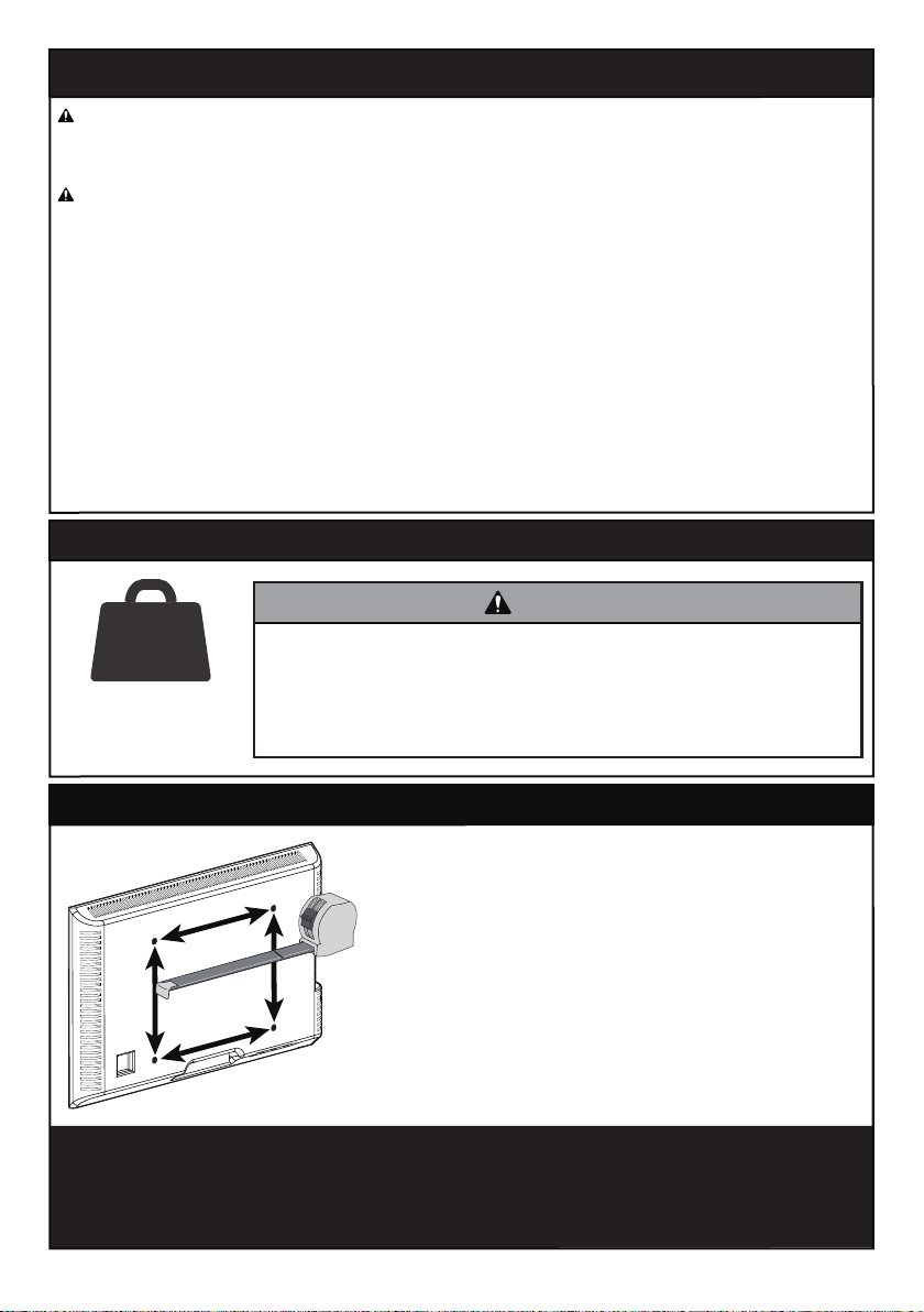
Check the VESA Pattern of Your TV before You Begin the Installation
IMPORTANT SAFETY INFORMATION
If your TV's VESA Pattern is smaller than 100mm x 100mm / 3.9” x 3.9” or
greater than 400mm x 400mm / 15.7” x 15.7”, this mount is NOT COMPATIBLE
with your TV. Please contact our Technical Support at (877) 419-7832 or
[email protected] to find a compatible mount.
Weight Restrictions
99 lbs/
(44 kg)
MAX
If your TV weighs
more, do not use
this product.
W
HMinimum: 100mm x 100mm / 3.9” x 3.9” (W x H)
Maximum: 400mm x 400mm / 15.7” x 15.7” (W x H)
Measure Your TV VESA Pattern:
DANGER! Please carefully read all instructions before attempting installation. If you do not
understand the instructions or have any concerns, please contact our Technical Support at
CAUTION: Avoid potential personal injuries and property damage!
• Do not use this product for any purpose that is not explicitly specified in this manual. Do not
exceed weight capacity. We are not liable for damage or injury caused by improper mounting,
incorrect assembly or inappropriate use.
• This product is designed for use in wood ceiling joist or solid concrete ceilings. – DO NOT
install into drywall alone.
• The ceiling must be capable of supporting four times the weight of the TV and mount combined.
• Use this mounting system only for its intended use as described in these instructions. Do not use
attachments not recommended by the manufacturer.
• Do not use outdoors.
• Route cords and cables properly to avoid mechanical damage.
• SAVE THESE INSTRUCTIONS.
DO NOT exceed the maximum weight indicated. This mounting
system is intended for use only within the maximum weights
indicated. Use with products heavier than the maximum
weights indicated may result in failure of the mount and its
accessories, causing damage and or injury.
WARNING
02

03
x2
TV Bracket
L2.5mm
[F1]
x8
L10mm
[F2]
x4
L22mm
[F3]
x4
04
M4/M5 Washer
[B1]
x4
M6/M8 Washer
[B2]
x4
05 Spacers
[If necessary]
NOTE: The spacers shown are actual size.
Supplied Parts and Hardware for Step 1
3/8” (10 mm)
Concrete Drill Bit Hammer
(Needed for concrete installs)(Needed for wood stud installs)
Verify Your Ceiling Construction
If you are not sure of
your ceiling
construction, please
contact our Technical
Support at
(877) 419-7832 or
Customer Service at
CAUTION
DO NOT
install into
drywall alone Ceiling Joist
(with Drywall) Solid Concrete
Wall
Phillips
Screwdriver
Tools Needed (Not lncluded)
Stud Finder
Tape Measure
Electric DrillAwl
Pencil Level
Supplied Parts and Hardware
WARNING: This product contains small items that could be a choking hazard if swallowed.
Before starting assembly, verify all parts are included and undamaged. Do not use
damaged or defective parts. If you require replacement parts, please contact our
• PLEASE NOTE: Not all hardware included in this package will be used.
7/32” (5.5mm)
Wood Drill Bit
3/8” (10mm)
Socket Wrench
1/2” (13mm)
Socket Wrench
03

M4
M6
M8
M6M4 M8
NOTE: The bolts shown are in actual size.
TV Bolts (Only one size of the bolt fits your TV)
06
Select TV Bolts
Only one size of the bolt fits your TV.
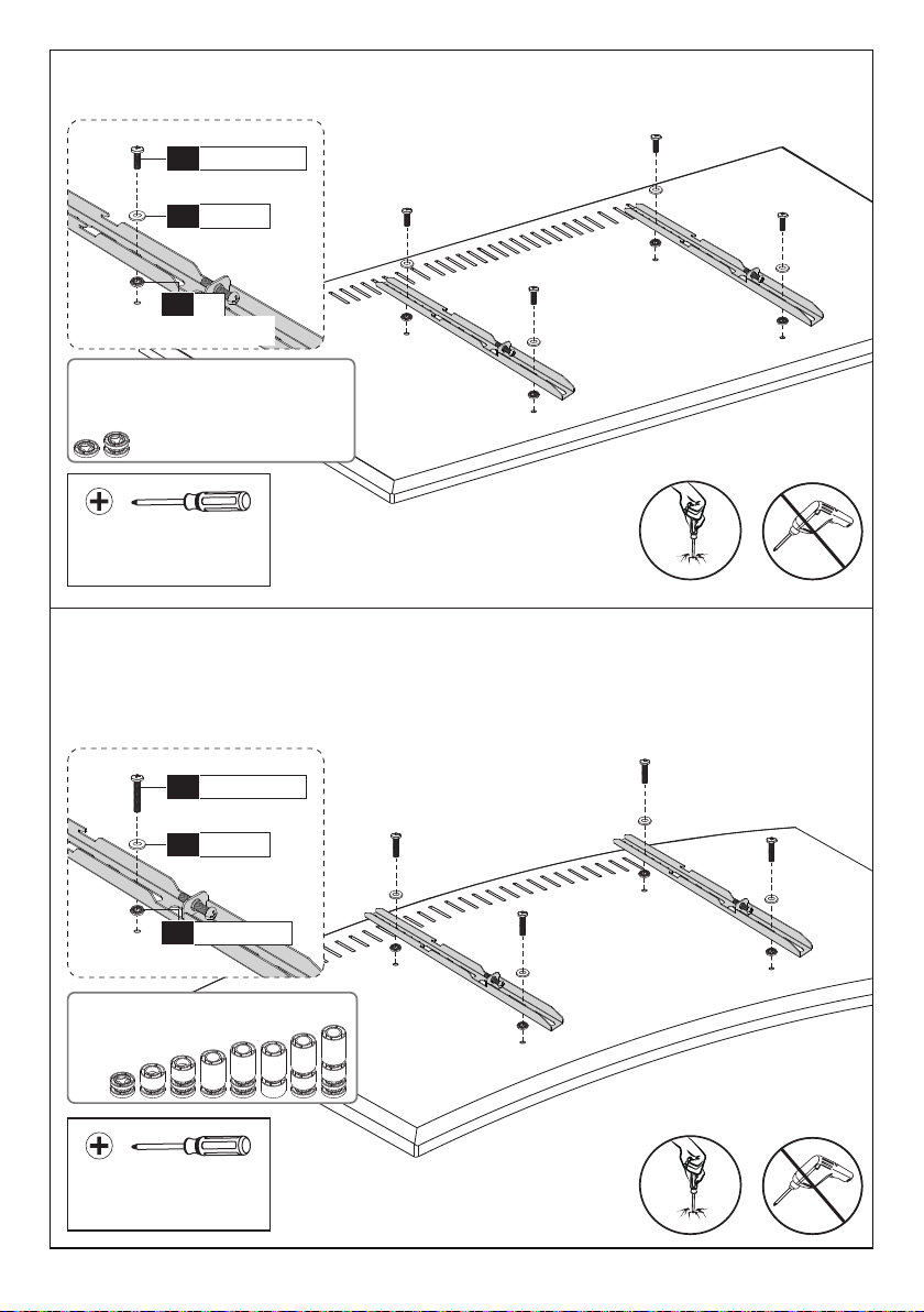
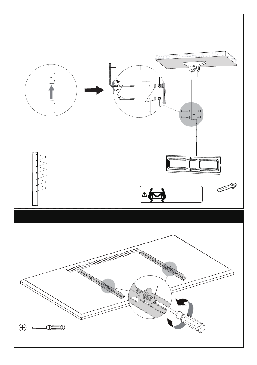
Step 1 Secure the TV Brackets to the TV
Bolt length: Verify adequate thread engagement with bolts or bolts/spacers
combination. We recommend thread engagement by at least 5 turns.
-Too short will not hold the TV.
-Too long will damage the TV.
NOTE: Please do not over tighten the TV bolts to avoid damaging your TV.
[C1] x4
M4x12mm
[C2] x4
M4x30mm
M6x15mm
[D1] x4
M6x35mm
[D2] x4
[E2] x4
M8x50mm
M8x25mm
[E1] x4
04

PLEASE NOTE: If Spacers are required for your installation, a combination of
different Spacers can be stacked to obtain a proper length. See examples in the
image below. If you have any difficulty understanding how to install the TV Bolts or
Spacers, please contact our Technical Support at (877) 419-7832 or Customer
Too Short Correct Too Long
Parts Needed if You Have a TV as Shown Below
Recessed Holes
See Option E
Cables See
Option D
Bump See
Option C
Curved TV See
Option B
Spacers
F1+F1 F1+F2 F1+F1+F2 F1+F1+F3 F1+F2+F3F2+F3 F1+F1+F2+F3F1+F3
CAUTION: When attaching the TV
Brackets to the back of the TV,
ensure the end with round holes on
the TV Brackets are pointing to the
top of the TV and are equally centered
on the back of the TV.
PLEASE NOTE: The bolt hole
locations on your TV may vary in
accordance with the manufacturer's
design of the TV. We are only
illustrating possible locations
of the bolt holes.
UP
05
C1/D1/E1
06
B1/B2
04
F1
05
(If needed)
Option A (For Flat Back TV)
Refer back to Spacer Instructions
on Page 5, If needed
Phillips Screwdriver
(Not lncluded)
D
o
n
o
t
o
v
e
r
-
t
i
g
h
t
e
n
Spacers must be tall enough so that the curve on the back
of the TV will not interfere with the mounting plate.
D
o
n
o
t
o
v
e
r
-
t
i
g
h
t
e
n
Option B (For Curved Back TV)
Refer back to Spacer Instructions
on Page 5, If needed
C2/D2/E2
06
B1/B2
04
F1/F2/F3
05
Phillips Screwdriver
(Not lncluded)
06

Refer back to Spacer Instructions
on Page 5, If needed
Phillips Screwdriver
(Not lncluded)
03
F1/F2/F3
05 B1/B2
04
C2/D2/
E2
06
Option C (For TV with A “Bump”)
D
o
n
o
t
o
v
e
r
-
t
i
g
h
t
e
n
Refer back to Spacer Instructions
on Page 5, If needed
C2/D2/E2
06
B1/B2
04
F1/F2/F3
05
Phillips Screwdriver
(Not lncluded)
For cable interference, use Spacers [F1], [F2] and [F3] to create extra space
between the TV and TV brackets.
Option D (for TV with Cable Interference)
D
o
n
o
t
o
v
e
r
-
t
i
g
h
t
e
n
Spacers must be tall enough so there is no gap between TV bracket and
bump on the back of the TV.
07

Supplied Parts and Hardware for Step 2
Option E (For Recessed Holes )
F1/F2/F3
05
C2/D1/
E2
06
B1/B2
04 03
The Spacers need to fill in the recessed holes on the back of the TV so that
the TV Brackets are as close to the TV as possible.
D
o
n
o
t
o
v
e
r
-
t
i
g
h
t
e
n
Refer back to Spacer Instructions
on Page 5, If needed
Phillips Screwdriver
(Not lncluded)
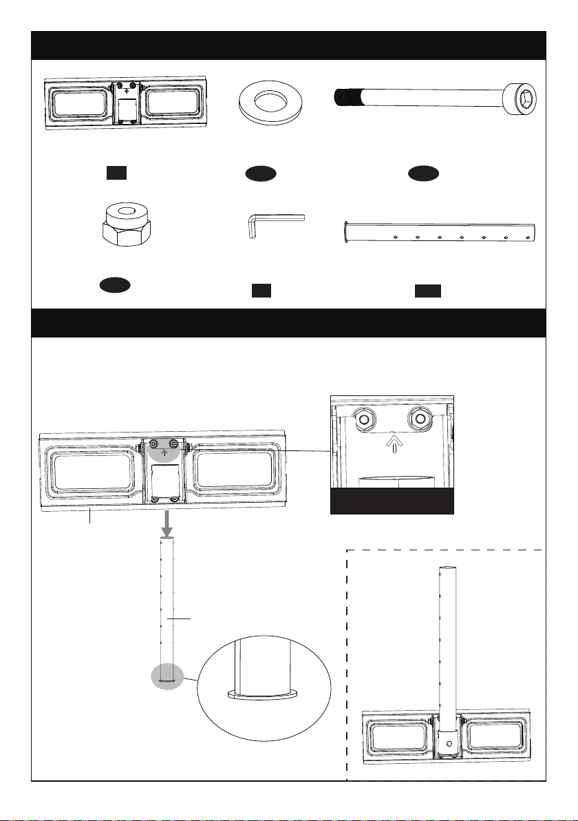
08 x1
3/16 in(5mm)
Allen Key
02 x1
Ceiling Plate
Bolt
M6x12mm
x2
b1 x2
b2
Washer
22x6.4
x1
b3
M6 Washer
01 x1
Upper Pole
x1
b4
Bolt
M6x60mm M6 Nut
x1
b5
08
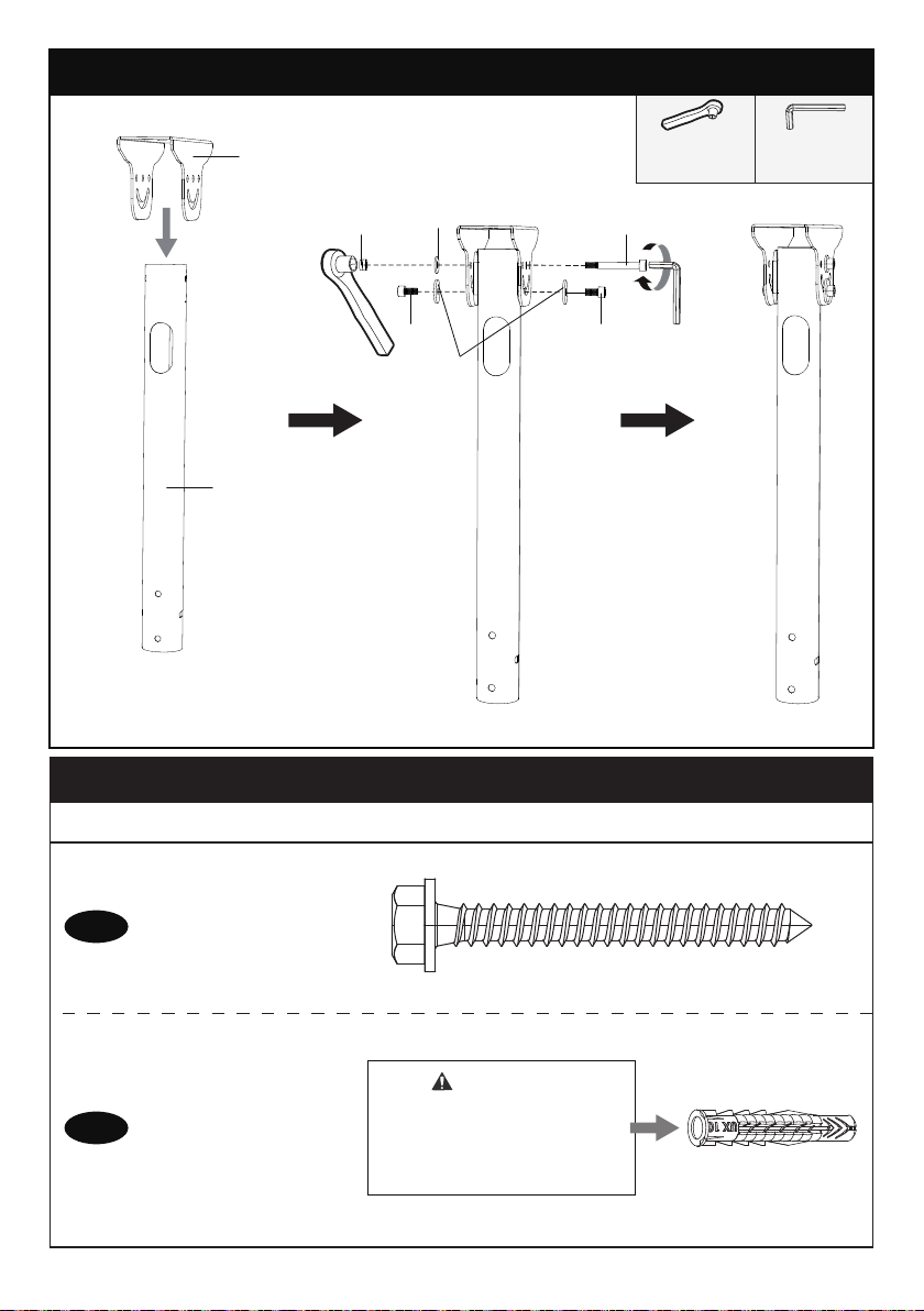
A1
Anchor
10X60 mm
x4
A2
CAUTION!
This Anchor is for concrete
ceiling ONLY. DO NOT use
them in drywall or ceiling
joist.
Supplied Hardware for Step 3
x4
NOTE: The lag screw is shown in actual size.
3/8” (10mm)
Socket Wrench
(NOT Included)
Step 2 Attach the Ceiling Plate to the Top of the Upper Pole
3/16” (5mm)
Allen Key
[05]
Lag Screw
5/16” x 2 3/4"
02
b4b5
b2
b3
b1b1
01
09
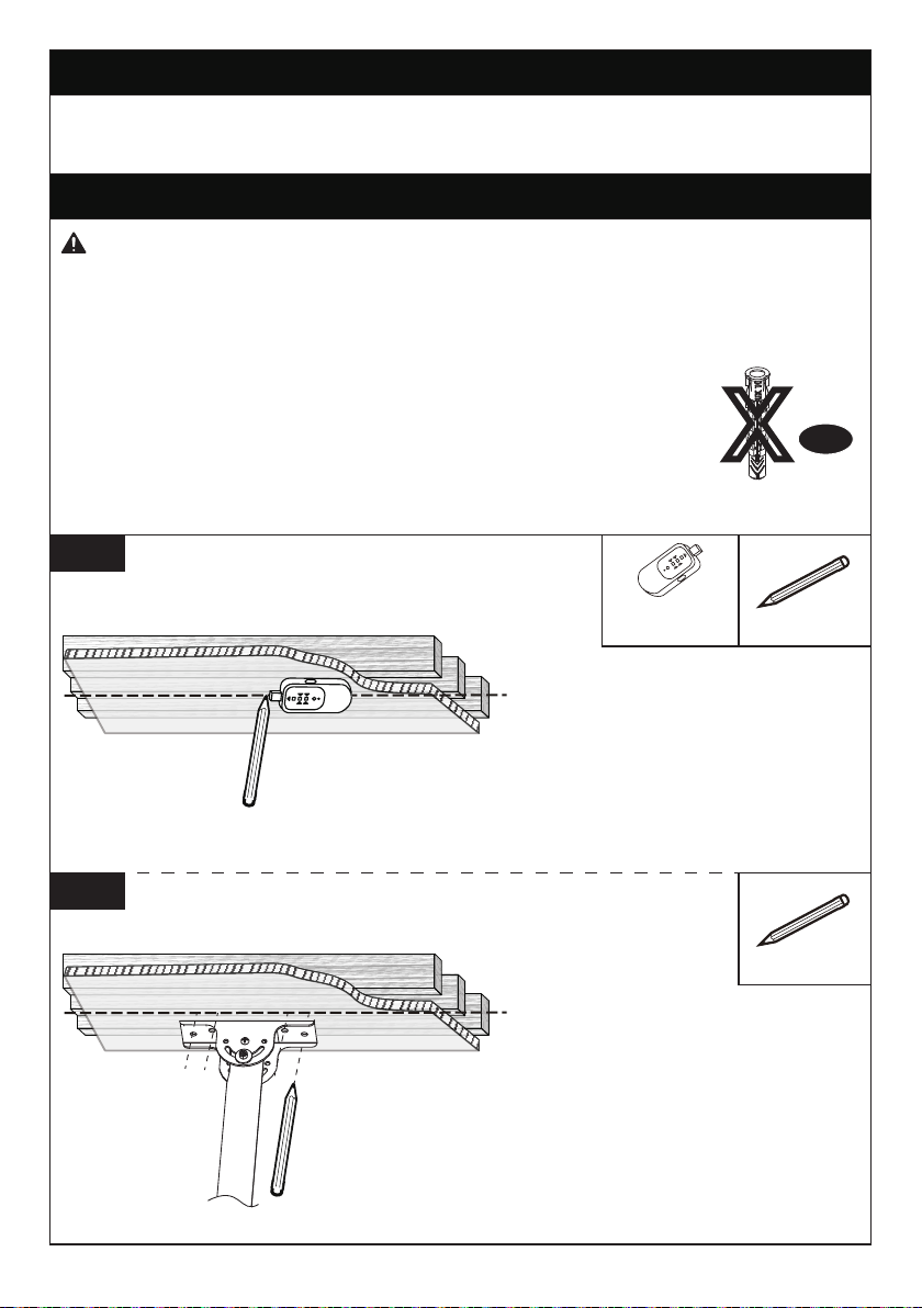
Step 3 Secure the Ceiling Plate to the Ceiling
For wood stud installation, follow STEP 3A
For concrete installation, follow STEP 3B
Use a Stud Finder (not included)
to locate ceiling joist to verify
the edges. Mark the edge and
center locations.
3A-1
Step 3A Wood Stud Option
● To avoid personal injury or property damage, Do Not over-tighten the Lag
Screws [A1]. Using a self-supplied socket wrench, tighten the Lag Screws [A1]
only until they are pulled firmly against the Ceiling Plate and ceiling.
● DO NOT USE ANCHOR FOR THIS STEP.
● Ensure the Ceiling Plate is securely fastened to the ceiling
before continuing to the next step.
● Nominal ceiling joist size: common 2” x 8” (51mm x 203mm) .
● Stud center must be verified.
● Do not use a drill for tightening the Lag Screws!
● Only use a Socket Wrench.
WARNING:
Anchor
XA2
Position the Ceiling Plate [02]
at your desired position, and
mark the pilot hole locations.
3A-2
Stud Finder
(NOT lncluded)
Pencil
(NOT Included)
Pencil
(NOT Included)
10

Install the Ceiling Plate [02] using
Lag Screws [A1]. Tighten the Lag
Screws [A1] only until they are
pulled firmly against the Ceiling
Plate. DO NOT over-tighten the
Lag Screws.
3A-4
CAUTION: DO NOT use a drill to
tighten the Lag Screws. Only use
a Socket Wrench.
1/2" (13mm)
Socket Wrench
(NOT Included)
Drill 4 pilot holes using a 7/32"
(5.5mm) diameter drill bit. Make
sure the depth of the pilot holes
is at least 2 3/4" (70mm) deep.
3A-3 2 3/4" (70mm)
7/32" (5.5mm)
WARNING:
Step 3B Solid Concrete Ceiling Option
● To avoid personal injury or property damage, Do Not over-tighten the Lag
Screws [A1]. Using a self-supplied Socket Wrench, tighten the Lag Screws [A1]
only until they are pulled firmly against the Ceiling Plate and ceiling.
● Ensure the Ceiling Plate is securely fastened to the ceiling
before continuing to the next step.
● Mount the Ceiling Plate [02] directly onto the concrete
surface without any covering.
● The thickness of the ceiling must exceed 5 1/2" (140mm).
● Do not use a drill for tightening the lag screws! Only use a socket wrench.
Anchor
A2
CAUTION:
DO NOT drill the holes at the
edge of the ceiling joist. Make
sure the holes are drilled on the
center location of the ceiling joist.
Electric Drill
(NOT Included)
A1
11

3” (75mm)
3/8” (10mm)
CAUTION: DO NOT use a drill to
tighten the Lag Screws. Only use
a Socket Wrench.
1/2" (13mm)
Socket Wrench
(NOT Included)
Position the Ceiling Plate [02]
at your desired position, and
mark the pilot hole locations.
Drill the 4 pilot holes using a
3/8” (10mm) diameter drill bit.
Make sure the depth of each
hole is at least 3" (75mm) deep.
3B-1
3B-2
3B-3
3B-4
Install the Ceiling Plate [02] using
Lag Screws [A1]. Tighten the Lag
Screws [A1] only until they are
pulled firmly against the Ceiling
Plate.
Ceiling Thickness
≥5 1/2" (140mm)
Use the Hammer to knock
Anchors [A2] into the ceiling. Be
sure the Anchors [A2] are seated
flush with the concrete surface.
Pencil
(NOT Included)
Electric Drill
(NOT Included)
A1
Hammer
(NOT Included)
12
Supplied Parts and Hardware for Step 4
09 x1
Lower Pole
Step 4 Secure Poles with TV Plate to the Lower Pole
4-1 Slide the TV Plate [07] onto the Lower Pole [09].
x2
b3
M6 Washer
07 x1
TV Plate
M6 Nut
x2
b5
x2
b4
Bolt
M6x60mm
08 x1
3/16 in(5mm)
Allen Key
09
Keep arrow up
07
13
4-2 Align the holes in the Lower Pole [09] with the holes in the Upper Pole [01].
Height adjustments can be made by selecting different holes in Lower Pole [09].
Using Bolts [b4], Washers [b3], and Nuts [b5], attach the poles together at desired
height. Hold Bolts [b4] with supplied Allen Key [05] while using a self-supplied Socket
Wrench to tighten Nuts [b5].
3/8” (10mm)
Socket Wrench
(NOT included)
HEAVY! You may
need assistance
with this step.
01
09
08
b3b4
b3
b3 b4b5
b4b5
01
09
NOTE: There are six mounting
locations for the Lower Pole [09] which
will determine the height of your TV.
Mounting Location #1
Mounting Location #2
09
Mounting Location #3
Mounting Location #4
Mounting Location #5
Mounting Location #6
Step 5 Secure the TV to Front Support
Phillips Screwdriver
(NOT lncluded)
Step 5-1 Slightly unscrew the pre-assembled
Bolt [K] with self-supplied Philips Screwdriver
until it is seated flush with plate.
Loosen
K
14
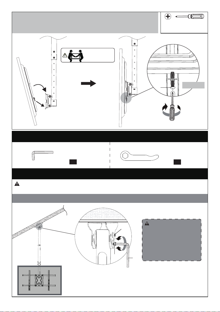
Step 5-2 Hang the TV on the TV Plate.
Step 5-3 Tighten the Bolts [K] on the safety locks into place
until they are pulled firmly against the TV Plate.
HEAVY! You may
need assistance
with this step.
Phillips Screwdriver
(NOT lncluded)
Step 5-2
K
Locking
Step 5-3
Adjustment for Non-Level Ceilings
Step 6 Adjustments
1. Slightly loosen the Bolt [b1] with the Allen Key [08].
2. Adjust the mount until it hangs down vertically.
3. Tighten the Bolt [b1] to secure the tilt angle into
place.
b1
b4
08
WARNING: To avoid personal injury and property damage, DO NOT loosen Bolt [b4]
during the adjustment for non-level ceilings.
WARNING:
Bolt [b4] should not be
loosened in this step as
it could cause the TV to
fall and cause injuries to
people and property.
Supplied Hardware for Step 6
08 x1
3/16 in(5mm)
Allen Key
7/16 in(11mm)
Wrench
10
x1
15
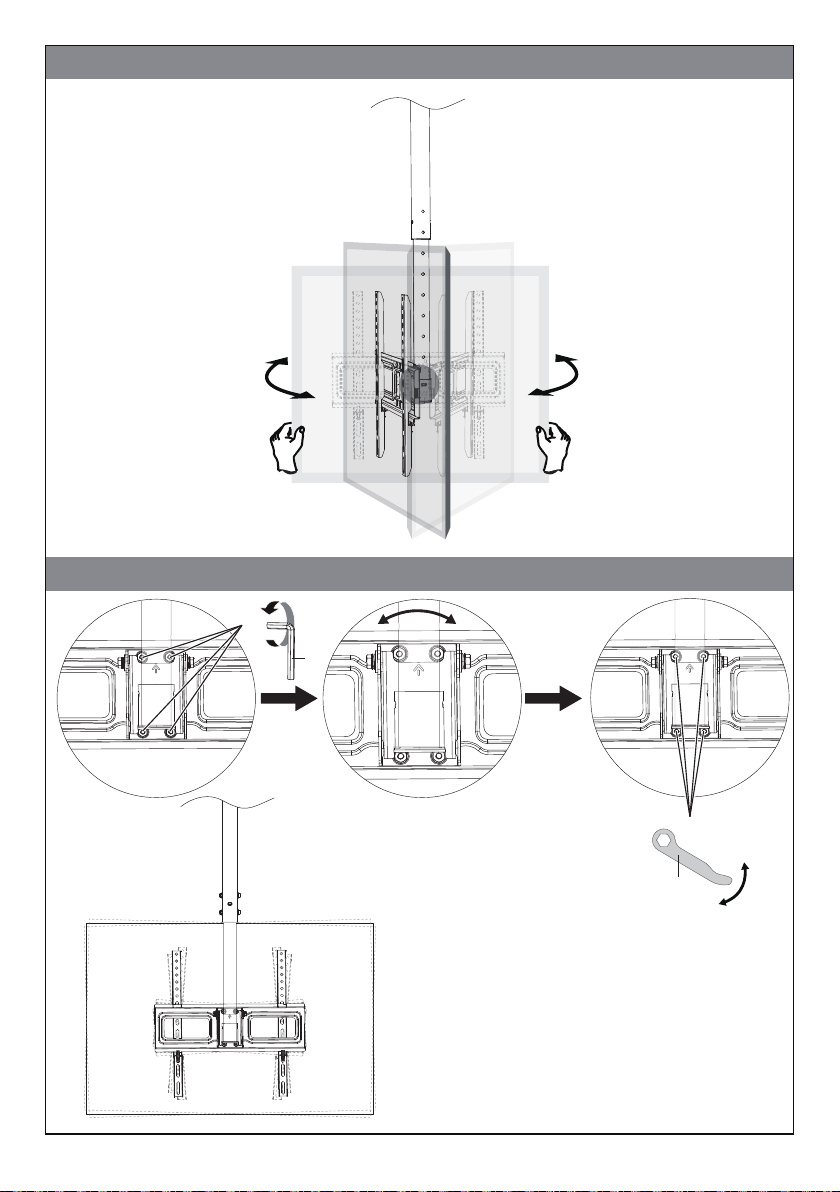
Level Adjustment for TV
1. Slightly loosen the four pre-assembled
Bolts [b7] with the Wrench [10].
2. Adjust the TV to your desired position.
3. Tighten the Bolts [b7] to secure the tilt
angle into place.
08
b7
b7
10
Swivel Adjustment for TV
Tighten
Loosen
16

Tilt Adjustment for TV
1. Slightly loosen the two upper
pre-assembled bolts [T] with a
Wrench [10].
2. Adjust the TV to your desired
position.
3. Tighten the Bolt [T] to secure
the tilt angle into place.
T
Step 7 Route the Cables along with the Pole
NOTE: To prevent excess stress
on connectors and cables, leave
some slack in the cables during
the routing of cables. Always
check connections and cables for
stress and possible mechanical
damage when rotating the TV.
Tighten
Loosen
Loosen
17


9501 Louisiana Ave N, #200, Brooklyn Park, MN 55445
ErgoAV Customer Care
Phone (877) 419-7832
At ErgoAV, we strive to provide the highest value products.
We want to support your purchase.
If you have questions,concerns,
or feedback please let us know!
WWW.ERGOAV.COM
Speaker Stands Tabletop TV StandComputer Monitor Mounts
This manual suits for next models
1
Table of contents
Other ErgoAV TV Mount manuals

ErgoAV
ErgoAV ERDHM1-01B User manual

ErgoAV
ErgoAV ERTSM2-01B User manual

ErgoAV
ErgoAV ERMMS1 -01 B User manual

ErgoAV
ErgoAV ERMTM2-01B User manual

ErgoAV
ErgoAV ERMTM2-01B User manual

ErgoAV
ErgoAV ERMTM1-01B User manual

ErgoAV
ErgoAV ERTSS2-01B User manual

ErgoAV
ErgoAV ERMTS1-01B User manual

ErgoAV
ErgoAV ERMTL1-01B User manual

ErgoAV
ErgoAV ERDHM2-01B User manual


