DESCRIPTION
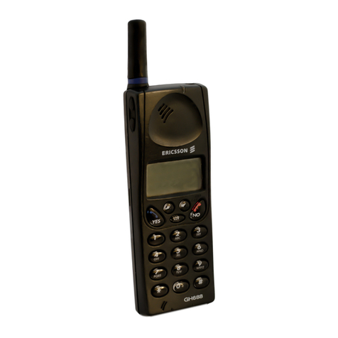
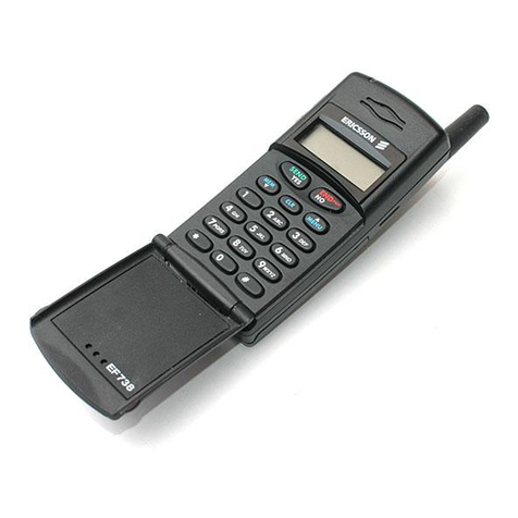
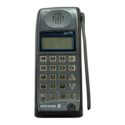
The handsets, shown in Figure 1, consists of a single printed
circuit board containing the following:
•Numerical and function keypad
•Liquid Crystal Display
•All audio and logic circuitry
The printed circuit board contains the microphone preampli-
fier, earpiece amplifier, speaker amplifier, keypad switches, a
microcomputer and LCD driver, receive and transmit data buff-
ers, a 5 volt regulator and backlight LED’s and circuitry.
Although the Basic (19A705860P1) and Extended
(19A705870P1) models of the handset differ in external appear-
ance, they are the same electronically. The Extended model has
oneextrakey"A-Z"and indicators for"HORN","LOCK"and
"MUTE".
Audio from the electret microphone (B1) is amplified by
U1-A and passed to the transmit audio path of the radio.
Fourbitmicrocomputer U5(MB88543)scansthekeypadand
controls the LCD. The microcomputer also controls the LED
backlighting of the display and keypad. When a key is pressed
on the keypad, an ASCII code isgenerated by the microcomputer
and serially transmitted to the mobile. The key release and a
hookswitch change also send ASCII codes to the mobile. At
power-up thehandset sends a code to identify itself. The handset
receives commands from the mobile to control the display (indi-
cators, alpha and numeric characters) control the call timer, turn
backlight on or off and interrogates status of handset or hook-
switch.
TEST SPECIFICATIONS
MICROPHONE
1. Sensitivity - An input level of 97 dB SPL produces
an output of 150 mV rms ±5 dB. [dB SPL = 20
LOG 10 (P/Po): Pis the rms sound pressure in
Pascals and Po = 2 X 10⁻⁵ Pascal]
2. Distortion - For an input signal of less than 1%
distortion, the output distortion does not exceed 3%
from 300 Hz to 3000 Hz.
RECEIVER
1. Off Hook Sensitivity- A one (1) kHz, 100 mV rms
input signal produces an output of 94 ±3 dB SPL,
measured at the artificial ear.
2. Distortion- For an input signal of 100 mV rms with
less than 1% distortion, the output distortion is less
than 5% as measured at the artificial ear from 300
Hz to 3000 Hz.
3. Ear Protection - An audio limiter is provided to
ensure that the maximum acoustic output does not
exceed 120 dB SPL.
4. On Hook Sensitivity - A 1 kHz tone, 100 mV rms
input signal produces an output of 80 ±6 dB SPL
as measured in the free field.
SIDETONE LEVEL
The acoustic to acoustic sidetone response is such that a 1000
Hz, 97 dB SPL transmit audio input signal produces 85 ±6 dB
SPL at the artificial ear.
ON/OFF
There is a momentary switch in the handset that is sensed in
the mobile to control the 12 V supply to the handset.
SERIAL DATA
The serial data format is a pseudo RS-232 format. Specifi-
cally, it is an asynchronous serial bus operatingbetween Vccand
0 volts.
Baud Rate 300 ±5%
Bit Pattern One (1) start two (2) stop, eight (8)
data and no parity.
Format 0 to Vcc invertedwithVccbeingano
data condition.
Vcc 4.5 to 6.0 Vdc
Keypad Data High-Open Collector drive less than
50 mA current drain.
Display Data
High Open Collector drive less than 50
mA current drain
Low 0.8 V maximum
Copyright © January 1991, Ericsson GE Mobile Communications Inc.
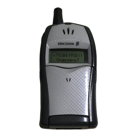
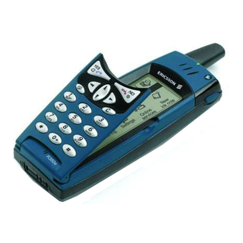
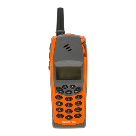
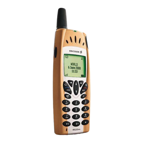
Figure 1 - Basic (19A705860P1) And Extended (19A705870P1) Handsets
LBI-38412
1

