Ericsson 2400 User manual

LBI-33031B
ericssonz
Maintenance Manual
Rockwell Modem
Model R96FT (19A705178)
U.S. Robotics Courier Modem
Model 2400 (19A149786P1)
Model V.32 (19A149786P2)

GENERAL
m
m
ELECTRIC
19A705178
REV NO. TITLE CONT ON SHEET 3SH NO. 2
ROCKWELL MODEM TEST
SPECIFICATION/PURCHASE PART DRAWING
CONT ON SHEET SH NO. FIRST MADE FOR F. C. F. O.
MADE BY K P Dotson 11-19-86 APPROVALS
DCB M. R. P. D. DIV OR DEPT. 19A705178
ISSUED Nov. 19, 1986 11-18-86 LYNCHBURG LOCATION CONT ON SHEET 3SH NO. 2
REVISIONS
L30
PRINTS TO
TABLE OF CONTENTS
1.0 SCOPE
2.0 DESCRIPTION
2.1 GETC SHELF
2.2 ROCKWELL MODEM BOARD
2.3 TEST SOFTWARE
3.0 SPECIFICATIONS
3.1 POWER SUPPLY
3.2 DATA TRANSMISSION
3.3 APPLICABLE DRAWINGS
4.0 TEST EQUIPMENT
5.0 TEST PROCEDURES
5.1 TEST PREPARATION
5.2 ROCKWELL MODEM TEST
6.0 PART DRAWING
6.1 VENDOR SPECIFICATION
6.2 MODEM TECHNICAL SPECIFICATIONS

GENERAL
m
m
ELECTRIC
19A705178
REV NO. TITLE CONT ON SHEET 4SH NO. 3
ROCKWELL MODEM TEST
SPECIFICATION/PURCHASE PART DRAWING
CONT ON SHEET SH NO. FIRST MADE FOR F. C. F. O.
MADE BY K P Dotson 11-19-86 APPROVALS
DCB M. R. P. D. DIV OR DEPT. 19A705178
ISSUED Nov. 19, 1986 11-18-86 LYNCHBURG LOCATION CONT ON SHEET 4SH NO. 3
REVISIONS
L30
PRINTS TO
1.0 SCOPE
This document describes how to test the Rockwell Modem (R96FT) to insure operation of the 9600 bps serial data
transmission used in the Public Service Trunked System and Voice Guard®System.
Mechanical and Electrical specifications are also included mounting holes and overall dimensions are on Sh. 9 of
this drawing.

GENERAL
m
m
ELECTRIC
19A705178
REV NO. TITLE CONT ON SHEET 5SH NO. 4
ROCKWELL MODEM TEST
SPECIFICATION/PURCHASE PART DRAWING
CONT ON SHEET SH NO. FIRST MADE FOR F. C. F. O.
MADE BY K P Dotson 11-19-86 APPROVALS
DCB M. R. P. D. DIV OR DEPT. 19A705178
ISSUED Nov. 19, 1986 11-18-86 LYNCHBURG LOCATION CONT ON SHEET 5SH NO. 4
REVISIONS
L30
PRINTS TO
2.0 DESCRIPTION
The Rockwell Modem (R96FT) is a purchased part from the Rockwell Corporation used in the GETC™ shelf. The
Rockwell Modem is used to transmit and receive 9600 bps serial data to and from four-wire dedicated unconditioned
telephone 1ines under control of the GETC shelf.
2.1 GETC SHELF
The GETC shelf (19D901868) is used to test the Rockwell Modem as part of the shelf assembly.
2.2 PHONE MODEM BOARD (ROCKWELL R96FT)
The Rockwell R96FT is a board level synchronous serial 9600 bit per second modem. The GETC logic
board contains phone 1ine interface circuits (T1, T2 etc.) that couple the phone modem to the phone line.
2.3 TEST SOFTWARE
The GETC shelf is used as a test fixture for the test of the Rockwell Modem.
The GETC exercises the testing of the Rockwell Modem via the built in test software known as SIMON on
the GETC.

GENERAL
m
m
ELECTRIC
19A705178
REV NO. TITLE CONT ON SHEET 6SH NO. 5
ROCKWELL MODEM TEST
SPECIFICATION/PURCHASE PART DRAWING
CONT ON SHEET SH NO. FIRST MADE FOR F. C. F. O.
MADE BY K P Dotson 11-19-86 APPROVALS
DCB M. R. P. D. DIV OR DEPT. 19A705178
ISSUED Nov. 19, 1986 11-18-86 LYNCHBURG LOCATION CONT ON SHEET 6SH NO. 5
REVISIONS
L30
PRINTS TO
3.0 SPECIFICATIONS
3.1 POWER SUPPLIES
13.8 volts nominal GETC power supply.
Refer to the GETC test specification (19A705179).
Modem Input Power +5 Volts +/-5% < 700 Ma
+12 Volts +/-5% < 20 Ma
-12 Volts +1-5% < 80 Ma
3.2 DATA RATE
Data Rate 9600 +1 -1 Bit/Second
Input Level Range - 43 dBm to 0 dBm
Output Level 0 dBm
Train Time 30 msec
3.3 APPLICABLE DRAWINGS
DRAWING NO. DRAWING NAME
19D901868 GETC SHELF
19D901855 GETC LOGIC BOARD ASSEMBLY
19D901852 GETC LOGIC BOARD SCHEMATIC DIAGRAM

GENERAL
m
m
ELECTRIC
19A705178
REV NO. TITLE CONT ON SHEET 7SH NO. 6
ROCKWELL MODEM TEST
SPECIFICATION/PURCHASE PART DRAWING
CONT ON SHEET SH NO. FIRST MADE FOR F. C. F. O.
MADE BY K P Dotson 11-19-86 APPROVALS
DCB M. R. P. D. DIV OR DEPT. 19A705178
ISSUED Nov. 19, 1986 11-18-86 LYNCHBURG LOCATION CONT ON SHEET 7SH NO. 6
REVISIONS
L30
PRINTS TO
4.0 RECOMMENDED TEST EQUIPMENT
Refer to the GETC test specification (19A705179).
The test equipment necessary to set up the GETC for the Rockwell Modem
test is listed blow. This setup is performed once on the specified GETC.
QTY EQUIPMENT TYPE
1 6286A DC SUPPLY WITH CURRENT LIMIT (OR EQUIVALENT.)
1 OSCILLOSCOPE MEDIUM BANDWIDTH NON-STORAGE
1 FREQUENCY METER CAPABLE OF MEASURING l2 MHz
1 STANDARD TERMINAL
1 TRIPLETT AC VOLT OHMMETER MODEL 630-PL TYPE 5 or DVM
1 19D901868 GETC shelf
1 PROM with SIMON software (standard Application software)
The equipment necessary to test the Rockwell Modem is a GETC shelf
(19D901868).
The GETC is used as a test fixture.

GENERAL
m
m
ELECTRIC
19A705178
REV NO. TITLE CONT ON SHEET 8SH NO. 7
ROCKWELL MODEM TEST
SPECIFICATION/PURCHASE PART DRAWING
CONT ON SHEET SH NO. FIRST MADE FOR F. C. F. O.
MADE BY K P Dotson 11-19-86 APPROVALS
DCB M. R. P. D. DIV OR DEPT. 19A705178
ISSUED Nov. 19, 1986 11-18-86 LYNCHBURG LOCATION CONT ON SHEET 8SH NO. 7
REVISIONS
L30
PRINTS TO
5.0 TEST PROCEDURES
5.1 PREPARATION FOR TEST
Refer to the GETC test specification for certain alignment procedures prior to testing of the Rockwell
Modem. Set up terminal with 19.2 KBaud rate, odd parity, full duplex, and all upper case letters. Connect
the terminal to the master communication link as follows:
SIGNAL GETC LOGIC TERMINAL
BOARD (D-TYPE CONNECTOR)
TXD J8-1 PIN 3
RXD J8-2 PIN 2
GND J8-3 PIN 7
SIMON is used to test the Rockwell Modem.

GENERAL
m
m
ELECTRIC
19A705178
REV NO. TITLE CONT ON SHEET 9SH NO. 8
ROCKWELL MODEM TEST
SPECIFICATION/PURCHASE PART DRAWING
CONT ON SHEET SH NO. FIRST MADE FOR F. C. F. O.
MADE BY K P Dotson 11-19-86 APPROVALS
DCB M. R. P. D. DIV OR DEPT. 19A705178
ISSUED Nov. 19, 1986 11-18-86 LYNCHBURG LOCATION CONT ON SHEET 9SH NO. 8
5.2 ROCKWELL MODEM TEST
The GETC shelf setup procedures to configure it as the test fixture for the Rockwell Modem follows. These
procedures need to be implemented only once on the specified GETC shelf to be used as the Rockwell
Modem test fixture.
1) Plug the Rockwell Modem into J3 on the GETC test fixture.
2) Install P11 between J11-1 and J11-2 on the GETC logic board.
3) Connect a jumper between J6-7 and J6-9 on the GETC.
4) Connect a jumper between J6-6 and J6-8 on the GETC.
5) Install a 680 ohm resistor (1/4 watt) between J6-8 and J6-9.
6) Adjust R1 to about half range on the GETC.
7) Adjust R2 to about half range on the GETC.
The procedures to test the Rockwell Modem follows:
l) Plug the Rockwell Modem into the test fixture.
2) Apply power (13.8 volts) to the GETC shelf and the SIMON welcome message is displayed on the
terminal. The GETC is DTP switch configured for SIMON operation prior to power up. See
19A701179 for dip switch set-up.
3) Type "TIM 19" on the terminal to set the time delay from RTS to beginning of data to 250
milliseconds.
4) Execute the SIMON command "MDS 1" to select the phone modem for subsequent BER
command.
5) Execute the SIMON command "BER DE-00=10". This command transmits data and
simultaneously checks to see that data is being received. The terminal should respond with the
following: Error Count = 0000 Receive Checksum = 00188123
If the terminal does not respond with the above data, the Rockwell Modem has failed the test and
needs to be returned to the vendor.
The test continually runs, outputting data to the terminal in 10 second intervals.
6) After four consecutive test periods (10 seconds per test period) with data outputted to the terminal,
the test can be terminated by pressing a CTRL Z or the ESC key on the terminal.
REVISIONS
L30
PRINTS TO

GENERAL
m
m
ELECTRIC
19A705178
REV NO. TITLE CONT ON SHEET 10 SH NO. 9
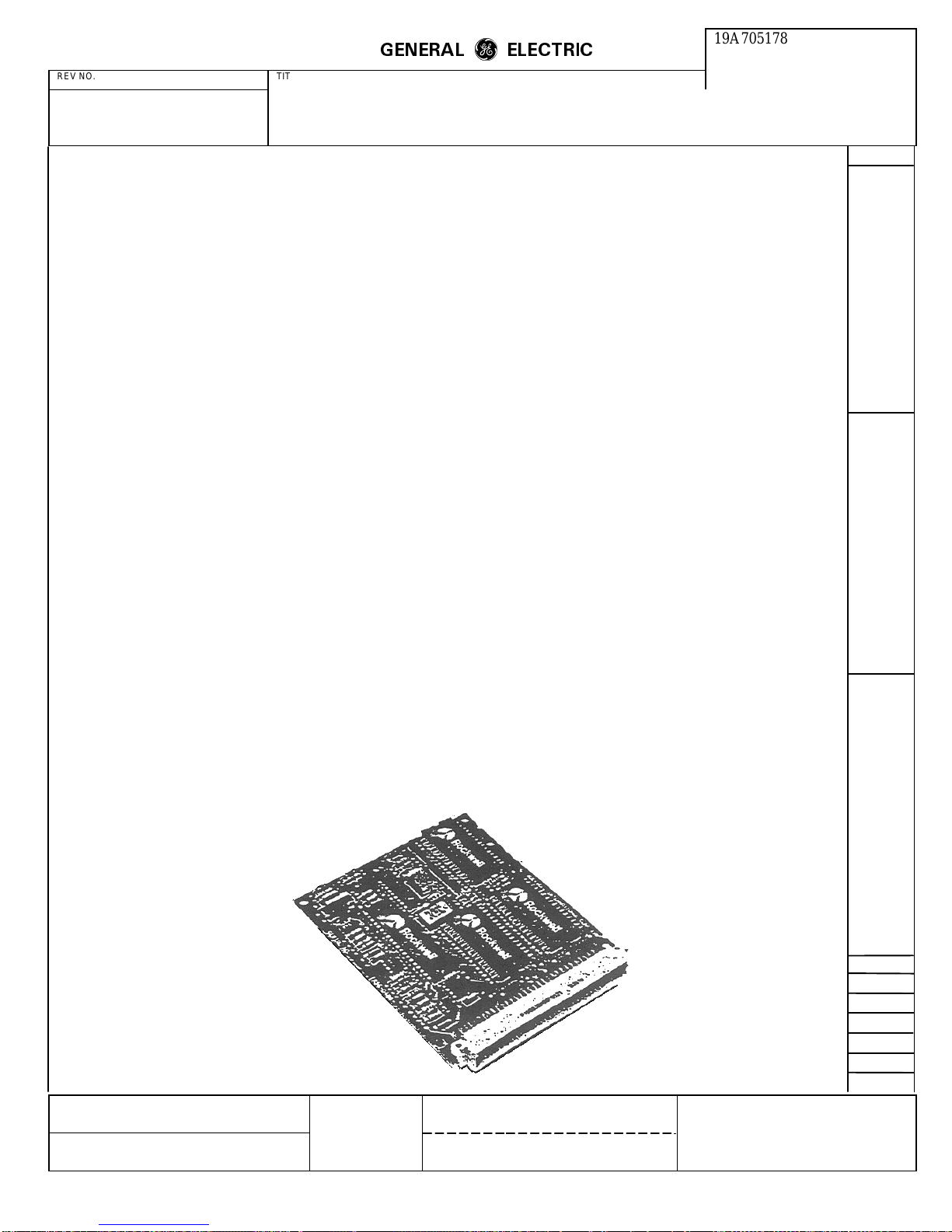
ROCKWELL MODEM TEST
SPECIFICATION/PURCHASE PART DRAWING
CONT ON SHEET SH NO. FIRST MADE FOR F. C. F. O.
MADE BY K P Dotson 11-19-86 APPROVALS
DCB M. R. P. D. DIV OR DEPT. 19A705178
ISSUED Nov. 19, 1986 11-18-86 LYNCHBURG LOCATION CONT ON SHEET 10 SH NO. 9
REVISIONS
L30
PRINTS TO
6.0 PART DRAWING
INTRODUCTION
The Rockwell R96FT is a synchronous serial 9600 bps
modem designed for multipoint and networking
applications. The R96FT allows full-duplex operation over
4-wire dedicated unconditioned lines. or half-duplex
operation over the general switched telephone network.
Proprietary fast train configurations provide training times
of 23 ms for V.29FT/9600/7200/4800, 22 ms for
V.27FT/4800. and 30 ms for V.27FT/2400. A 2400/4800
bps Gearshift configuration provides a training time of 10
ms. For applications requiring operation with international
standards, fallback configurations compatible with CCITT
recommendations V.29 and V.27 bis/ter are provided. A
300 bps FSK configuration, compatible with CCITT V.21
Channel 2, is also provided.
The small size and low power consumption of the R96FT
offer the user flexibility in formulating a 9600 bps modem
design customized for specific packaging and functional
requirements.
This data sheet corresponds to assembly number
TR96D400-061 and subsequent revisions.
FEATURES
• Proprietary Fast Train
• 2400/4800 bps Gearshift
• User Compatibility
– CCITT V.29, V.27 bis/ter and V.21 Channel 2
• Train on Data
• Full-Duplex (4-Wire)
• Half-Duplex (2-Wire)
• Programmable Tone Generation
• Dynamic Range -43 dBm to 0 dBm
• Diagnostic Capability
• Equalization:
– Automatic Adaptive
– Compromise Cable (Selectable)
– Compromise Link (Selectable)
• DTE Interface:
– Microprocessor Bus
– CCITT V.24 (RS-232-C Compatible)
• Loopbacks
– Local Analog (V.54 Loop 3)
– Remote Analog (Locally Activated)
– Remote Digital (Locally ActivatedV.54 Loop 2)
• Small Size
– 100 mm x 120 mm (4.0 in. x 4.8 in.)
• Low Power Consumption
– 3 watts, typical
• Programmable Transmit Output Level
• TTL and CMOS Compatible

GENERAL
m
m
ELECTRIC
19A705178
REV NO. TITLE CONT ON SHEET 11 SH NO. 10
ROCKWELL MODEM TEST
SPECIFICATION/PURCHASE PART DRAWING
CONT ON SHEET SH NO. FIRST MADE FOR F. C. F. O.
MADE BY R Sager APPROVALS
DCB M. R. P. D. DIV OR DEPT. 19A705178
ISSUED Nov. 19, 1986 11-18-86 LYNCHBURG LOCATION CONT ON SHEET 11 SH NO. 10
REVISIONS
L30
PRINTS TO
GENERAL SPECIFICATIONS
POWER
Voltage Tolerance Current (Max.)
+5 Vdc
+12 Vdc
-12 Vdc
±5%
±5%
±5%
<700 mA
<30 mA
<80 mA
Note: All voltages must have ripple ≤0.1 volts peak-to-peak.
ENVIRONMENTAL
Parameter Specification
Temperature
Operating
Storage 0°C to + 60°C (32 to 140°F)
-40°C to +80°C (-40 to 176°F) Stored in heat sealed antistatic
bag and shipping container
Relative Humidity Up to 90% noncondensing, or a wet bulb temperature up to
35°C, whichever is less.
MECHANICAL
Parameter Specification
Board Structure Single PC board with single right angle header with 64 pins.
Burndy P196B32R00A00Z1 or equivalent mating connector.
Dimensions Width - 3.94 in. (100 mm)
Length - 4.72 in. (120 mm)
Height - 0.4 in. (10.2 mm)
Weight Less than 3.6 oz (100g)
This manual suits for next models
2
Table of contents
Other Ericsson Modem manuals

Ericsson
Ericsson HM210dp User manual

Ericsson
Ericsson ZAT 19.2 User manual

Ericsson
Ericsson C3607w User manual

Ericsson
Ericsson F251m User manual

Ericsson
Ericsson F5521gw Parts list manual

Ericsson
Ericsson HM210DP/DI User manual

Ericsson
Ericsson F5521gw User manual

Ericsson
Ericsson PipeRider HM200c User manual

Ericsson
Ericsson HM200c/HM201c User manual

Ericsson
Ericsson HM220d User manual


