Erle Robotics ERLE-COPTER User manual
Erle Robotics
ERLE-COPTER DIY UBUNTU
CORE DRONE KIT
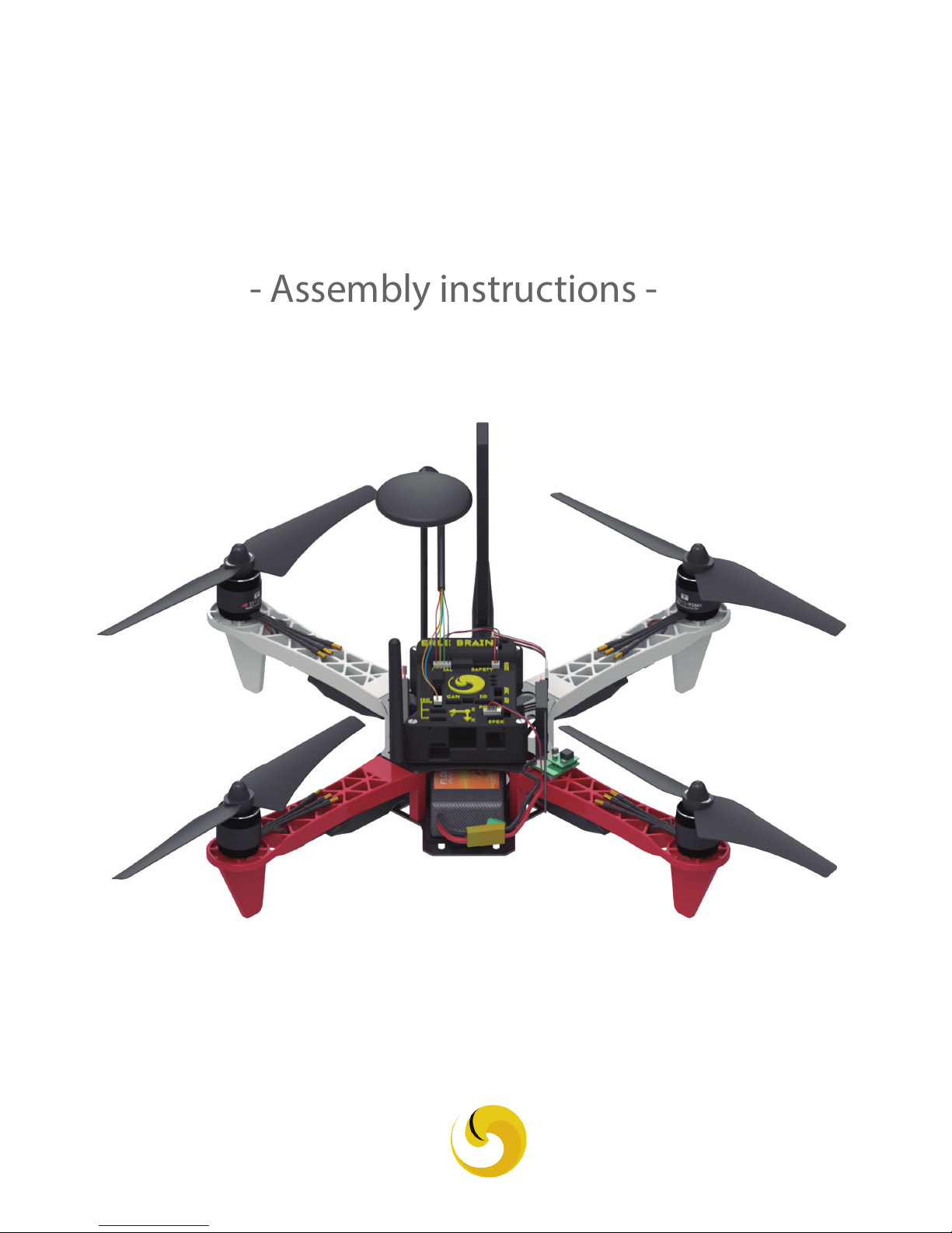
- Assembly instructions -

Do It Yourself
ERLE-COPTER DIY UBUNTU CORE DRONE KIT 2

Necessary tools
Screwdriver (3 types)
Slotted
Hexagon
2mm
Hexagon
2.5mm
Welding station Multimeter
Glue
ERLE-COPTER DIY UBUNTU CORE DRONE KIT 3
Materials
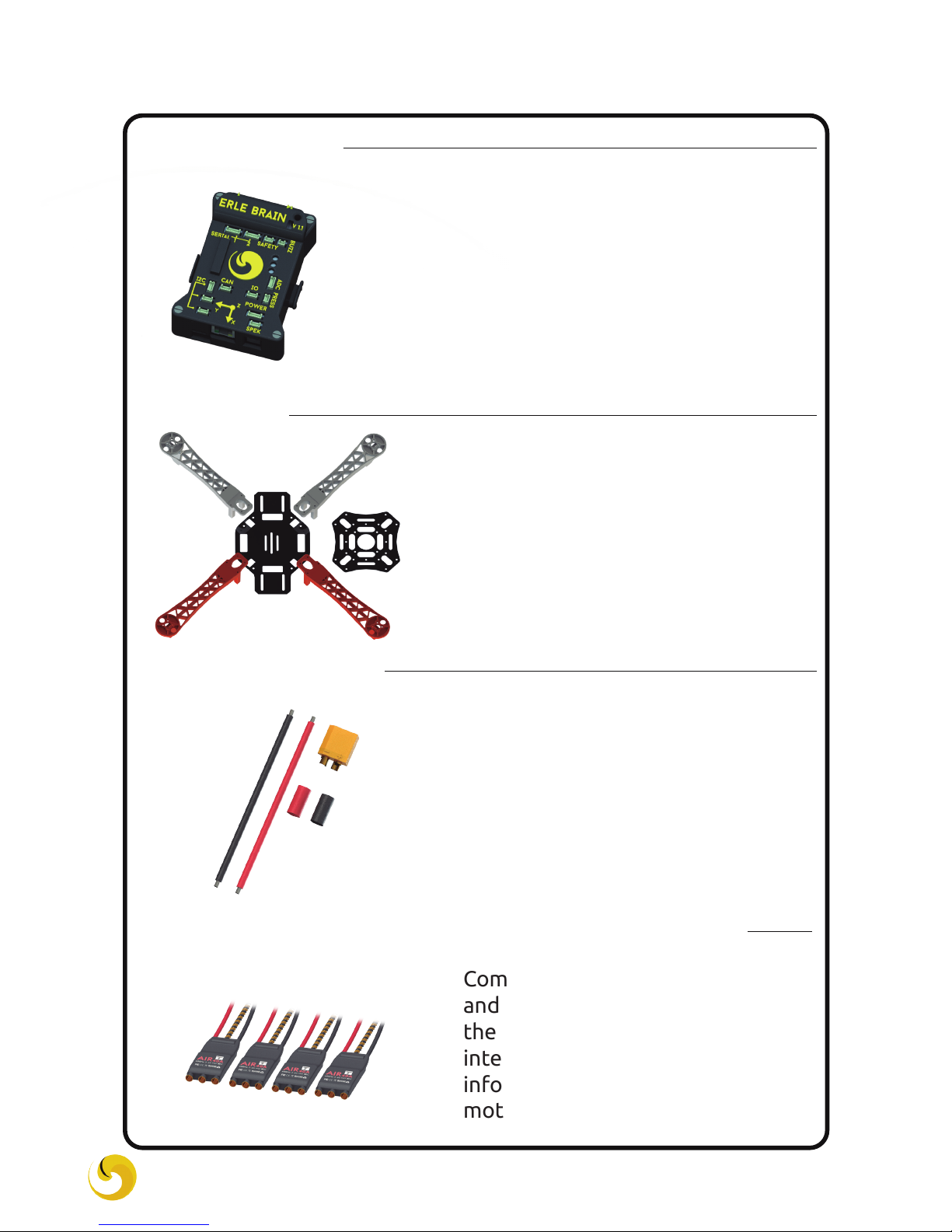
Frame
ESCs (Electronic Speed Controller)
Erle-Brain
XT-60 + wire
ERLE-COPTER DIY UBUNTU CORE DRONE KIT 4
A vehicle frame, also known as its
chassis, is the main supporting
structure of Erle-Copter to which
all other components are attached.
The connector that acts as an
intermediary between the ESCs
and battery. As you will see in the
manual the ESCs and XT-60 are
soldered to the frame, the frame
has a conductive circuit which
distributes the energy entering
through XT-60 to the ESCs.
Erle-Brain is a Linux-based artificial
robotic brain for making robots and
drones with official support for the
Robot Operating System (ROS) and
access to the appstore.
Component that varies the speed
and the direction of rotation of
the motor. That is to say, it is the
intermediary who transmits the
information of Erle-Brain to the
motor.
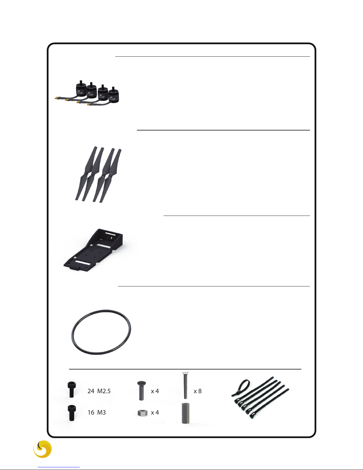
Battery holder
Motors
x 24 M2.5
x 16 M3
x 4
x 4
x 8
x 8
O-ring
Flanges
Propellers
Materials
Converts electrical energy into me-
chanical energy (rotation) and
transmitted directly to the pro-
pellers.
Aircraft propellers or airscrews con-
vert rotary motion from electric
motor, to provide propulsion.
Plastic components to hold the
battery perfectly to the frame using
the Velcro. It is an easy way to
change the battery quickly.
The o-ring is an elastic component
to tie the Erle Brain to the frame. It
offers a versatile way to mount the
Erle-Brain to the frame with
quick-release capability, allowing
you to move your Erle-Brain be-
tween multiple Erle-vehicles.
ERLE-COPTER DIY UBUNTU CORE DRONE KIT 5

Battery
Power Module
RC receiver
GPS + COMPASS
Additional components
The Power Module incorporates
both a way to power your autopilot,
accessories and report battery volt-
age and curret to the PXF. The
on-board switching regulator out-
puts 5.3V at a maximum of a 2.25A,
and can be used up to 18 Volts (4S
LIPo) and at a maximum of 90 amps.
It is ready to use with XT-60.
An electric battery is a device con-
sisting of two or more electrochemi-
cal cells that convert stored chemical
energy into electrical energy.
Receives the radio values from Radio
Control and shares it with Erle-Brain
using PPM encoding.
Determines the position of the
copter and its cardinal orientation. It
must be placed in the highest part of
the vehicle for better satellite
connection and to avoid inter-
ference with Erle-Brain.
ERLE-COPTER DIY UBUNTU CORE DRONE KIT 6
Additional components
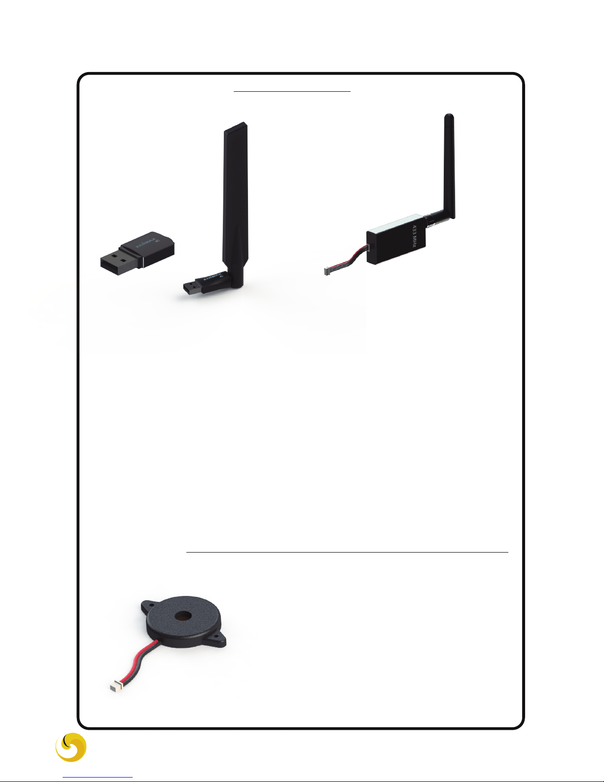
WiFi Dongle Telemetry
Buzzer
ERLE-COPTER DIY UBUNTU CORE DRONE KIT 7
Devices that allow users to wirelessly connect to the copter.
The difference is that the telemetry requires a pair of radios: one
connected to the vehicle and another connected to an external USB
device, such as an computer or a tablet.
Using the WiFi Dongle, Erle-Brain creates a wireless network com-
patible with your existing wifi technology.
Wifi Dongle can be high or low gain, which determines the signal
range.
A buzzer or beeper is an audio piezoe-
lectric signaling device. Erle-Brain uses
the buzzer to signal different events.

1 Soldering the ESCs and the XT-60
Mounting XT-60 male connector
Introduce the wires into the
connector and solder them
Introduce the heat shrinks tube and heat them up
NOTE: It is important to check with the multimeter that the welds are well done
ERLE-COPTER DIY UBUNTU CORE DRONE KIT 8
Attention: Be careful while
soldering, notice that the
solder joints must be small
enough not to obstruct other
frame componentes.
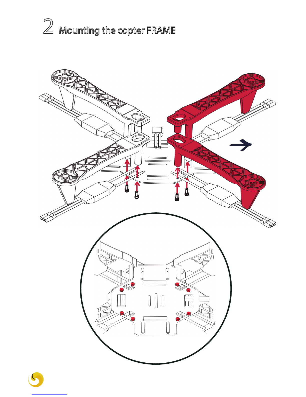
2 Mounting the copter FRAME
FRONT
NOTE: We recommend using red legs for the front and white legs for the
rear of the copter. This will help you identify the front of your copter.
Screw: M2.5
ERLE-COPTER DIY UBUNTU CORE DRONE KIT 9
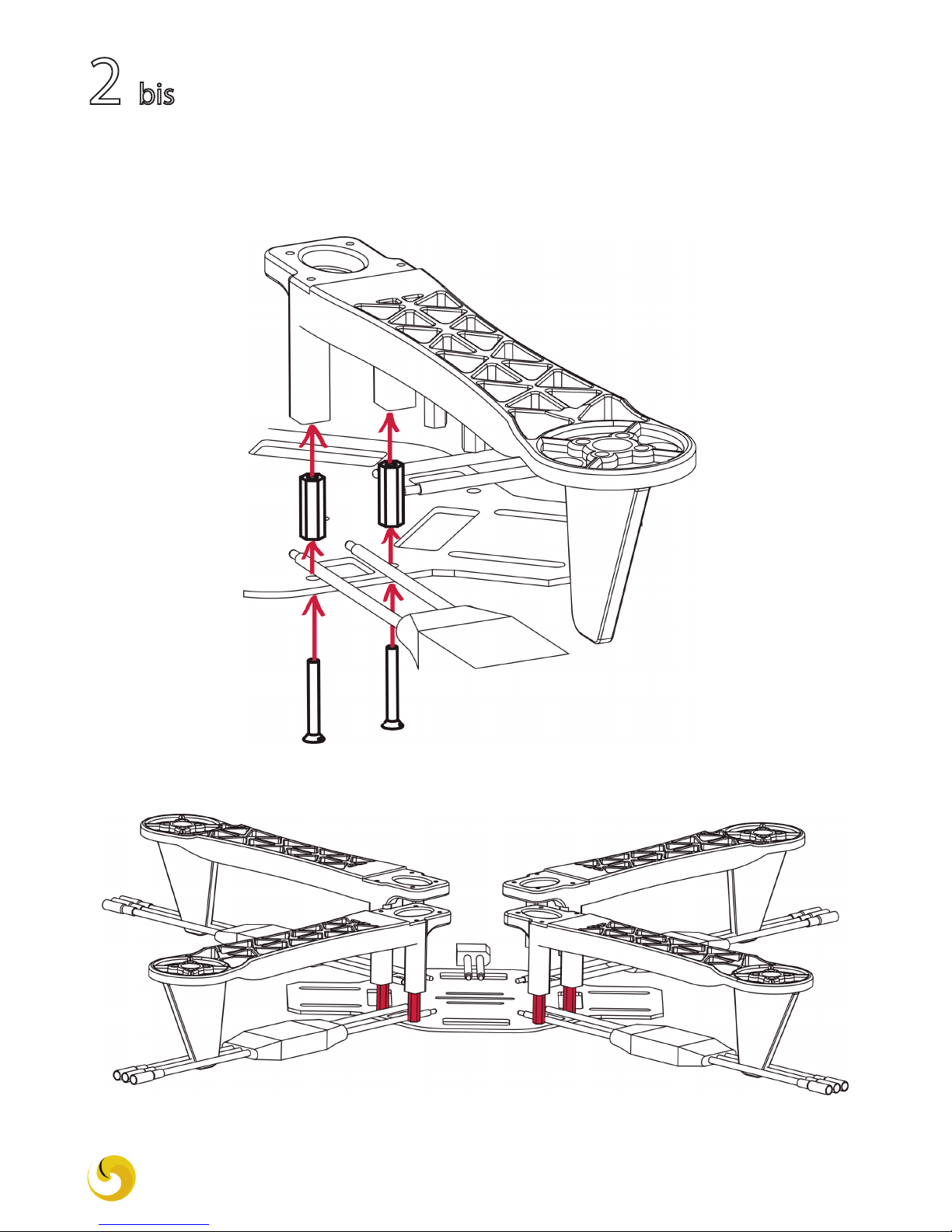
2 bis
Additionally, you can add separators between the legs and the bottom
frame to increase the available space (e.g.: add thicker batteries, place
components inside, etc.)
ERLE-COPTER DIY UBUNTU CORE DRONE KIT 10
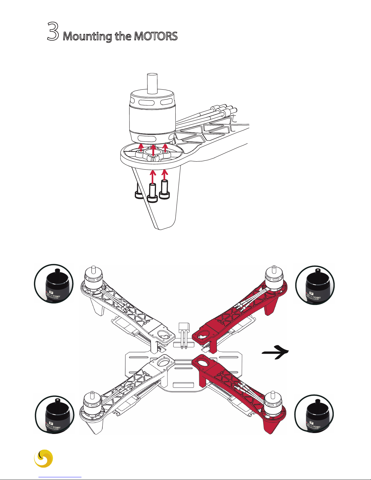
3Mounting the MOTORS
NOTICE: There are two types of motors, those whiththose a white point and
without.
FRONT
Screw: M3
ERLE-COPTER DIY UBUNTU CORE DRONE KIT 11

4BATTERY HOLDER assembly
ERLE-COPTER DIY UBUNTU CORE DRONE KIT 12
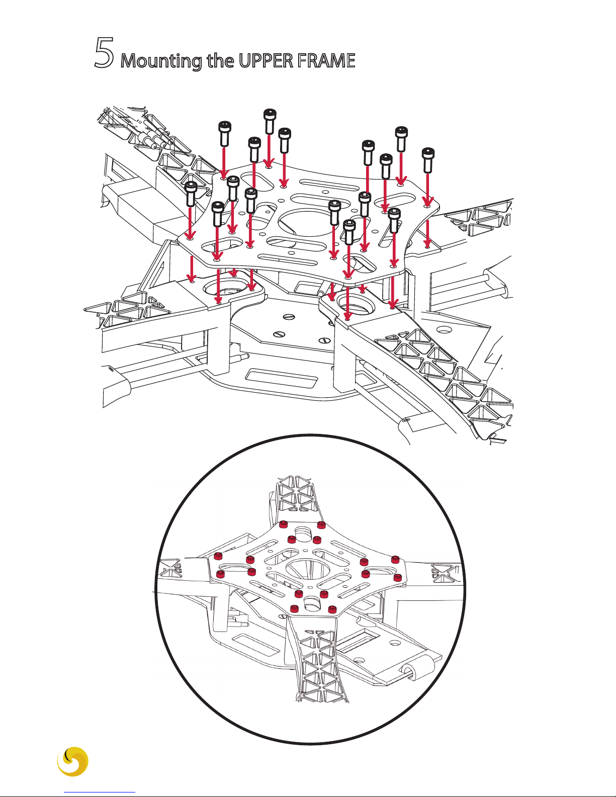
5Mounting the UPPER FRAME
Screw: M3
ERLE-COPTER DIY UBUNTU CORE DRONE KIT 13

6Mounting the AUTOPILOT
FRONT
We will now mount Erle-brain in the copter. The autopilot case has small
aps, used with the o-ring to allow mounting allows to tight it up pretty much
anywhere:
ERLE-COPTER DIY UBUNTU CORE DRONE KIT 14
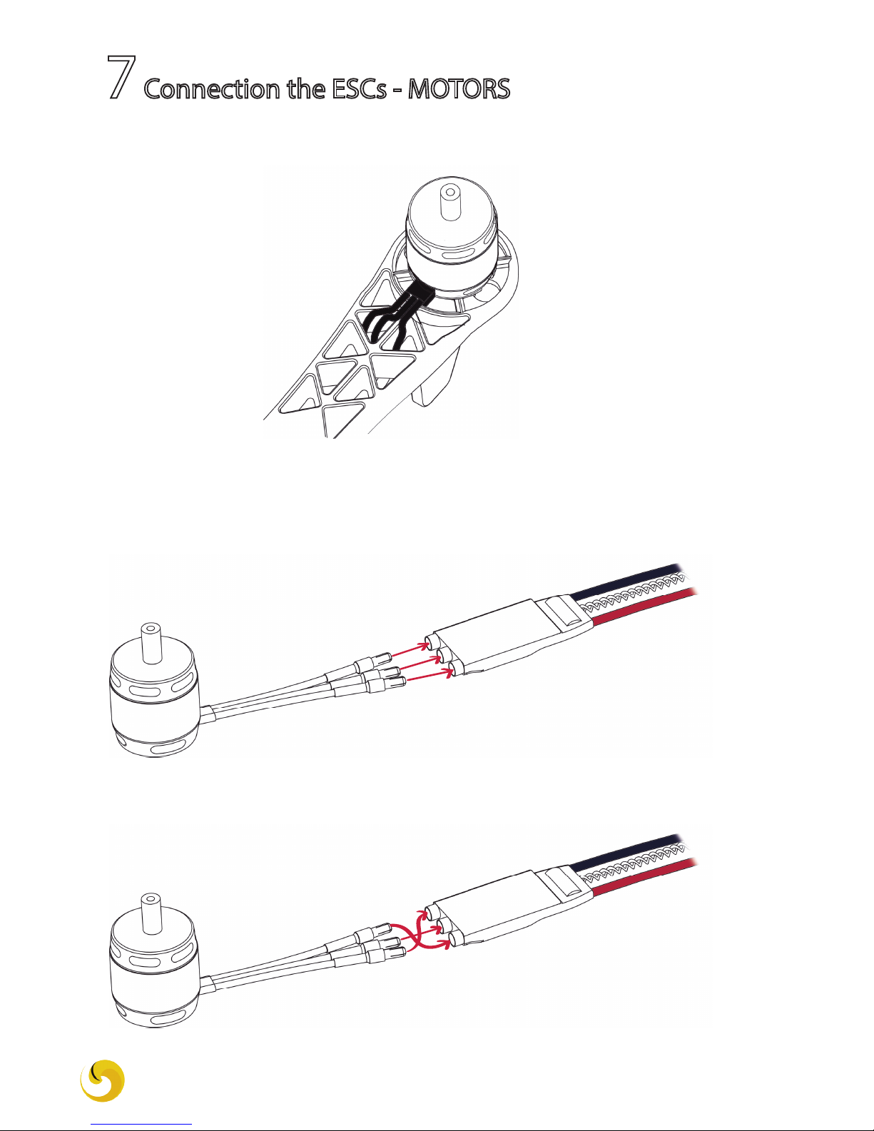
7Connection the ESCs - MOTORS
1. Thread the wires through to the botton of the arms:
2. Depending on the motor type, the ESC wires connection varies:
- The motors with a WHITE POINT connect directly to the ESC.
- For the motors without the white point, you must swap the outer wires before
connecting them to the ESC.
ERLE-COPTER DIY UBUNTU CORE DRONE KIT 15
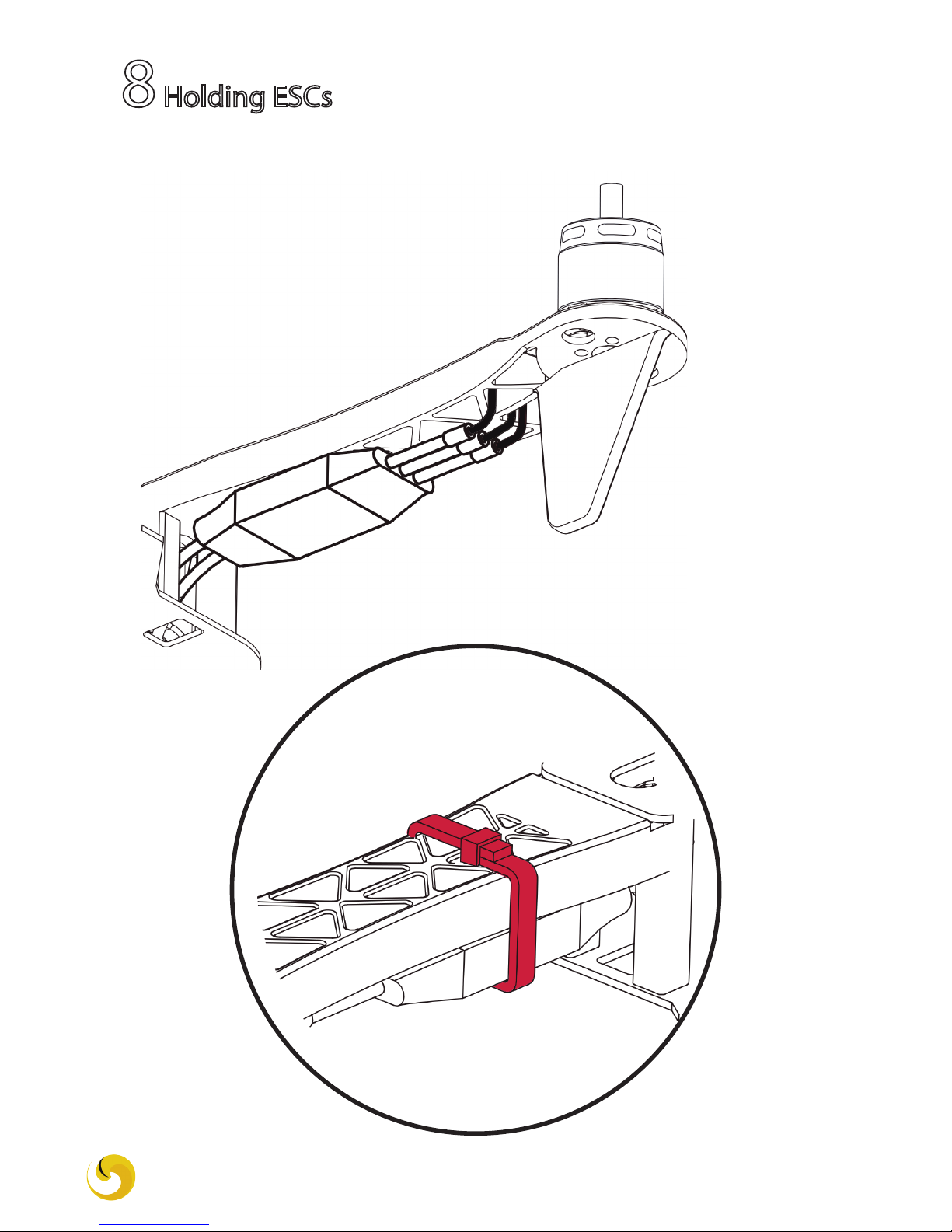
Tie the ESCs using cable ties.
8Holding ESCs
ERLE-COPTER DIY UBUNTU CORE DRONE KIT 16
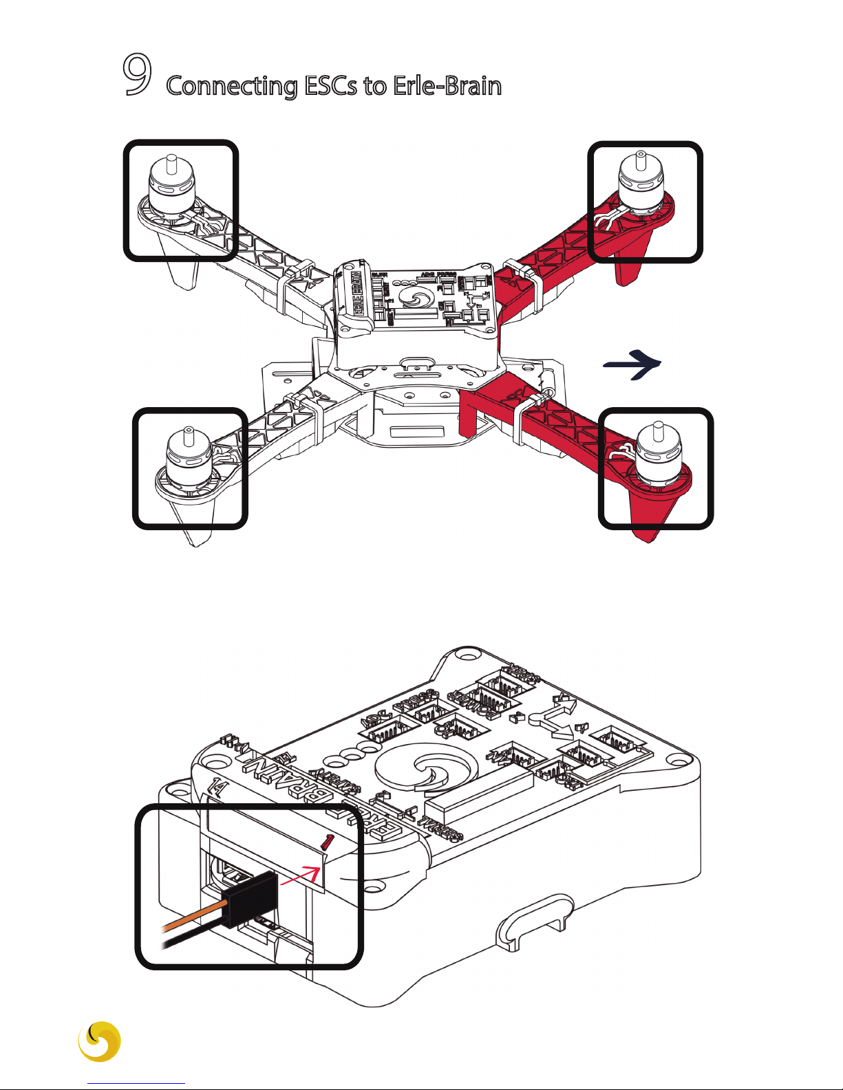
9 Connecting ESCs to Erle-Brain
FRONT
1
2 3
4
Start with motor 1: attach the connector to the rst channel of the rail.
The white wire must be at the top. Do the same with the other 3 ESCs
following the order described above.
ERLE-COPTER DIY UBUNTU CORE DRONE KIT 17
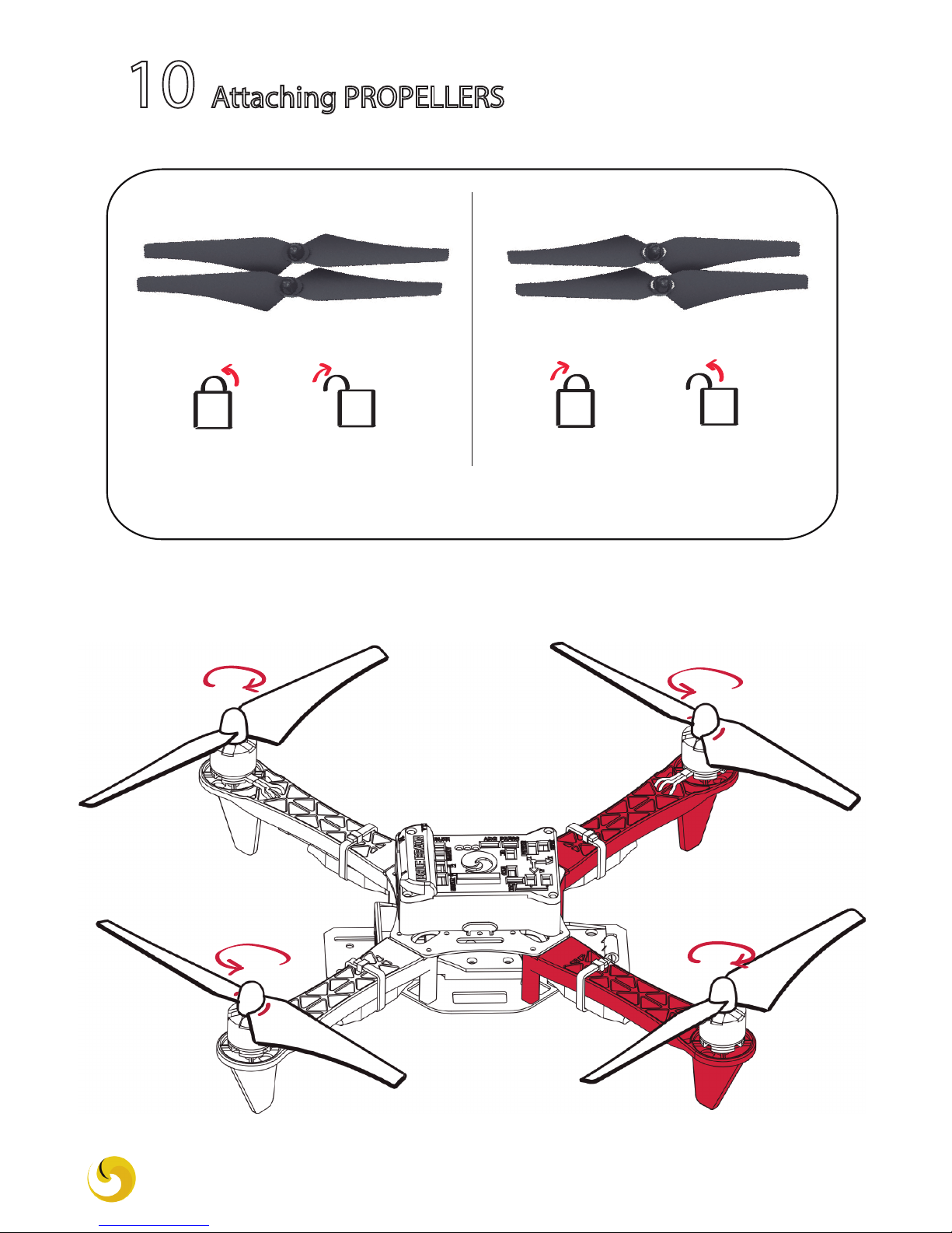
10 Attaching PROPELLERS
Lock Unlock Lock Unlock
COUNTER-CLOCKWISE CLOCKWISE
1
2 3
4
MOTORS 1 and 2 MOTORS 3 and 4
ERLE-COPTER DIY UBUNTU CORE DRONE KIT 18
NOTE: As you can see in the image, the clockwise propellers have a white detail
on the top to distinguish them.

IF YOU HAVE BOUGHT ANY
ADDITIONAL COMPONENT
...
ERLE-COPTER DIY UBUNTU CORE DRONE KIT 19
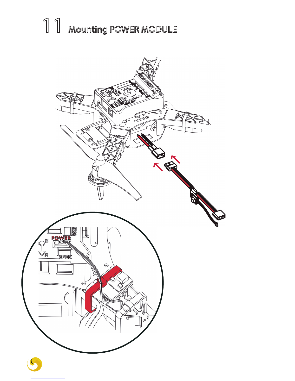
11 Mounting POWER MODULE
1. Connect the power module to the frame´s XT-60 connector:
2. Fasten the power module
to the front left arm with a
cable tie and connect it to
Erle-Brain: POWER
ERLE-COPTER DIY UBUNTU CORE DRONE KIT 20
Other manuals for ERLE-COPTER
1
Table of contents


