1A - Generalità
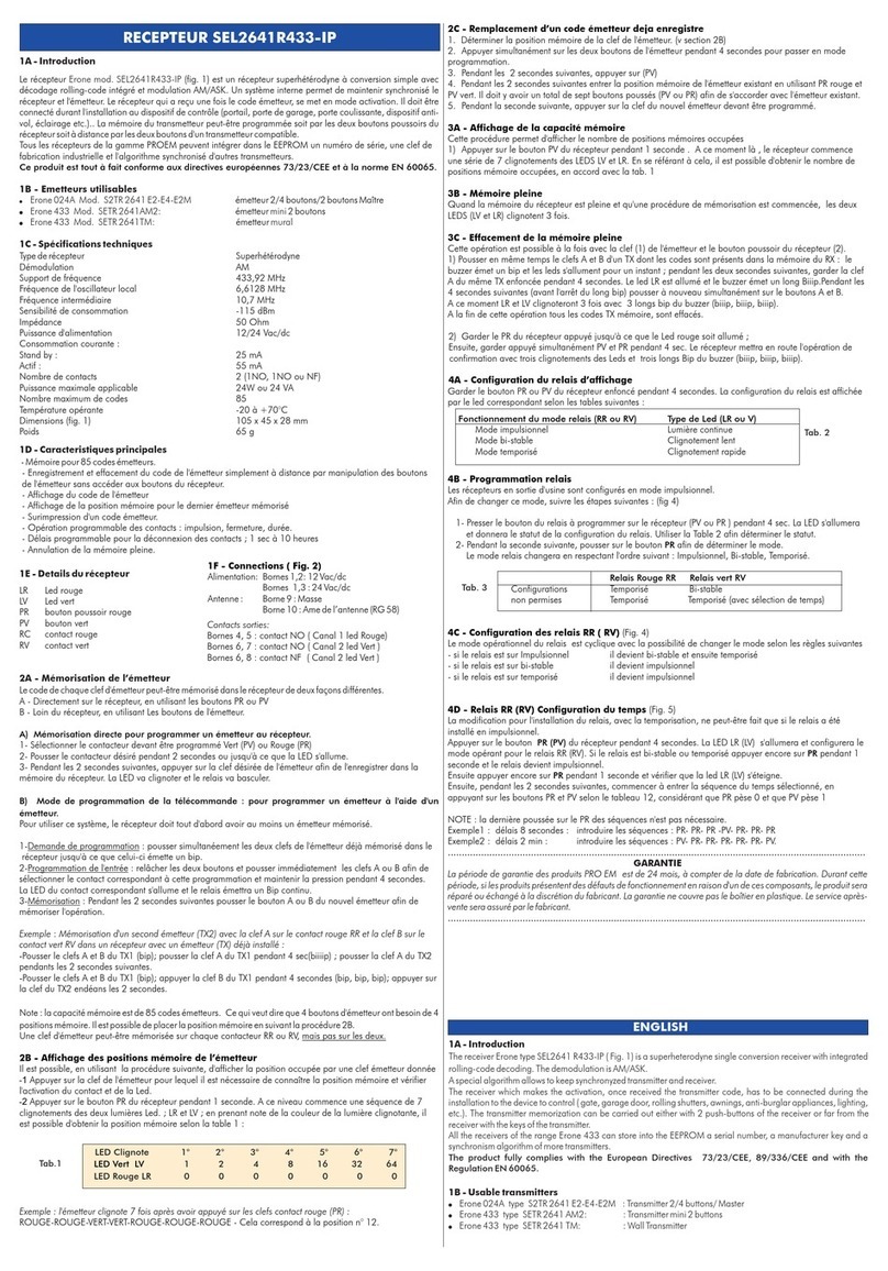
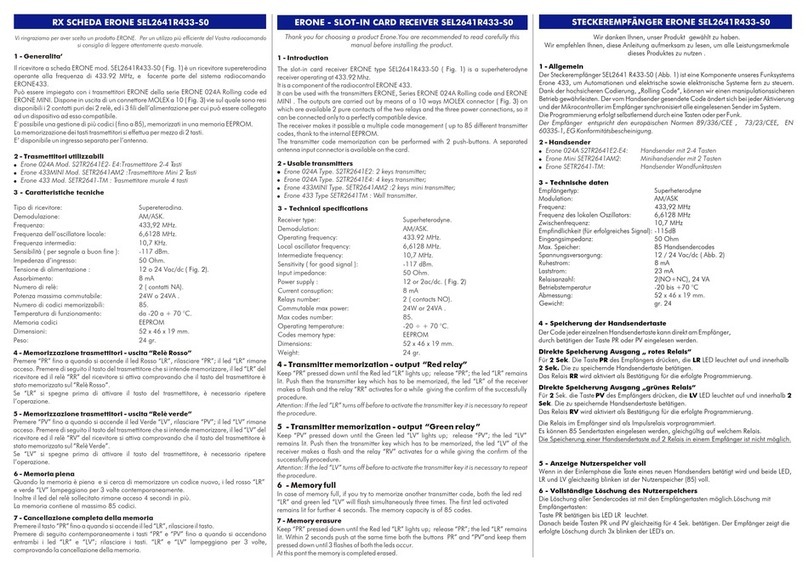
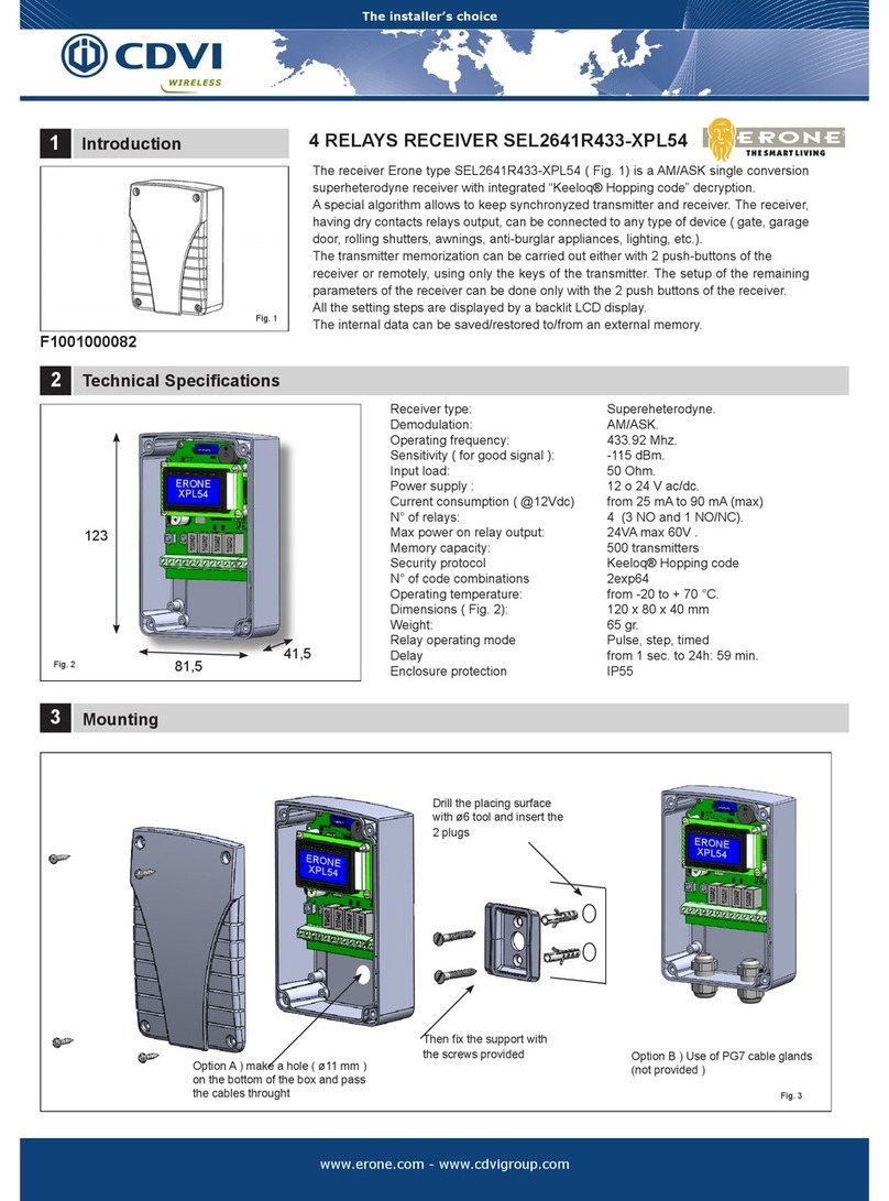
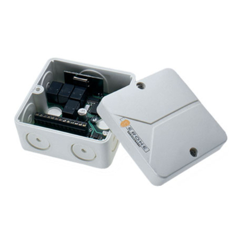
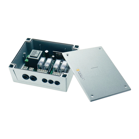
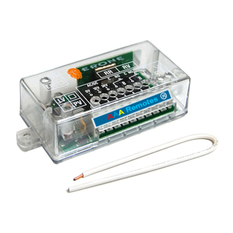
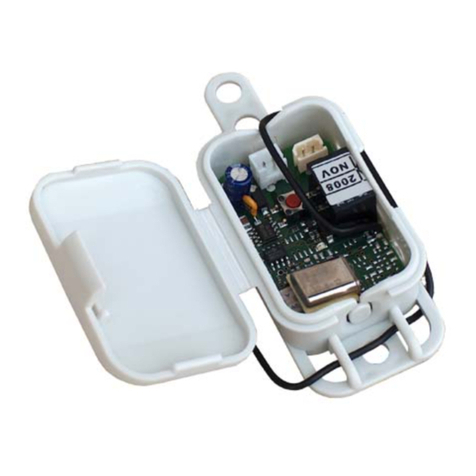
Il ricevitore mod. SEL2641 R433I è un ricevitore supereterodina a singola
conversione, con decodifica integrata del tipo rolling code.
Un sistema interno permette di mantenere sempre sincronizzati ricevitore e
trasmettitore. Il ricevitore, disponendo in uscita di contatti puri, può essere
collegato ad un qualsiasi tipo di meccanismo ( cancello, porta di garage,
serrande, tapparelle, tende, centrale antifurto, illuminazione, ecc.).
La programmazione si effettua in autoapprendimento per mezzo di 2 tasti.
Tutti i ricevitori della serie Erone sono in grado di apprendere e conservare in
EEPROM il codice di serie e l’algoritmo di sincronizzazione di più trasmettitori.
Il prodotto è conforme alle direttive Europee 73/23/CEE, 89/336/CEE ed
alla normativa EN 60065.
1B - Trasmettitori impiegabili
!Erone 024A Mod. S2TR 2641 E2-E4-E2M :Trasmettitore 2/4 Tasti/ Master
!Erone 433 Mod. SETR 2641 AM2: Trasmettitore mini 2 Tasti
!Erone 433 Mod. SETR 2641 TM: Trasmettitore murale
1C - Caratteristiche tecniche
Tipo di ricevitore: Supereterodina.
Demodulazione: AM/ASK.
Frequenza: 433.92 MHz.
Frequenza dell’oscillatore locale: 6,6128 MHz.
Frequenza intermedia: 10,7 MHz.
Sensibilità ( per segnale a buon fine ): -115 dBm.
Impedenza d’ingresso: 50 Ohm.
Tensione di alimentazione : 12 o 24 V ac/dc.
Assorbimento: a riposo: 25 mA
a carico: 55 mA
Numero di relè: 2 (1NA e 1NA o NC).
Potenza massima commutabile: 24W o 24VA .
Numero di codici memorizzabili: 85.
Temperatura di funzionamento: da -20 a + 70 °C.
Dimensioni: 105 x 45 x 28 mm.
Peso: 65 gr.
1D - Funzionalità principali
!85 tasti trasmettitore memorizzabili
!Visualizzazione N° utenti in memoria
!Visualizzazione posizione in memoria dell'ultimo codice Tx ricevuto
!Sovrascrittura codice di Tx già presente in memoria
!Cancellazione completa della memoria.
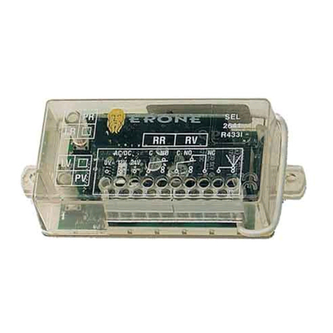
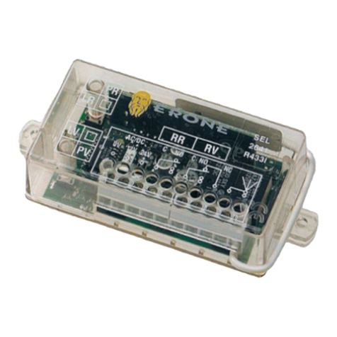
1E - Legenda Ricevitore ( Fig. 1)
LR: Led Rosso LV: Led Verde
PR: Pulsante Rosso PV: Pulsante Verde
RR: Relè Rosso RV: Relè Verde
1F - Connessioni
- Alimentazione : morsetti 1 e 2 : 12 Vac/dc
morsetti 1 e 3 : 24 Vac/dc
- Antenna : morsetto 9 : calza
morsetto 10 : filo.
- Uscite relè : morsetti 4 e 5 : contatto n.a. (relè rosso)
morsetti6 e 7: contatto n.a. (relè verde)
morsetti6 e 8: contatto n.c. (relè verde).
2A - Memorizzazione codice dei trasmettitori
Uscita “Relè Rosso”
1) Premere il tasto del PR del ricevitore : il led LR si accende; rilasciare PR.
2) Premere il tasto del trasmettitore che si intende memorizzare : il led LR si spegne
; il relè RR scatta a conferma dell'avvenuta memorizzazione.
3) Premere il tasto del Tx e verificare l'attivazione del relè rosso RR.
A partire da questo istante ad ogni attivazione il led rosso "LR" si accende mentre
contemporaneamente il led verde "LV" lampeggia.
Uscita “Relè Verde”
1) Premere il tasto del PV del ricevitore : il led LV si accende; rilasciare PV.
2) Premere il tasto del trasmettitore che si intende memorizzare : il led LV si spegne
; il relè RV scatta a conferma dell'avvenuta memorizzazione.
3) Premere il tasto del Tx e verificare l'attivazione del relè verde RV.
A partire da questo istante ad ogni attivazione il led verde "LV" si accende mentre
contemporaneamente il led rosso "LR" lampeggia.
NOTA : La capacità di memoria del ricevitore è di 85 tasti trasmettitore.
Ciò significa che un trasmettitore con 4 tasti occupa 4 posizioni di memoria.
Di ogni tasto trasmettitore è possibile visualizzare la posizione di memoria
tramite la procedura descritta al punto 2B.
Un tasto trasmettitore può essere memorizzato indifferentemente sul relè rosso
RR o sul relè verde RV ma non su entrambi.
2B - Visualizzazione posizione di memoria dei trasmettitori
1) Attivare il tasto trasmettitore di cui si vuole conoscere la posizione di memoria
e verificare l'accensione del led corrispondente e l'attivazione del relè.
2) Premere il tasto PR del ricevitore per1 secondo.
A questo punto il ricevitore comincia una sequenza di 7 accensioni dei led LR ed
LV: annotando la sequenza è possibile risalire alla posizione di memoria in base
alla tabella seguente:
Led acceso 1 2 3 4 5 6 7
Peso colore verde 1 2 4 8 16 32 64
Peso colore rosso 0 0 0 0 0 0 0
Esempio :
Sequenza di accensione led : LR, LR, LV, LV, LR, LR, LR.
Il numero ottenuto sarà: 0 + 0 + 4 + 8 + 0 + 0 + 0 = 12
Perciò il trasmettitore si trova nella posizione 12 di memoria.
2C - Sovrascrittura codici TX già presenti in memoria
1) Premere PR o PV del ricevitore per 4 sec. , il relativo led si accende.
2) Entro 2 sec. premere PV per 1 sec e verificare lo spegnimento del led
3) Entro 2 sec dallo spegnimento del led., iniziare ad introdurre la sequenza
indicante la posizione da sovrascrivere. ( ved. tab.1 ).
4) Al termine della sequenza verificare l'accensione del led ( verde o rosso a
seconda del relè attivato dal codice da sovrascrivere )
5) Entro 4 sec. premere il tasto del nuovo TX da memorizzare.
3A - Visualizzazione spazio di memoria
1) Premere il tasto PV del ricevitore per 1 secondo.
A questo punto il ricevitore comincia la sequenza di 7 accensioni dei led LR ed LV:
in base ad essa è possibile risalire al numero di celle occupate di memoria
secondo la tabella 1.
3B - Memoria piena
Se, al termine del punto 2 della procedura di memorizzazione, premendo il tasto
di un trasmettitore da memorizzare, lampeggiano contemporaneamente
entrambi i led LR ed LV, significa che lo spazio di memoria è esaurito.
3C - Cancellazione completa della memoria
1) Premere il tasto PR del ricevitore fino a che si accende il led rosso LR;
2) rilasciare e successivamente premere e mantenere premuti entrambi i tasti del
ricevitore PR e PV per 4 sec. fino a quando il ricevitore segnala l'avvenuta
cancellazione totale con 3 lampeggi dei 2 led.
RICEVITORE SEL2641R433-I
Tab. 1
RR RV
1098
7
6
5
4
3
21
+- +
12V0V
AC/DC
24V
C NA C NA NC
PR
RVRR
LR
PV
LV
SEL 2641
R433-I
Costruito da ELPRO INNOTEK S.p.A.
Via Piave, 23 - I-31020 S.Pietro di Feletto (TV) - ITALIA
Tel. 0438.450879 - Fax. 0438.457126
Numero Verde: 800.53.46.46
GARANZIA
La garanzia è di 24 mesi dalla data di fabbricazione apposta all’interno.
Durante tale periodo, se l’apparecchiatura non funziona correttamente, a causa
di un componente difettoso, essa verrà riparata o sostituita a discrezione del
fabbricante. La garanzia non copre l’integrità del contenitore plastico.
La garanzia viene prestata presso la sede del fabbricante.
Fig. 1
1A - Introduction
The receiver type SEL2641 R433I is a superheterodyne single conversion receiver
with integrated rolling-code decoding. The demodulation is AM/ASK.
A special algorithm allows to keep synchronyzed transmitter and receiver.
The receiver which makes the activation, once received the transmitter code, has to
be connected during the installation to the device to control ( gate, garage door,
rolling shutters, awnings, anti-burglar appliances, lighting, etc.).
The transmitter memorization can be carried out with 2 push-buttons.
All the receivers of the range Erone 433 can store into the EEPROM a serial
number, a manufacturer key and a synchronism algorithm of more transmitters.
The product fully complies with the European Directives 73/23/CEE,
89/336/CEE and with the Regulation EN 60065.
1B - Usable transmitters
!Erone 024A type S2TR 2641 E2-E4-E2M : Transmitter 2/4 buttons/ Master
!Erone 433 type SETR 2641 AM2: : Transmitter mini 2 buttons
!Erone 433 type SETR 2641 TM: : Wall Transmitter
1C - Technical specifications
Receiver type: Superheterodyne.
Demodulation: AM/ASK.
Operating frequency: 433,92 MHz.
Local oscillator frequency: 6,6128 MHz.
Intermediate frequency: 10,7 MHz.
Sensitivity (for good signal): -115 dBm.
Input impedance: 50 Ohm.
Supply voltage : 12 or 24 V ac/dc.
Current consumption: at rest: 25 mA
with relay excited: 55 mA
Number of relays: 2 (1NO, 1NO or NC).
Commutable max power: 24W or 24VA .
Max codes number: 85.
Operating temperature: from -20 to + 70 °C.
Dimensions: 105 x 45 x 28 mm.
Weight: 65 gr.
1D - Main features
!Memory for 85 transmitter keys
!Display of the transmitter key number
!Display of the memory position for the last memorized transmitter
!Overwrite of a transmitter code
!Full memory cancellation.
1E - Receiver detail ( Fig. 1)
LR: Red Led LV: Green led
PR: Red push-button PV: Green push-button
RR: Red relay RV: Green relay
1F - Connections
- Power supply : terminals 1, 2 : 12 Vac/dc
terminals 1, 3 : 24 Vac/dc
- Aerial : terminal 9 : shield
terminal 10 : net.
- Relay outputs : terminals 4, 5 : NO contact ( red relay)
terminals 6, 7: NO contact ( green relay)
terminals 6, 8: NC contact ( green relay)
2A - Transmitter memorizing
“Red relay” output
1) Keep the button PR of the receiver pressed down until the led LR remains lit, then
release the button PR.
2) Press the key of the transmitter which is to be memorized : the led LR will turn off
and the relay RR will excite for a while.
3) Press the key of the transmitter again and verify the activation of the relay RR the
red led LR lit and the flash of the led LV.
At each activation, and for all the transmission time, the red led LR will turn on ,the
green led LV will flash and the relay RR remains excited.
“Green relay” output
1) Keep the button PV of the receiver pressed down until the led LV remains lit, then
release the button PV.
2) Press the key of the transmitter which is to be memorized : the led LV will turn off
and the relay RV will excite for a while.
3) Press the key of the transmitter again and verify the activation of the relay RV
thegreen led LV lit and the flash of the led LR.
NOTE : The memory capacity is of 85 transmitter keys. That means that a 4 keys
transmitter needs 4 memory positions.
It is possible to display the memory position by following the procedure 2B
A transmitter key can be memorized on each relay RR or RV but not on both.
2B - Transmitter memory position display
1) Activate the transmitter to display and verify the which is the led that turns on
and the relay which excites.
2) Keep the button PR pressed down for 1 sec.
At this point a sequence of 7 flashes of the led LR and LV commences : by taking a
note of the colors it is possible to get the memory position, according to the
following table:
Led lit 1 2 3 4 5 6 7
Green led weight 1 2 4 8 16 32 64
Red led weight 0 0 0 0 0 0 0
Example :
Sequence : LR, LR, LV, LV, LR, LR, LR.
Number : 0 + 0 + 4 + 8 + 0 + 0 + 0 = 12
So the transmitter is located on the 12th memory position.
2C - Transmitter codes overwrite
1) Keep the button PR or PV of the receiver pressed down for 4 sec. until the
corresponding led remains lit, then release the button.
2) Within 2 sec. press down PV for 1 sec : the led lit will turn off.
3) Within 2 sec , begin to push PR or PV according the sequence which represents
the position to overwrite ( see. tab.1 ).
4) At the end of the sequence the led LV or LR will turn on ( depending upon the
memory information)
5) Within 4 sec. activate the key of the new transmitter which is to be memorized.
3A - Memory space display
1) Keep the button PV of the receiver pressed down for 1 sec.
At this point a sequence of 7 flashes of the led LR and LV commences : by taking a
note of the colors it is possible to get the number of the memory location already
occupied , following the above tab.1
3B - Memory full
When the receiver memory is full, if ( at the end of item 2 of the memorizing
procedure ) the key of a new transmitter is activated, both the leds LV and LR flash
3 times.
3C - Cancelling the entire memory
1) Keep the button PR of the receiver pressed down until the led LR remains lit.
2) Release the button PR and within 1 sec. keep the buttons PR and PV pressed
down simultaneously for 4 sec. until a sequence of 3 flashes of the led LR and LV
commences.
At the end the entire memory has been cancelled.
RECEIVER SEL2641R433-I
Tab. 1
RR RV
1098
7
6
5
4
3
21
+- +
12V0V
AC/DC
24V
C NA C NA NC
PR
RVRR
LR
PV
LV
SEL 2641
R433-I
Manufactured by CDVI Wireless S.p.A.
Via Piave, 23 - 31020 S.Pietro di Feletto (TV) - ITALY
Tel. +39-0438-450860 - Fax. +39-0438-455628
Web: www.erone.com
GUARANTEE
The guarantee period of the product is 24 months, beginning from the
manufacturer date. During this period, if the product does not work correctly, due
to a defective component, the product will be repaired or substituted at the
discretion of the producer. The guarantee does not cover the plastic container
integrity. After-sale service is supplied at the producer's factory.
Fig. 1
At each activation, and for all the transmission time, the green led LV will turn on
,the red led LR will flash and the relay RV remains excited.


