manuals.online logo
Brands
  1. Home
  2. •
  3. Brands
  4. •
  5. Erone
  6. •
  7. Receiver
  8. •
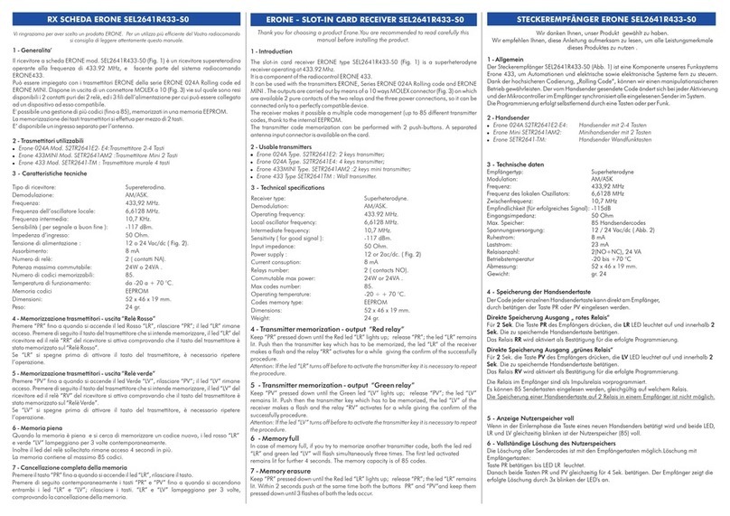
  9. Erone SEL2641R433-TW User manual

Erone SEL2641R433-TW User manual

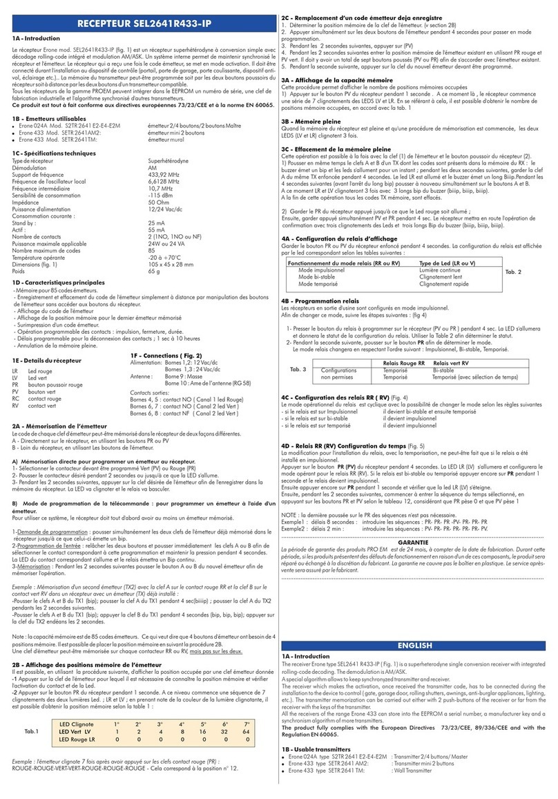
1 - Introduction
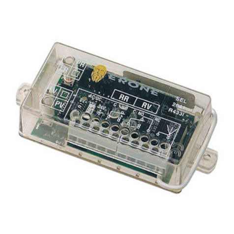
The two-ways system ERONE is composed by the transmitter type S2TR2641TW and by the
receiver type SEL2641R433-TW.
Both the appliances are equipped with a rx-transmitter device which allows to realize an half-
duplex transmission , with a command signal sent by the transmitter and by the acknoledge signal
sent by the receiver.
6 - Receiver SEL2641R433-TW functionalities
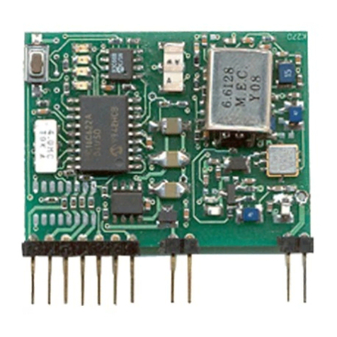
The receiver is a superheterodyne-type with single conversion and low noise input amplifier
and Saw filter. It is equipped with 2 relays, 2 inputs for the managing of the feedback and a
RFpower transmitter module to send back the answer to the transmitter.
The power supply is 12/24 Vac/dc.
The relays have pulse, step and delayed operating mode, with separated programmable delay
The two auxiliary inputs can be used to connect the signals coming from an antiburglar system.
Each time a signal, coming from the transmitter has received, the receiver doesn’t activate the
relays but sends back an acknoledge signal to the transmitter.
Once received this signal, the transmitter sends the same information again.
Once received this next signal, the receiver activates the relays.
In this way there is the security that both the devices are able to communicate successfully.
After the relay activation, the receiver sends again a signal with the status info about the relays
or the auxiliary inputs depending upon the jumper J1 or J2 position.
If the jumpers are open, this last signal is sent after 4 seconds, to allow the reception of
feedback communication by a connected antiburglar system.
2 - TX Technical specifications
N° of keys:....................................................................2
Power supply:................................................................12 Vdc
Battery: ........................................................................23A - L1028
Carrier frequency: .........................................................433,92 MHz
Modulation:..................................................................AM/ASK
®
Security system protocol:................................................Keeloq Hopping Code
Range ( in open space ):................................................70 m
Erp power :...................................................................250 µW
Sensitivity receiver circuit:...............................................-103 dBm
Dimensions (mm): ........................................................83 x 48 x 16
Weight: ........................................................................40 gr
Max transmission time ...................................................1 sec.
Max delay of RX signal reception ....................................5 sec. 7 - Receiver layout
4 - RX main features
!Memory for 21 transmitter keys;
!Display of the transmitter key number;
!Display of the memory position for the last memorized transmitter;
!Overwrite of a transmitter code;
!Programmable operation of the relays: pulsing, latching and timed;
!Programmable delay of release for the relays from 1 sec. to 10 hours;
!Full memory erasure.
!2 auxiliary inputs for feedback signals of a antiburglar system
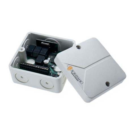
8 - Connections ( Fig. 3)
Power supply : terminal boards 4, 5 : 12 Vac/dc
terminal boards 4, 6 : 24 Vac/dc
Output relay RR : terminal boards 8, 7 : contact NO (relay RR)
terminal boards 8, 9 : contact NC (relay RR)
terminal boards 11, 10: contact NO relay RV)
terminal boards 11, 12: contact NC relay RV)
Auxiliary inputs: terminal boards 1, 3 : contact N° 1- NO
terminal boards 2, 3 : contact N° 2- NO
9 - Transmitter memorisation
Each transmitter key can be memorised into the receiver by using the push-buttons PR or PV
according to the following procedure.
1) Select the relay to be programmed Green (RV) or Red (RR)
2) Push desired relay key PR or PV for 2 seconds or until LED LR (LV) comes on
3) Within 2 seconds press desired transmitter key to store in receiver memory.
LED light should blink and relay should cycle.
NOTE 1: The receiver is set-in-factory to operate with the relays in pulse mode.
See paragraph 17 to change the mode. See paragraph 18 to set the delay time.
3 - RX Technical specifications
Receiver type: ...............................................................Superheterodyne
Carrier frequency: ........................................................433,92 MHz
Local oscillator frequency:..............................................6,6128 MHz
Modulation:..................................................................AM / ASK
Power supply:................................................................12/24 Vac/dc
®
Security system protocol:................................................ Keeloq Hopping Code
Erp power ( RF power module ): .....................................10 mW
Sensitivity:.....................................................................-115 dBm
Outputs RX : ...................................................................2 ( NO / NO-NC)
Operating temperaturs: .................................................-10°C / +70 °C
IP grade of the enclosure: .............................................IP2X
Dimensions (mm): ........................................................120 x 60 x 25
Weight: ........................................................................110 gr
Auxiliary inputs..............................................................2
Button A
Button B
bicolor LED
Key holder ring
Battery door : slide to open
Battery
+_
23A
Polarity
5 - Transmitter S2TR2641TW functionalities
The transmitter has two channels with Keeloq Hopping code security system and operating
frequency of 433,92 MHz. The appliance integrates an superheterodyne receiver which allows
to detect the receiver answer from about 40 / 40 meters. The transmitters displays the receiver
status by means of a two-colours led and a buzzer. The transmission is shown by the blinking of
Fig. 1
SEL2641R433-TW
S2TR2641TW
Fig. 2
ERONE Transmitter with feedback
the led which becomes red or green acconding to the activated key
The transmission lasts for 1 second ( even if the key hasn’t been released ).
After the blinking of the led the buzzer gives the information about the relay: 1 beep means
“Open contact” , 2 beeps mean “Close contact”.
Within 5 seconds the led switch on again for 2 seconds with RED colour, if the contact is open
and in GREEN colour if the contact is closed. If the external input of the receiver has been
enabled the buzzer will give the status of the relays too: 1 beep if the input is open, 2 beeps if the
input is closed.
Event Nr. Direction Event type
1 TX --> RX 1st Transmission
2 RX --> TX Acknoledge
3 TX --> RX 2nd Transmission
4 RX Relay activation
5 RX --> TX Status relay / inputs
6 TX LED + Buzzer activ.
Two way transmission protocol
12345678910 11 12
0
+12
+24
~
~
PR PV
J1 J2
LR LV
RR RV
Fig. 3
Power
L1 L2
I1
I2
C
NOTE 2 : The memory capacity is of 21 transmitter keys. This means that a 2 key transmitter
needs 2 memory positions. It is possible to display the memory position by following the
procedure 10.
A transmitter key can be memorized on each relay RR or RV but not on both.
10 - Display of the transmitter memory position
With this procedure it is possible to display the position occupied by a given transmitter key.
1) Push the transmitter key for which you need to know the memory position and verify the
activation of the relay and the led.
2) Push the button PR of the receiver for 1 second.
At this point begins a sequence of 7 lightings of the two led LR and LV: by taking a note of what
color light blinks, it is possible to get the memory position, according to the table 1:
Led flash 1 2 3 4 5 6 7
Green LED 1 2 4 8 16 32 64
Red LED 0 0 0 0 0 0 0
Example:
Transmitter blinks the following seven times after pushing the red relay (PR) key:
RED - RED - GREEN - GREEN - RED - RED - RED
This corresponds to the 12th position.
11 - Overwrite of an already stored Transmitter code
1 - Determine transmitter key memory position ( see paragraph 10 )
2 - Press corresponding relay programming key PR or PV on receiver for 4 seconds.
3 - Within 2 seconds press PV : the led switches off.
4 - Within 2 seconds enter the transmitter memory position of existing transmitter by using (
PR red ) and ( PV green) accordingly Tab. 1. There must be a total combination of seven
button pushed ( PV or PR) to match the memory position of existing transmitter.
5 - Within 1 second press the new transmitter key to be programmed.
The previous transmitter key will be removed and replaced by the key pressed in step 5.
12 - Memory capacity display
This procedure allows to display the number of occupied memory positions.
1) Push the button PV of the receiver for 1 second.
At this point the receiver begins a sequence of 7 lightings of the leds LR and LV. Referring to that it
is possible to obtain the number of the occupied memory positions, according to tab.1
13 - Memory full
When the receiver memory is full and a memorization procedure is started, both the leds LV and
LR blink 3 times.
14 - Total memory erasure
1) Keep on pushed PR of the receiver until the red led LR is turned on.
2) Keep on pushed simultaneously PV and PR for 4 sec. The receiver will give the operation
confirmation with 3 blinks of the leds LV and LR.
15 - Relay configuration display
Keep on pushed PR (or PV) of the receiver for 4 sec. The current configuration of the relay is
displayed by the corresponding led, according to table 2 :
16 - Relay programming
The relays can be programmed in all the 3 modes ( pulse, step or delayed), but the following
combinations :
Not allowed configurations
Red relay (RR) Green Relay (RV)
Step Delayed
Delayed Delayed ( with different delay time )
17 - Relay RR (RV) configuration - (Fig. 4)
The operating mode of the relay is cyclic. See below to change the mode
-If the relay is set as pulse: it becomes latching and after timed;
-If the relay is set as latching: it becomes pulse;
-If the relay is set as timed: it becomes pulse.
Operating mode ( RR or RV )
Pulse mode Continuous light
Step mode Slow blinking
Delayed mode Fast blinking
Led light type (LR or LV)
Fig. 5
1
1
1
PR
PV
PR
PR
PR / PV PR
18 - Relay RR ( RV) timing settings -( Fig. 5)
The time settings of the delayed relay can be done only if the relay has been previously set as
pulse.
Push the button PR (PV) of the receiver for 4 sec.;the led LR (LV) will turn on and will display the
present operating mode of the relay RR (RV). If the led blinks slow or fast push again PR for 1
sec. and the relay will be set as pulse. Then push PR for 1 sec. and the led LR (LV) switches off.
Then, within 2 seconds, begin to set the selected relay time, by pushing on the buttons PR and
PV according to Table 4 and considering that PR has weight of "0" while PV has weight "1".
NOTE: The last pressures on PR of the sequence are not necessaries.
Example 1: 8 sec. delay : input the sequence : PR - PR - PR - PV - PR - PR - PR.
Example 2: 2 min delay.: input the sequence : PV - PR - PR - PR - PR - PR - PV.
Fig. 4
1
1
1
PR / PV PR
Pulse
Step
Delayed
Step
Pulse
Pulse
PR
PR
19 - Jumper J1 and J2 settings
The jumper J1 and J2 allow to set the operating mode of the receiver when it replies to the
transmitter.
Once received the second signal by the transmitter, the receiver sends back the “Status signal”
to communicate the transmitter the status of the relays or the auxiliary inputs.
The information sent contains the status of the relays ( which can be in step or pulse/delayed
mode ) or the inputs which can be open or closed.
The message is different depending upon the jumper J1 and J2.
Before to send the message, the receiver does a test on the status of the relays RR and RV and
the inputs connected at the terminals 1,2, 3)
With the information received by the receiver, the transmitter switch on the led green or red and
the buzzer. Refer to table 5 to know the status of the relays / inputs by the colour of the led and
the bip of the buzzer.
NOTE : When the receiver sends the logic level of the auxiliary inputs ( jumper J1, J2 OPEN),
the message is sent to the transmitter with a delay of 4 sec. to allow the security appliances
connected to change their status.The status of the inputs ( I1-C and I2-C ) is monitored by the 2
led L1 and L2.
Logic level of input at terminal 1-3
Logic level of input at terminal 2-3
Status relay RR
Status relay RV
Current configuration
Final configuration
IS-RTWERUK Rev
. 3 del 13.06.2017
Manufactured by CDVI Wireless Spa
Via Piave, 23 - 31020
San Pietro di Feletto (TV) - Italy
Tel: +39.0438.450860 - Fax: +39.0438.455628
e-mail:
Web: www.erone.com
[email protected]
T H E S M A R T L I V I N G
The guarantee period of the product is 24 months, beginning from the manufacturer date.
During this period, if the product does not work correctly, due to a defective component, the
product will be repaired or substituted at the discretion of the producer. The guarantee does not
cover the plastic container integrity. After-sale service is supplied at the producer's factory.
GUARANTEE
Tab 4
Pressioni tasti / Button act /
Tastenbetatingung/ 1° 2° 3° 4° 5° 6° 7°
Presion botones
sec/sec./sek/seg. 1 2 4 8 16 R R
sec/sec./sek/seg. 10 20 40 80 160 V R
Min/min/min/min 2 4 8 16 32 R V
Min/min/min/min 20 40 80 160 320 V V
Tab. 1
Tab. 2
Tab. 3
J1
J2
Jumper
Open
Jumper
Closed
OPEN
CLOSED
BUZZER TX LED TX
1 BEEP
2 BEEP
RED
GREEN
OPEN
CLOSED
BUZZER TX LED TX
1 BEEP
2 BEEP
RED
GREEN
PULSE
STEP
BUZZER TX LED TX
2 BEEP
2 ( on )BEEP
GREEN
GREEN
BUZZER TX LED TX
2 BEEP
2 ( on )BEEP
GREEN
GREEN
Tab. 5
PULSE
STEP
1 ( off )BEEP RED
1 ( off )BEEP RED
Hereby, CDVI Wireless Spa, declares that the radio equipment type ,
is in compliance with directive 2014/53/EU. The full text of the EU
declaration of conformity is available at the following internet address: www.erone.com.
SEL2641R433-TW
S2TR2641TW

This manual suits for next models

1

Other Erone Receiver manuals

Erone SEL2641 R433-IP User manual

Erone

Erone SEL2641 R433-IP User manual

Erone SEL2641R433-C5P User manual

Erone

Erone SEL2641R433-C5P User manual

Erone SEL128R433-NN User manual

Erone

Erone SEL128R433-NN User manual

Erone SEL2641R433-S7 User manual

Erone

Erone SEL2641R433-S7 User manual

Erone SELCD4A User manual

Erone

Erone SELCD4A User manual

Erone SEL2641R433-IP User manual

Erone

Erone SEL2641R433-IP User manual

Erone SEL2641R433C2V Technical specifications

Erone

Erone SEL2641R433C2V Technical specifications

Erone CDVI ERMU Technical specifications

Erone

Erone CDVI ERMU Technical specifications

Erone SEL2641R433-I User manual

Erone

Erone SEL2641R433-I User manual

Erone SEL39R433-M1 User manual

Erone

Erone SEL39R433-M1 User manual

Erone SEL2641R433-C4R Technical specifications

Erone

Erone SEL2641R433-C4R Technical specifications

Erone EL2641 R433-IP User manual

Erone

Erone EL2641 R433-IP User manual

Erone SEL2641R433-I User manual

Erone

Erone SEL2641R433-I User manual

Erone SEL2641 R433-Z4 User manual

Erone

Erone SEL2641 R433-Z4 User manual

Erone SEL2641R433-BD4 Technical specifications

Erone

Erone SEL2641R433-BD4 Technical specifications

Erone 433 Z2 Series User manual

Erone

Erone 433 Z2 Series User manual

Erone SEL2641R433-OC4 User manual

Erone

Erone SEL2641R433-OC4 User manual

Erone SEL 39 R27-M1 User manual

Erone

Erone SEL 39 R27-M1 User manual

Erone SEL2641R433C4 Technical specifications

Erone

Erone SEL2641R433C4 Technical specifications

Erone SEL2641R433-S0 User manual

Erone

Erone SEL2641R433-S0 User manual

Erone SEL2641R433-S1 User manual

Erone

Erone SEL2641R433-S1 User manual

Erone SEL2641R433-PP4 User manual

Erone

Erone SEL2641R433-PP4 User manual

Erone SEL2641 433 Z1 User manual

Erone

Erone SEL2641 433 Z1 User manual

Erone SEL2641R433-S2 User manual

Erone

Erone SEL2641R433-S2 User manual

Popular Receiver manuals by other brands

Integra DTR-4.5 instruction manual

Integra

Integra DTR-4.5 instruction manual

JVC KW-X850BT quick start guide

JVC

JVC KW-X850BT quick start guide

Vega R-662A PRO PLUS owner's manual

Vega

Vega R-662A PRO PLUS owner's manual

Yamaha RX-V575 Easy setup guide

Yamaha

Yamaha RX-V575 Easy setup guide

Telex MCS2000 Application guide

Telex

Telex MCS2000 Application guide

Triax DVB 75SI user guide

Triax

Triax DVB 75SI user guide

Cambridge Audio Azur 351R user manual

Cambridge Audio

Cambridge Audio Azur 351R user manual

Xantech BDX TT installation instructions

Xantech

Xantech BDX TT installation instructions

Climax Vesta Series installation guide

Climax

Climax Vesta Series installation guide

Daewoo DSD-9251MA Service manual

Daewoo

Daewoo DSD-9251MA Service manual

a-eberle 111.9024.45 operating manual

a-eberle

a-eberle 111.9024.45 operating manual

Yamaha RX-V2400RDS owner's manual

Yamaha

Yamaha RX-V2400RDS owner's manual

NAD T 743 Service manual

NAD

NAD T 743 Service manual

Sherwood RD-8500 operating instructions

Sherwood

Sherwood RD-8500 operating instructions

Sennheiser 500 Series instruction manual

Sennheiser

Sennheiser 500 Series instruction manual

CaryMart 0020105 manual

CaryMart

CaryMart 0020105 manual

Sony STR-DN1000 Service manual

Sony

Sony STR-DN1000 Service manual

Pioneer XV-HTD520 Service manual

Pioneer

Pioneer XV-HTD520 Service manual

manuals.online logo
manuals.online logoBrands
  • About & Mission
  • Contact us
  • Privacy Policy
  • Terms and Conditions

Copyright 2025 Manuals.Online. All Rights Reserved.