Errebi MICRO User manual

MACCHINA DUPLICATRICE
MICRO
MANUALE D´ ISTRUZIONI
KEY CUTTING MACHINE
MICRO
INSTRUCTION MANUAL
MICRO
V-01
KOPIERMASCHINE
MICRO
ANWEISUNGSHANDBUCH
MACHINE A TAILLER LES CLES
MICRO
NOTICE D’UTILISATION


www.errebispa.com 3
MICRO
MACCHINA DUPLICATRICE
MANUALE D´ ISTRUZIONI
ITALIANO
www.errebispa.com 3

4
ITALIANO
MICRO manuale d´ istruzione
1
PRESENTAZIONE E ASPETTI GENERALI
1.1 PREMESSA GENERALE
1.2 TRASPORTO E IMBALLO
1.3 TARGHETTA DI IDENTIFICAZIONE
2
CARATTERISTICHE DELLA MACCHINA
2.1 TERMINOLOGIA DELLA CHIAVE
2.2 PRINCIPALI ELEMENTI DELLA MACCHINA
2.3 DATI TECNICI
2.4 COMPONENTI E PARTI FUNZIONALI
2.4.1 Accessori
2.4.2 Ancoraggio della macchina al bancone
2.4.3 Circuito elettrico
2.4.4 Morsetto a 4 lati
3
OPERATIVITÀ E FUNZIONAMENTO
3.1 REGOLAZIONE DELLA PROFONDITA’
3.2 REGOLAZIONE LATERALE
3.3 DUPLICAZIONE DELLA CHIAVE
3.3.1 Duplicazione di una chiave SENZA FERMO
3.3.2 Duplicazione di una chiave CRUCIFORME
4
MANUTENZIONE
4.1 SOSTITUZIONE DELLA SPAZZOLA
4.2 SOSTITUZIONE DELLA FRESA
4.3 SOSTITUZIONE DEL TASTATORE
4.4 REGOLAZIONE DELLA PROFONDITÀ DEL CARRELLO
4.5 ACCESSO ALL’INTERNO
4.6 SOSTITUZIONE DEI FUSIBILI
4.7 SOSTITUZIONE DELL’INTERRUTTORE DI AZIONAMENTO
4.8 SOSTITUZIONE DEL CIRCUITO ELETTRONICO
4.9 SOSTITUZIONE DELL’INTERRUTTORE DI CIRCUITO
4.10 SOSTITUZIONE E TENSIONAMENTO DELLA CINGHIA
4.11 SOSTITUZIONE DEL MOTORE
5
SICUREZZA
6
SMALTIMENTO DEI RIFIUTI
6.1 IMBALLO
6.2 TRUCIOLO
6.3 MACCHINA
7
ESPLOSO
www.errebispa.com 5
ITALIANO
1
PRESENTAZIONE E ASPETTI GENERALI
1.1 ASPETTI GENERALI
La macchina duplicatriceMICRO è stata progettata nel rispetto delle norme
di sicurezza vigenti nella C.E.E.
La sicurezza del personale addetto alla gestione di questo tipo di macchine
viene raggiunta unicamente attraverso un programma di sicurezza personale
accuratamente progettato, nonché con l’implementazione di un programma
di manutenzione, oltre che con il rispetto delle raccomandazioni per l’uso e
l’adempimento alle norme di sicurezza contemplate dal manuale.
Sebbene l’installazione della macchina non presenti alcuna difcoltà, è pre-
feribile non tentare di installarla, regolarla o manipolarla senza aver letto pre-
viamente il presente manuale.
La macchina esce dai nostri stabilimenti pronta per l’uso e le operazioni di
taratura si renderanno necessarie esclusivamente per gli attrezzi che verran-
no utilizzati.
1.2 TRASPORTO E IMBALLO
La macchina viene consegnata all’interno di una scatola in cartone avente le
seguenti dimensioni:
larghezza = 380 mm; altezza = 260 mm; profondità = 210 mm
Peso macchina (imballaggio incluso) = 7 kg
Al momento dell’apertura della macchina, ispezionarla attentamente per ac-
certarsi che non abbia subito danni durante il trasporto.
Qualora venisse riscontrata un’anomalia di qualsiasi tipo bisognerà avvisare
immediatamente il corriere e non si dovrà svolgere alcuna operazione con
la macchina prima della realizzazione di un’ispezione da parte dell’agente
del corriere.
1.3 TARGHETTA DI IDENTIFICAZIONE
La macchina duplicatrice MICRO è provvista di targhetta di identicazione
recante la specica del numero di serie o matricola della macchina, nome e
indirizzo del fabbricante, marchio CE e anno di fabbricazione.
2
CARATTERISTICHE DELLA MACCHINA
La macchina MICRO è una duplicatrice di ridotte dimensioni, ma di elevata
precisione, destinata alla duplicazione di chiavi piatte per serrature a cilindro,
chiavi di veicoli, chiavi a croce e chiavi speciali.
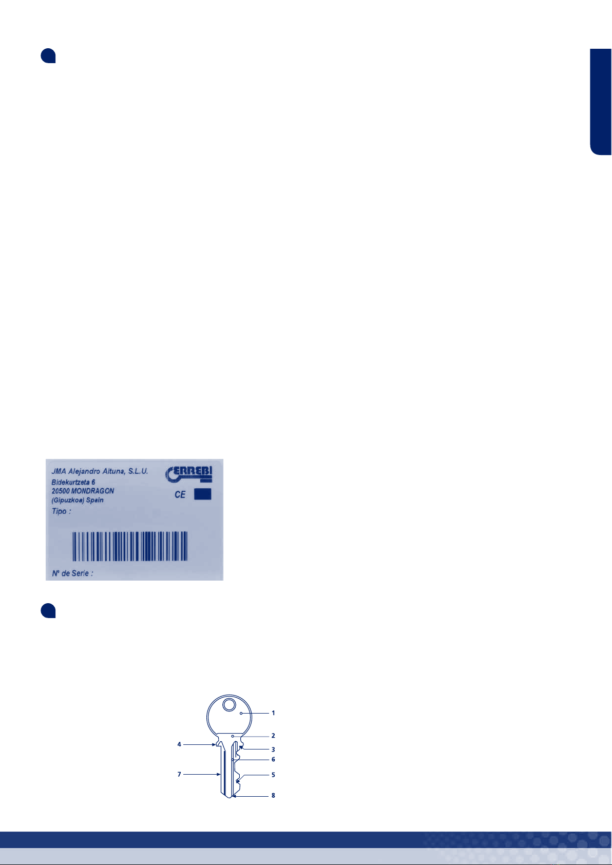
2.1 TERMINOLOGIA DELLA CHIAVE
1. Testa
2. Collo
3. Fermo
4. Fermo superiore
5. Cifratura
6. Canali
7. Dorso
8. Punta
2.2 PRINCIPALI ELEMENTI DELLA MACCHINA
1 - Fresa
2 - Tastatore
3 - Morsetto a 4 lati
4 - Manopola del morsetto
5 - Carrello
6 - Leva di comando del carro
7 - Comando di spostamento del carro
8 - Asta dei calibrini
9 - Comando di regolazione in profondità del tastatore
10 - Spazzola
11 - Interruttore di avviamento
Vedi gura 1
2.3 DATI TECNICI
Alimentazione elettrica: 230V – 50/60Hz (opzionale: 120V – 50/60Hz)
Motore: 230VDC – 150W (opzionale: 120VDC – 150W)
Fresa: Acciaio super rapido (HSS); Ø 63x5x16
Velocità fresa: 2.800 rpm
Morsetto: In acciaio, a 4 lati
Spostamento del carrello: Su cuscinetti
Percorso del carrello (lunghezza massima cifratura): 53 mm
Dimensioni: larghezza: 266 mm; altezza: 215 mm; profondità: 165 mm
Peso: 6,5 kg
2.4 COMPONENTI E PARTI FUNZIONALI
2.4.1 ACCESSORI
1 - Chiavi per la regolazione laterale e in profondità
2 - Barrette per il fermo-punta
3 - Barrette per il fermo delle
4 - Spille da Ø1,70
5 - Spille da Ø1,20
6 - Spilla per la sostituzione della fresa o della spazzola
7 - Set di chiavi a brugola (2, 3 e 5)
8 - Staffa di ssaggio della macchina
Vedi gura 2
2.4.2 ANCORAGGIO DELLA MACCHINA AL BANCONE
Con gli accessori viene fornita una staffa che serve a ssare la macchina
duplicatrice al bancone di lavoro. A tale scopo, procedere come segue:
1) Spegnere la macchina e scollegare il cavo di alimentazione.
2) Con estrema cautela, ribaltare la macchina facendola appoggiare sulla
facciata posteriore.
3) Fissare la staffa (E) sulla macchina utilizzando le 2 viti (U) fornite con gli
accessori.
4) Situare nuovamente la macchina sulla supercie e ssarla al bancone
attraverso le fessure situate all’estremità della staffa.
Vedi gura 3
2.4.3 CIRCUITO ELETTRICO
I componenti principali del circuito elettrico sono i seguenti:
1. Presa di corrente generale
2. Interruttore di avviamento
3. Circuito elettronico
4. Motore
5. Interruttore di circuito
Vedi gura 4

6
ITALIANO
MICRO manuale d´ istruzione
2.4.4 MORSETTO A 4 LATI
Il morsetto è progettato per ssare su ciascuno dei 4 lati una famiglia di chiavi
differente:
LATO 1: chiavi con appoggio sul DORSO e mappa NORMALE
LATO 2: chiavi con appoggio sul DORSO e mappa STRETTA
LATO 3: Chiave con appoggio sulla GUIDA della parte INFERIORE
LATO 4: Chiave con appoggio sulla GUIDA nella parte SUPERIORE
Vedi gura 5
Vista dettagliata dell’ancoraggio delle chiavi “tipo NEIMAN” nelle guide dei
LATI 3 e 4
Vedi gura 6
3
OPERATIVITÀ E FUNZIONAMENTO
3.1 REGOLAZIONE DELLA PROFONDITA’
• Scollegare la spina posteriore della presa di corrente in modo da poter
realizzare l’operazione con la massima sicurezza ed escludere la messa in
funzione della fresa.
• Agganciare le due chiavi di regolazione (R) sul “lato 1” del morsetto in modo
che il fermo inferiore della chiave di regolazione entri in contatto con la fac-
ciata interna del morsetto (J).
• Sollevare il carrello in modo da far avvicinare il morsetto alla fresa (C) e al
tastatore (T).
• Appoggiare la punta del tastatore (T) sulla parte piatta della chiave di rego-
lazione. In questa posizione, girare manualmente la fresa in senso opposto a
quello del funzionamento no a compiere un giro completo.
- Se la fresa sfrega leggermente la chiave di regolazione, è seg
nale che la profondità è regolata correttamente.
- Se la fresa gira liberamente, è segnale che la fresa è ritirata
rispetto al tastatore e quindi che la profondità della fresatura è
insufciente. È necessario regolare la profondità.
- Se la fresa resta bloccata, è segnale che la fresa è avanzata
rispetto al tastatore e quindi che la profondità della fresatura è
eccessiva. È necessario regolare la profondità.
• Per regolare la profondità della fresa, è necessario intervenire sul tastatore
micrometrico nel seguente modo:
- Allentare la vite prigioniera (S) in modo che il tastatore si sbloc
chi lasciando tuttavia che la vite prigioniera (S) tocchi molto deli
catamente la parte occulta del tastatore. Si eviterà così che il tas
tatore compia un giro involontario quando lo facciamo avanzare
o retrocedere.
- Far girare la ruota di regolazione (W) in senso orario per far
retrocedere il tastatore.
- Far girare la ruota di regolazione (W) in senso antiorario per far
avanzare il tastatore.
• Dopo aver regolato la profondità, bloccare nuovamente il tastatore per mez-
zo della vite prigioniera (S).
Vedi gura 7
3.2 REGOLAZIONE LATERALE
• La regolazione laterale è ssa ed è tarata sul montaggio in fabbrica, per cui
non è necessario realizzarla nuovamente. In ogni modo è possibile vericare
che sia stata realizzata correttamente:
• Scollegare la spina posteriore della presa di corrente in modo da poter
realizzare l’operazione con la massima sicurezza ed escludere la messa in
funzione della fresa.
• Agganciare le due chiavi di regolazione (R) sul “lato 1” delle ganasce in
modo che il fermo inferiore della chiave di regolazione entri in contatto con la
facciata interna del morsetto (J).
• Accertarsi che le facciate di appoggio dei posizionatori (H), coincidano per-
fettamente con i massimali superiori delle chiavi di regolazione (R). Se così
non fosse, allentare la vite di ancoraggio del posizionatore (H) sul lato destro
e ancorarlo nuovamente nella posizione corretta.
• Sollevare il carrello in modo da far avvicinare il morsetto alla fresa (C) e al
tastatore (T).
• Inserire la punta del tastatore (T) nell’intaglio della chiave di regolazione
(R). In questa posizione, girare manualmente la fresa in senso opposto a
quello del funzionamento no a compiere un giro completo. Accertarsi che la
fresa sfreghi leggermente l’intaglio della chiave di regolazione.
Vedi gura 8
3.3 DUPLICAZIONE DELLA CHIAVE
• Girare il morsetto orientandolo verso il lato che verrà utilizzato per ancorare
le chiavi.
• Inserire la chiave originale nel morsetto di sinistra in modo che l’inizio della
dentellatura coincida approssimativamente con il bordo del morsetto. Con
la chiave in questa posizione, procedere a ssarla girando la manopola (A).
- Se si utilizza il LATO 1 o 2: appoggiare correttamente il dorso
della chiave sulla base del morsetto.
- Se si utilizza il LATO 3 o 4: appoggiare correttamente la guida
della chiave sulla guida del morsetto.
• Inserire la chiave vergine nel morsetto destro e allineare le due chiavi
procedendo come segue:
- Sollevare i posizionatori mediante l’apposita maniglia e appog
giarli sui fermi superiori delle chiavi.
- Stando la chiave vergine in questa posizione, ssarla
utilizzando la manopola (A).
NOTA: sia la chiave originale che quella vergine dovranno
essere inserite dalla parte sinistra dei relativi morsetti.
- Rimuovere i posizionatori delle chiavi in modo che non
interferiscano con il taglio della chiave.
• Girare l’interruttore di messa in funzione in modo che la fresa cominci a
girare.
• Avvicinare le chiavi alla fresa (C) e al tastatore (T). Si ricorda che è
necessario lavorare procedendo da sinistra a destra.
• Appoggiare la chiave originale contro il tastatore e iniziare la duplicazione
spostando lateralmente il carrello, servendosi del comando di spostamento
del carrello (G).
• Una volta conclusa la duplicazione:
- far tornare il carrello in posizione di riposo.
- Girare l’interruttore di messa in funzione in modo che la fresa
cessi di girare.
- Sbloccare le chiavi dai morsetti.
- Qualora si notasse che durante la duplicazione si sono formate
delle sbavature sulla chiave, eliminarle utilizzando l’apposita
spazzola in dotazione con la macchina.
Vedi gura 9
3.3.1 DUPLICAZIONE DI UNA CHIAVE SENZA FERMO
• Inserire le barrette (Y) in una delle fessure verticali di uno dei quattro lati
dei morsetti.
• Inserire la chiave originale nel relativo morsetto no a quando la punta della
chiave arriva a toccare la barretta (Y). Stando la chiave in questa posizione,
ssarla utilizzando la manopola (A). Ripetere la stessa operazione con la
chiave vergine.
• Togliere le barrette (Y), sollevare il carrello e cominciare a duplicare.
Vedi gura 10
3.3.2 DUPLICAZIONE DI UNA CHIAVE CRUCIFORME
• Per questo tipo di chiave, utilizzare il LATO 1 del morsetto.
• Inserire le barrette concon scanalatura (X) nelle fessure verticali dei morset-
ti in modo che l’apertura della barretta resti rivolto verso la fresa o il tastatore.

www.errebispa.com 7
ITALIANO
• Inserire la chiave originale nel relativo morsetto no a quando il fermo della
chiave arriva a toccare la barretta (X). Stando la chiave in questa posizione,
ssarla girando la manopola (A). Ripetere la stessa operazione con la chiave
vergine.
• Sollevare il carro e cominciare la duplicazione.
• Si tratta di una chiave con tre mappe cifrate. Sarà necessario pertanto
ripetere altre due volte le stesse operazioni, ma con le altre due mappe della
chiave.
Vedi gura 11
4
MANUTENZIONE
Per l’esecuzione di qualsiasi operazione di manutenzione, è necessario
rispettare le seguenti norme:
• Non realizzare mai alcuna operazione con la macchina accesa.
• Il cavo di alimentazione va scollegato dalla presa elettrica.
• Bisogna seguire rigorosamente le indicazioni date nel presente manuale.
• Utilizzare pezzi di ricambio originali.
4.1 SOSTITUZIONE DELLA SPAZZOLA
Sostituire la spazzola quando si nota che ha perso la capacità di eliminare
sbavature. La procedura è la seguente:
1) Spegnere la macchina e scollegare il cavo di alimentazione.
2) Allentare le 4 viti che ssano il protettore della fresa e della spazzola,
quindi estrarlo. .
3) Inserire la spilla di blocco nel foro dell’albero della spazzola.
4) Servendosi di una chiave a brugola da 5 mm, allentare la vite che ssa
la spazzola.
5) Sostituire la spazzola e ssare quella nuova.
6) Togliere la spilla di blocco e ssare nuovamente il protettore di fresa e
spazzola
Vedi gura 12
4.2 SOSTITUZIONE DELLA FRESA
Quando la fresa è usurata è bene sostituirla con una nuova. La procedura
è la seguente:
1) Spegnere la macchina e scollegare il cavo di alimentazione.
2) Allentare le 4 viti che ssano il protettore della fresa e della spazzola,
quindi estrarlo.
3) Inserire la spilla di blocco nel foro dell’albero della fresa.
4) Servendosi di una chiave a brugola da 5 mm, allentare la vite che ssa la
fresa. Tenere in considerazione che il letto gira a sinistra.
5) Pulire scrupolosamente la fresa nuova e tutte le zone che vi entreranno
in contatto.
6) Sostituire la fresa e ssarla nuovamente utilizzando la vite con letto a
sinistra.
7) Accertarsi che la fresa sia stata ssata nel senso corretto, dato che deve
girare in senso orario.
8) Togliere la spilla di blocco e ssare nuovamente il protettore di fresa e
spazzola.
9) A questo punto è opportuno realizzare nuovamente la regolazione di
profondità. Per la modalità di esecuzione della regolazione, consultare il
capitolo 3.1
Vedi gura 13
4.3 SOSTITUZIONE DEL TASTATORE
Quando il tastatore è usurato è bene sostituirlo con uno nuovo. La procedura
è la seguente:
1) Spegnere la macchina e scollegare il cavo di alimentazione.
2) Allentare la vite (S) servendosi di una chiave a brugola da 3 mm.
3) Girare la rotella di regolazione (W) no a estrarre totalmente il tastatore
(T).
4) Montare e ancorare il nuovo tastatore accertandosi che la facciata piatta
resti rivolta verso l’alto.
5) A questo punto è opportuno realizzare nuovamente la regolazione di
profondità. Per la modalità di esecuzione della regolazione, consultare il
capitolo 3.1
Vedi gura 14
4.4 REGOLAZIONE DELLA PROFONDITÀ DEL
CARRELLO
Per non danneggiare i morsetti e la fresa è necessario stabilire una
profondità di taglio massima.
La distanza tra fresa-tastatore e morsetto deve essere di 0,1 mm. Nel caso
in cui questa distanza fosse maggiore o minore, procedere come segue:
1) Spegnere la macchina e scollegare il cavo di alimentazione.
2) Sollevare il carrello e avvicinare i morsetti alla fresa-tastatore no a
quando il carro raggiunge la ne della corsa.
3) Allentare il dado di blocco (D) con una chiave ssa da 8 mm.
4) Regolare la vite (P) no a ottenere la separazione di 0,1 mm.
5) Bloccare la vite (P) serrando il dado (D)
Vedi gura 15
4.5 ACCESSO ALL’INTERNO
Per operazioni di manutenzione che richiedano l’accesso all’interno della
macchina, procedere come segue:
1) Spegnere la macchina e scollegare il cavo di alimentazione.
2) Con estrema cautela, ribaltare la macchina facendola appoggiare sulla
facciata posteriore.
3) Estrarre i 4 piedini. Per farlo, svitare le 4 viti (Q).
4) Estrarre la lamiera di chiusura inferiore. Per farlo, svitare la vite (O).
Vedi gura 16
4.6 SOSTITUZIONE DEI FUSIBILI
Qualora la macchina non si mettesse in movimento quando viene acceso
l’apposito interruttore, bisognerà procedere a vericare lo stato dei fusibili.
Questa operazione va realizzata come segue:
1) Spegnere la macchina e scollegare il cavo di alimentazione.
2) Estrarre il portafusibile situato nella parte posteriore della macchina, vicino
alla spina della presa di corrente.
3) Accertarsi che il fusibile sia fuso. In caso di necessità, sostituirlo con uno
dello stesso tipo e valore.
Vedi gura 17
4.7 SOSTITUZIONE DELL’INTERRUTTORE DI
AZIONAMENTO
Questa operazione va realizzata come segue:
1) Accedere all’interno della macchina procedendo come descritto al punto
4.5 del presente manuale.
2) Premere sulle linguette dell’interruttore in modo da poterlo estrarre.
3) Scollegare i cavi dell’interruttore, trascrivendo previamente la posizione
di ciascuno di essi.
4) Collegare i cavi al nuovo interruttore.
5) Premendo sull’interruttore, inserirlo no al fondo dell’alloggiamento.
Vedi gura 18
4.8 SOSTITUZIONE DEL CIRCUITO ELETTRONICO
Questa operazione va realizzata come segue:
1) Accedere all’interno della macchina procedendo come descritto al punto
4.5 del presente manuale.
2) Scollegare i cavi del circuito elettronico (V), trascrivendo previamente la
posizione di ciascuno di essi.
3) Svitare la vite (K) che ssa il circuito elettronico (V).
4) Fissare nuovamente il circuito elettronico (V) mediante la vite (K).
5) Collegare i cavi al nuovo circuito elettronico.
Vedi gura 19

8
ITALIANO
MICRO manuale d´ istruzione
4.9 SOSTITUZIONE DELL’INTERRUTTORE DI
CIRCUITO
Questa operazione va realizzata come segue:
1) Accedere all’interno della macchina procedendo come descritto al punto
4.5 del presente manuale.
2) Scollegare i cavi dell’interruttore di circuito, trascrivendo previamente la
posizione di ciascuno di essi.
3) Estrarre l’interruttore di circuito (M). Per farlo, svitare le viti (L).
4) Successivamente, ssare il nuovo interruttore di circuito per mezzo delle
viti (L).
5) Collegare i cavi al nuovo interruttore di circuito.
Vedi gura 20
4.10 SOSTITUZIONE E TENSIONAMENTO DELLA
CINGHIA
Per realizzare queste operazioni, procedere secondo la seguente
sequenza:
1) Spegnere la macchina e scollegare il cavo di alimentazione.
2) Allentare le 4 viti che ssano il protettore della fresa e della spazzola,
quindi estrarlo..
3) Allentare la vite tenditrice (S) servendosi di una chiave a brugola da 3
mm.
4) Accedere all’interno della macchina procedendo come descritto al punto
4.5 del presente manuale.
5) Allentare leggermente le 2 viti (F) che ssano il motore (N) servendosi di
una chiave a brugola da 5 mm.
6) Spostare il motore (N) in modo che le due pulegge si avvicinino tra loro.
7) Rimuovere la cinghia vecchia. Estrarla svolgendola dalla spazzola.
8) Montare la nuova cinghia e vericare visivamente che sia correttamente
collocata.
9) TENSIONAMENTO DELLA CINGHIA: Agendo sulla vite tenditrice
(Z), il motore (N) si sposterà verso la parte inferiore della macchina e, di
conseguenza, la cinghia si tende progressivamente. Quando si considera
che la cinghia ha raggiunto una tensione ottimale, ssare il motore (N) con
le due viti (F).
Vedi gura 21
4.11 SOSTITUZIONE DEL MOTORE
Per realizzare questa operazione, procedere secondo la seguente
sequenza:
1) Spegnere la macchina e scollegare il cavo di alimentazione.
2) Allentare le 4 viti che ssano il protettore della fresa e della spazzola,
quindi estrarlo. .
3) Allentare la vite tenditrice (S) servendosi di una chiave a brugola da 3
mm.
4) Accedere all’interno della macchina procedendo come descritto al punto
4.5 del presente manuale.
5) Scollegare i 2 cavi del motore dal raddrizzatore a ponte (V). Prima di
farlo, trascrivere la posizione di ciascuno di essi.
6) Estrarre il motore (N). Per farlo allentare le 2 viti (F) servendosi di una
chiave a brugola da 5 mm.
7) Montare il motore nuovo (N) avvitando senza serrare le 2 viti (F).
8) Collegare al raddrizzatore a ponte (V), i 2 cavi del nuovo motore.
9) Montare la cinghia e vericare visivamente che sia correttamente
collocata.
10) Tendere la cinghia procedendo come descritto alla ne del punto 4.10
del presente manuale.
Vedi gura 22
5
SICUREZZA
Per la sicurezza dell’operatore, si raccomanda di rispettare le seguenti
norme di comportamento:
• Non tentare di avviare o manipolare la macchina no a quando tutte le
precauzioni concernenti le tematiche di sicurezza, le istruzioni di installa-
zione, la guida per l’operatore e le procedure di manutenzione siano state
adempiute e comprese.
Attenzione! Per motivi di sicurezza è necessario attivare l’interruttore due
volte di seguito, per avviarlo per la prima volta.
• Scollegare sempre la macchina dall’alimentazione elettrica prima della
realizzazione di qualsiasi operazione di pulizia o manutenzione.
• Mantenere sempre puliti macchina e ambiente circostante.
• Lavorare con le mani asciutte.
• Utilizzare sempre occhiali di protezione, nonostante la macchina sia dotata
di protezioni.
• Accertarsi che la macchina sia provvista di messa a terra.
6
SMALTIMENTO DEI RIFIUTI
Per riuto si intende qualsiasi sostanza od oggetto derivante da attività
umane o da cicli naturali che venga abbandonata, o che sia destinata ad
essere abbandonata.
6.1 IMBALLO
• Essendo l’imballo in cui viene fornita la macchina MICRO è di cartone,
sarà possibile riciclarlo per ulteriori imballi.
• Per lo smaltimento, l’imballo è equiparabile ai riuti solidi urbani e pertanto
potrà essere gettato esclusivamente nei contenitori appositamente destinati
al cartone.
• Gli involucri che proteggono la macchina all’interno della scatola di
cartone sono realizzati con materiale polimerico equiparabile ai riuti solidi
urbani e pertanto dovranno essere smaltiti esclusivamente attraverso i
centri di raccolta e smaltimento di riuti.
6.2 TRUCIOLI
• I residui provenienti dalla duplicazione delle chiavi sono classicati come
riuti speciali, equiparabili ai riuti solidi urbani, quali ad esempio una
spugna metallica.
• Tali riuti verranno smaltiti secondo la classicazione prevista dalle leggi
in vigore nell’Unione Europea, consegnandoli ai centri speciali di raccolta e
smaltimento riuti.
6.3 MACCHINA
• Prima di realizzare la rottamazione della macchina è necessario metterla
fuori servizio scollegandola dalla corrente elettrica e rimuovendo gli
elementi in plastica dai pezzi metallici.
• Successivamente all’esecuzione della suddetta operazione sarà possibile
smaltire tutti i riuti, in ottemperanza alle leggi in vigore nel Paese in cui la
macchina viene utilizzata.

www.errebispa.com 9
ENGLISH
MICRO
DUPLICATING MACHINE
USER MANUAL
ENGLISH

10 MICRO instruction manual
ENGLISH
1
PRESENTATION AND INTRODUCTION
1.1 GENERAL
1.2 TRANSPORT AND PACKAGING
1.3 IDENTIFICATION LABEL
2
MACHINE CHARACTERISTICS
2.1 KEY NOMENCLATURE
2.2 MAIN PARTS OF THE MACHINE
2.3 TECHNICAL DATA
2.4 COMPONENTS AND FUNCTIONAL PARTS
2.4.1 Accessories
2.4.2 Securing the Machine to the Bench
2.4.3 Wiring Diagram
2.4.4 4-way clamp
3
OPERATION AND FUNCTION
3.1 DEPTH ADJUSTMENT
3.2 LATERAL ADJUSTMENT
3.3 KEY COPYING
3.3.1 Copying a key with NO SHOULDER
3.3.2 Copying a CRUCIFORM key
4
MAINTENANCE
4.1 BRUSH REPLACEMENT
4.2 CUTTER REPLACEMENT
4.3 PROBE REPLACEMENT
4.4 CARRIAGE DEPTH ADJUSTMENT
4.5 INTERIOR ACCESS
4.6 FUSE REPLACEMENT
4.7 ON/OFF SWITCH REPLACEMENT
4.8 BRIDGE RECTIFIER REPLACEMENT
4.9 CIRCUIT BREAKER REPLACEMENT
4.10 BELT REPLACEMENT AND TENSING
4.11 MOTOR REPLACEMENT
5
SAFETY
6
WASTE DISPOSAL
6.1 PACKAGING
6.2 SWARF
6.3 MACHINE
7
EXPLODED VIEW

www.errebispa.com 11
ENGLISH
1
PRESENTATION AND INTRODUCTION
1.1 GENERAL
The MICRO key cutting machine has been designed according to current EU
safety regulations.
Safety for the people who use this type of machine can only be achieved
through a well-designed personal safety programme accompanied by imple-
mentation of a maintenance programme while following the recommended
advice, as well as compliance with the safety instructions contained in this
user manual.
Although installation of this machine is relatively simple, you should not at-
tempt to install, adjust or operate the machine without rst reading this user
manual.
The machine leaves our factory ready for use and only needs to be calibrated
for the tools that are going to be used.
1.2 TRANSPORT AND PACKAGING
The machine comes inside a cardboard box with the following dimensions:
Width = 380 mm; Height = 260 mm; Depth = 210 mm.
Machine weight (packaging included) = 7 Kg.
When unpacking the machine, check carefully for any damage during trans-
port.
If you nd something out of the ordinary, immediately notify the carrier and
do nothing with the machine until the carrier’s agent has performed the co-
rresponding inspection.
1.3 IDENTIFICATION LABEL
The MICRO key cutting machine comes with an identication label that indi-
cates the serial or machine registration number, the name and address of the
manufacturer, the CE mark and the year of manufacture.
2
MACHINE CHARACTERISTICS
The MICRO machine is a small but highly precise cutting machine for cop-
ying at cylinder lock keys, vehicle keys, star keys and special keys.
2.1 KEY NOMENCLATURE
1. Bow
2. Collar
3. Upper shoulder
4. Lower shoulder
5. Notch
6. Blade
7. Shaft
8. Tip
2.2 MAIN PARTS OF THE MACHINE
1 - Cutter
2 - Probe
3 - 4-way clamp
4 - Lever for opening/closing the clamp
5 - Carriage assembly
6 - Carriage control lever
7 - Carriage movement control
8 - Positioner placement handle
9 - Probe depth adjustment control
10 - Brush
11 - On/off switch
See gure 1
2.3 TECHNICAL DATA
Power supply: 230V – 50/60Hz (optional: 120V – 50/60Hz)
Motor: 230VDC – 150W (optional: 120VDC – 150W)
Cutter: High-speed steel (HSS); Ø 63x5 (orice: Ø16)
Cutter speed: 2,800 rpm
Clamps: 4-way steel clamp
Carriage movement: On bearings
Carriage range (maximum rail length): 53 mm
Dimensions: Width: 266 mm; Height: 215 mm; Depth: 165 mm
Weight: 6.5 Kg
2.4 COMPONENTS AND FUNCTIONAL PARTS
2.4.1 ACCESSORIES
1 - Keys for lateral and depth adjustment
2 - Key tip chocks
3 - Star key chocks
4 - Rods of Ø 1.70
5 - Rods of Ø 1.20
6 - Rod for changing the cutter or brush
7 - Set of Allen keys (2, 3 and 5)
8 - Machine securing tool
See gure 2
2.4.2 SECURING THE MACHINE TO THE BENCH
A tool is included with the accessories for securing the key cutting machine to
the work bench. Follow the steps below to secure the machine:
1) Switch off the machine and unplug the power cord.
2) Very carefully roll the machine onto its rear side.
3) Attach the tool (E) to the machine using the 2 screws (U) supplied with
the accessories.
4) Roll the machine back upright and secure it to the work bench using the
holes at the ends of the tool.
See gure 3
2.4.3 WIRING DIAGRAM
The main components of the electrical circuit are the following:
1. General power supply
2. On/off switch
3. Bridge rectier
4. Motor
5. Circuit breaker
See gure 4

12 MICRO instruction manual
ENGLISH
2.4.4 4-WAY CLAMP
The clamp is designed to hold a different family of keys on each of its 4 sides:
SIDE 1: Keys supported on the SHAFT and NORMAL blade
SIDE 2: Keys supported on the SHAFT and NARROW blade
SIDE 3: Keys supported on the BOTTOM GUIDE
SIDE 4: Keys supported on the TOP GUIDE
See gure 5
Image showing a “NEIMAN” key held in the guides on SIDES 3 and 4
See gure 6
3
OPERATION AND FUNCTION
3.1 DEPTH ADJUSTMENT
• Disconnect the rear plug from the power supply to perform this operation in
complete safety and make it impossible for the cutter to start moving.
• Secure the two adjustment keys (R) in “side 1” of the clamps so that the
upper edge of the adjustment key is in contact with the inner face of the
clamp (J).
• Raise the carriage to move the clamps closer to the cutter (C) and the
probe (T).
• Position the tip of the probe (T) against the at edge of the adjustment key.
While in this position, manually rotate the cutter one full rotation in the oppo-
site direction to standard operation.
- If the cutter brushes against the adjustment key slightly, this in
dicates that the depth has been set correctly.
- If the cutter rotates freely, this indicates that the cutter is set
back from the probe and the cutting gear is set too shallow. The
depth requires adjustment.
- If the cutter remains stuck against the adjustment key, this
indicates that the cutter is set forward from the probe and the
cutting gear is set too deep. The depth requires adjustment.
• To adjust the cutter depth, move the micrometric probe as follows:
- Loosen the stud bolt (S) to release the probe but leaving
the stud bolt (S) very gently touching the hidden part of the
probe. This will avoid any involuntary rotation of the probe when
moving it forwards or backwards.
- Rotate the control wheel (W) clockwise to move the probe
backwards.
- Rotate the control wheel (W) anticlockwise to move the probe
forwards.
• Once the depth has been adjusted, re-secure the probe using the stud
bolt (S).
See gure 7
3.2 LATERAL ADJUSTMENT
• Lateral adjustment is xed and calibrated during factory assembly. It will
therefore not need to be adjusted. You can check that this calibration has
been performed correctly as follows:
• Disconnect the rear plug from the power supply to perform this operation in
complete safety and make it impossible for the cutter to start moving.
• Secure the two adjustment keys (R) in “side 1” of the clamps so that the
upper edge of the adjustment key is in contact with the inner face of the
clamp (J).
• Ensure that the positioner support faces (H) coincide perfectly with the
upper edges of the adjustment keys (R). If this is not the case, loosen the
positioner screw (H) on the right-hand side and re-secure it in its correct
position.
• Raise the carriage to move the clamps closer to the cutter (C) and the
probe (T).
• Insert the tip of the probe (T) into the notch on the adjustment key (R). While
in this position, manually rotate the cutter one full rotation in the opposite di-
rection to standard operation. Ensure that the cutter brushes slightly against
the notch of the adjustment key.
See gure 8
3.3 KEY COPYING
• Rotate the clamps towards the side you will use for holding the keys.
• Insert the original key into the left-hand clamp so that the notched section
more or less coincides with the edge of the clamp. With the key in this
position, secure it in place by rotating the lever (A).
- When using SIDE 1 or 2: support the shaft of the key correctly
on the base of the clamp.
- When using SIDE 3 or 4: correctly insert the key guide into the
clamp guide.
• Insert the blank key into the right-hand clamp and align the two keys as
follows:
- Raise the positioners using their handle and support them
against the upper edges of the keys.
- With the blank key in this position, secure it in place using the
lever (A).
NOTE: Both the original key and the blank key should be
inserted from the left-hand side of their clamps.
- Remove the positioners from the keys so they do not interfere
with the key cutting process.
• Switch on the machine so the cutter begins to rotate.
• Bring the keys towards the cutter (C) and the probe (T). Remember that
you should work from left to right.
• Press the original key against the probe and begin the duplication
process, moving the carriage assembly sideways by operating the carriage
movement control (G).
• After completing the duplication process:
- return the carriage assembly to its rest position.
- Switch off the machine so the cutter stops rotating.
- Release the keys from the clamps.
- If the duplication process produced any burrs on the copy,
these can be removed using the brush that is provided with the
machine for this purpose.
See gure 9
3.3.1 COPYING A KEY WITH NO SHOULDER
• Insert the chocks (Y) into one of the vertical slots on one of the four sides
of the clamps.
• Insert the original key into its clamp until the key tip rests against the chock
(Y). With the key in this position, secure it in place by rotating the lever (A).
Repeat this process with the blank key.
• Remove the chocks (Y), raise the carriage assembly and begin the dupli-
cation process.
See gure 10
3.3.2 COPYING A CRUCIFORM KEY
• Use SIDE 1 of the clamp for this type of key.
• Insert the star key chocks (X) into the vertical slots in the clamps so that the
gap in the chock is facing the cutter or probe.
• Insert the original key into its clamp until the key tip rests against the chock
(X). With the key in this position, secure it in place by rotating the lever (A).
Repeat this process with the blank key.
• Raise the carriage assembly and begin the duplication process.
• These keys have three notched blades. So the same steps will need to be
repeated twice more for the remaining two key blades.
See gure 11

www.errebispa.com 13
ENGLISH
4
MAINTENANCE
The following recommendations should be considered when performing any
maintenance:
• Never do anything while the machine is running.
• The power cable should be disconnected rst.
• The instructions in this manual should be followed carefully.
• Use original spare parts.
4.1 BRUSH REPLACEMENT
Replace the brush when it can no longer remove burrs. Do so as follows:
1) Switch off the machine and unplug the power cord.
2) Release the 4 screws securing the cutter and brush protector and then
remove it.
3) Insert the securing rod into the hole in the brush assembly.
4) Using the 5 mm Allen key, release the screw holding the brush in place.
5) Replace the brush and secure it in place.
6) Remove the securing rod and reattach the cutter and brush protector.
See gure 12
4.2 CUTTER REPLACEMENT
The cutter should be replaced when it becomes worn. Do so as follows:
1) Switch off the machine and unplug the power cord.
2) Release the 4 screws securing the cutter and brush protector and then
remove it.
3) Insert the securing rod into the hole in the cutter assembly.
4) Using the 5 mm Allen key, release the screw holding the cutter in place.
Bear in mind that this is a reverse-thread screw.
5) Carefully clean the new cutter and all areas that will come into contact
with it.
6) Replace the cutter and re-secure it using the reverse-thread screw.
7) Ensure that the cutter is securely in place and facing the correct way (it
rotates clockwise).
8) Remove the securing rod and reattach the cutter and brush protector.
9) After replacing the cutter, the depth adjustment process should be
repeated. The steps to do so are explained in Section 3.1.
See gure 13
4.3 PROBE REPLACEMENT
The probe should be replaced when it becomes worn. Do so as follows:
1) Switch off the machine and unplug the power cord.
2) Release the screw (S) using the 3 mm Allen key.
3) Rotate the control wheel (W) until the probe (T) is fully removed.
4) Insert and secure the new probe, ensuring that the at side is facing
upwards.
5) After replacing the probe, the depth adjustment process should be
repeated. The steps to do so are explained in Section 3.1.
See gure 14
4.4 CARRIAGE DEPTH ADJUSTMENT
A maximum cutting depth should be set in order not to damage the clamps
or the cutter.
The distance between cutter/probe and clamp should be 0.1 mm. Do the
following if this is not the case:
1) Switch off the machine and unplug the power cord.
2) Raise the carriage and move the clamps towards the cutter/probe as far as
the carriage assembly will go.
3) Loosen the securing bolt (D) with the 8 mm wrench.
4) Adjust the screw (P) to achieve a separation of 0.1 mm.
5) Secure the screw (P) by tightening the bolt (D).
See gure 15
4.5 INTERIOR ACCESS
For maintenance requiring access to the machine interior, do the following:
1) Switch off the machine and unplug the power cord.
2) Very carefully roll the machine onto its rear side.
3) Remove the 4 feet. Loosen the 4 screws (Q) to do so.
4) Remove the lower casing. Remove the screw (O) to do so.
See gure 16
4.6 FUSE REPLACEMENT
If the machine fails to start when pressing the on/off switch, the condition of
the fuses should be checked. This is done as follows:
1) Switch off the machine and unplug the power cord.
2) Remove the fuse holder at the rear of the machine, next to the power
cable socket.
3) Check whether the fuse has blown. If necessary, replace the fuse with
another of the same type and value.
See gure 17
4.7 ON/OFF SWITCH REPLACEMENT
This is done as follows:
1) Access the interior of the machine as indicated in Section 4.5 of this
manual.
2) Squeeze the tabs on the switch to remove it.
3) Disconnect the wires from the switch, noting down the position of each
one beforehand.
4) Connect the wires to the new switch.
5) Squeezing the tabs on the switch, fully re-insert it back into the housing.
See gure 18
4.8 BRIDGE RECTIFIER REPLACEMENT
This is done as follows:
1) Access the interior of the machine as indicated in Section 4.5 of this ma-
nual.
2) Disconnect the wires from the bridge rectier (V), noting down the position
of each one beforehand.
3) Remove the screw (K) holding the bridge rectier (V) in place.
4) Secure the new bridge rectier (V) using the screw (K).
5) Connect the wires to the new bridge rectier.
See gure 19

14 MICRO instruction manual
ENGLISH
4.9CIRCUIT BREAKER REPLACEMENT
This is done as follows:
1) Access the interior of the machine as indicated in Section 4.5 of this
manual.
2) Disconnect the wires from the circuit breaker, noting down the position of
each one beforehand.
3) Remove the circuit breaker (M). Remove the screws (L) to do so.
4) Then secure the new circuit breaker in place using the screws (L).
5) Connect the wires to the new circuit breaker.
See gure 20
4.10 BELT REPLACEMENT AND TENSING
Follow the steps below to do this:
1) Switch off the machine and unplug the power cord.
2) Release the 4 screws securing the cutter and brush protector and then
remove it.
3) Release the tensioning screw (Z) using the 3 mm Allen key.
4) Access the interior of the machine as indicated in Section 4.5 of this
manual.
5) Use the 5 mm Allen key to slightly loosen the 2 screws (F) holding the
motor (N).
6) Move the motor (N) so the two pulleys move closer together.
7) Remove the old belt. Remove it by moving it around the brush.
8) Fit the new belt and visually check that it is in place correctly.
9) TENSIONING THE BELT: By turning the tensioning screw (Z), the
motor (N) will move towards the bottom of the machine and the belt will
consequently become more tense. When you think the belt is tense enough,
secure the motor (N) using the two screws (F).
See gure21
4.11 MOTOR REPLACEMENT
Follow the steps below to do this:
1) Switch off the machine and unplug the power cord.
2) Release the 4 screws securing the cutter and brush protector and then
remove it.
3) Release the tensioning screw (Z) using the 3 mm Allen key.
4) Access the interior of the machine as indicated in Section 4.5 of this
manual.
5) Disconnect the 2 wires from the motor in the bridge rectier (V). Note
down the position of each one beforehand.
6) Remove the motor (N). Remove the 2 screws (F) using the 5 mm Allen
key to do so.
7) Insert the new motor (N) without tightening the 2 screws (F) too much.
8) Connect the 2 wires from the new motor in the bridge rectier (V).
9) Fit the belt and visually check that it is in place correctly.
10) Tension the belt as indicated at the end of Section 4.10 of this manual.
See gure 22
5
SAFETY
The following recommendations are provided for your own safety:
• Do not attempt to start or operate the machine until all safety, installation,
operation and maintenance instructions have been followed and unders-
tood.
• Always disconnect the power supply before carrying out any cleaning or
maintenance.
Attention! It is necessary to activate the switch twice in a row to start it for
the rst time for safety reasons.
• Keep the machine, as well as its surroundings, clean at all times.
• Work with dry hands.
• Always use safety goggles, even if the machine is already tted with
protective panels.
• Make sure the machine is earthed
6
WASTE DISPOSAL
Waste refers to any substance or object from human activities or natural
cycles that is abandoned or intended to be abandoned.
6.1 PACKAGING
• The packaging used to ship the MICRO is made of cardboard. It can
therefore be recycled as packaging.
• Such waste is considered as solid urban waste and can therefore only be
thrown away in the special containers used for cardboard.
• The objects that protect the machine inside the cardboard box are made
of polymeric material considered as solid urban waste and can therefore
only be thrown away in normal waste disposal facilities.
6.2 SWARF
• The waste from key cutting operations is classied as special waste
but considered as solid urban waste, similar to a metal scouring pad for
example.
• This waste must be disposed of according to how it is classied under
current EU regulations by delivering it to special waste disposal facilities.
6.3 MACHINE
• The machine must be decommissioned before being disposed of by
cutting off the power supply and separating the plastic parts from the metal
parts.
• Once this is done, all the waste may be disposed of in compliance with the
laws in force in the country where the machine is used.

www.errebispa.com 15
DEUTSCH
MICRO
KOPIERMASCHINE
BENUTZERHANDBUCH
DEUTSCH

16 MICRO anweisungshandbuch
DEUTSCH
1
EINFÜHRUNG UND ALLGEMEINES
1.1 ALLGEMEINES
1.2 TRANSPORT UND VERPACKUNG
1.3 TYPENSCHILD
2
MERKMALE DER MASCHINE
2.1 SCHLÜSSELNOMENKLATUR
2.2 HAUPTELEMENTE DER MASCHINE
2.3 TECHNISCHE DATEN
2.4 KOMPONENTEN UND FUNKTIONSTEILE
2.4.1 Zubehör
2.4.2 Tischbefestigung Maschine
2.4.3 Elektrischer Stromkrei
2.4.4 Vierseitige Spannbacke
3
FUNKTIONALITÄT UND BETRIEB
3.1 TIEFENEINSTELLUNG
3.2 SEITLICHE EINSTELLUNG
3.3 SCHLÜSSEL KOPIEREN
3.3.1Schlüssel OHNE ANSCHLAG kopieren
3.3.2 Kopieren eines KREUZ-Schlüssels
4
WARTUNG
4.1 AUSTAUSCH DER BÜRSTE
4.2 AUSTAUSCH DER FRÄSE
4.3 AUSTAUSCH DES TASTERS
4.4 TIEFENEINSTELLUNG DES SCHLITTENS
4.5 ZUGANG ZUM INNEREN DER MASCHINE
4.6 AUSTAUSCH DER SICHERUNGEN
4.7 AUSTAUSCH DES BETRIEBSSCHALTERS
4.8 AUSTAUSCH DES BRÜCKENGLEICHRICHTERS
4.9 AUSTAUSCH DES LEISTUNGSSCHUTZSCHALTERS
4.10 AUSTAUSCH UND SPANNEN DES ZAHNRIEMENS
4.11 AUSTAUSCH DES MOTORS
5
SICHERHEIT
6
ENTSORGUNG VON ABFÄLLEN
6.1 VERPACKUNGEN
6.2 METALLSPÄNE
6.3 MASCHINE
7
EXPLOSIONSZEICHNUNG

www.errebispa.com 17
DEUTSCH
1
EINFÜHRUNG UND ALLGEMEINES
1.1 ALLGEMEINES
Die Schlüsselkopiermaschine MICRO wurde unter Berücksichtigung der gel-
tenden EU-Sicherheitsnormen konzipiert.
Die Sicherheit des Personals im Umgang mit dieser Art von Maschinen kann
nur durch ein gut gestaltetes Sicherheitsprogramm erreicht werden, eins-
chließlich der Umsetzung eines Wartungsprogramms und Befolgung der Em-
pfehlungen sowie der Einhaltung der in diesem Handbuch beschriebenen
Sicherheitsstandards.
Obwohl die Installation der Maschine nicht schwierig ist, sollte kein Versuch
unternommen werden, diese aufzubauen, einzustellen oder zu verwenden,
ohne zuvor dieses Benutzerhandbuch zu lesen.
Die Maschine verlässt unsere Fabrik in betriebsfertigem Zustand, sie muss
nur für die Werkzeuge kalibriert werden, die verwendet werden sollen.
1.2 TRANSPORT UND VERPACKUNG
Die Maschine wird in einer Verpackung mit den folgenden Abmessungen
geliefert:
Breite = 380 mm; Länge = 260 mm; Höhe = 210 mm.
Gewicht (einschließlich Verpackung) = 7 kg.
Überprüfen Sie das Gerät beim Auspacken sorgfältig auf Transportschäden.
Sollten Sie Probleme feststellen, informieren Sie bitte sofort den Spediteur
und unternehmen Sie nichts mit der Maschine, bis der Agent des Transpor-
teurs eine Inspektion durchgeführt hat.
1.3 TYPENSCHILD
Die Kopiermaschine MICRO ist mit einem Typenschild ausgestattet, auf dem
die Seriennummer oder Registriernummer der Maschine, Name und Adresse
des Herstellers, CE-Kennzeichnung und Herstellungsjahr angegeben sind.
2
MERKMALE DER MASCHINE
MICRO ist eine Kopiermaschine mit kompakten Abmessungen aber hoher
Präzision beim Kopieren von Flachschlüsseln für Zylinderschlösser, Fahr-
zeuge, Kreuzschlüsseln und Spezialschlüsseln.
2.1 SCHLÜSSELNOMENKLATUR
1. Reide
2. Hals
3. Anschlag oben
4. Anschlag unten
5. Verzahnung
6. Bart
7. Rücken
8. Spitze
2.2 HAUPTELEMENTE DER MASCHINE
1 - Fräse
2 - Taster
3 - Vierseitige Spannbacke
4 - Knauf zum Ent- und Verriegeln der Spannbacke
5 - Schlitten
6 - Joystick Schlitten
7 - Griff zum Verfahren des Schlittens
8 - Griff zur Anbringung der Positionierer
9 - Knauf zur Tiefeneinstellung des Tasters
10 - Bürste
11 - Betriebsschalter
Siehe Abbildung 1
2.3 TECHNISCHE DATEN
Stromversorgung: 230 V – 50/60 Hz (optional: 120 V – 50/60 Hz)
Motor: 230 VDC – 150 W (optional: 120 VDC – 150 W)
Fräse: Schnellarbeitsstahl (HSS); Ø 63x5 (Bohrung:Ø16)
Geschwindigkeit der Fräse: 2.800 1/min
Spannbacken: Aus Stahl, mit vier Befestigungsseiten
Schlittenbewegung: Gelagert
Verfahrweg des Schlittens (maximale Schlüssellänge): 53 mm
Abmessungen: Breite: 266 mm; Höhe: 215 mm; Tiefe: 165 mm
Gewicht: 6,5 kg
2.4 KOMPONENTEN UND FUNKTIONSTEILE
2.4.1 ZUBEHöR
1 - Schlüssel für die Seiten- und Tiefeneinstellung
2 - Anschlaglehren für Schlüsselspitze
3 - Anschlaglehre mit Einschnitt für den Anschlag von Kreuzschlüsseln
4 - Stifte Ø 1,70
5 - Stifte Ø 1,20
6 - 1 Stift zum Wechseln des Fräsers oder der Bürste
7 - Satz Innensechskantschlüssel (2, 3 und 5)
8 - Befestigungswerkzeug der Maschine
Siehe Abbildung 2
2.4.2 TISCHBEFESTIGUNG MASCHINE
Zusammen mit dem Zubehör wird das Werkzeug mitgeliefert, um die Kopier-
maschine am Arbeitstisch zu befestigen. Dazu auf folgende Weise vorgehen:
1) Maschine abschalten und Netzkabel trennen.
2) Maschine ganz vorsichtig auf die Rückseite kippen.
3) Werkzeug (E) auf der Maschine mithilfe der 2 mit dem Zubehör gelieferten
Schrauben (U) befestigen.
4) Maschine erneut auf die Oberäche stellen und am Tisch über die Schlitze
an den Werkzeugenden befestigen.
Siehe Abbildung 3
2.4.3 ELEKTRISCHER STROMKREIS
Die Hauptkomponenten des elektrischen Stromkreises lauten wie folgt:
1. Netzanschluss
2. Betriebsschalter
3. Brückengleichrichter
4. Motor
5. Leistungsschutzschalter
Siehe Abbildung 4

18 MICRO anweisungshandbuch
DEUTSCH
2.4.4 VIERSEITIGE SPANNBACKE
Die Spannbacke ist konstruiert, um auf jeder der vier Seiten eine verschiede-
ne Schlüsselfamilie aufzunehmen:
SEITE 1: Schlüssel mit Abstützun am RÜCKEN und NORMALEM Bart
SEITE 2: Schlüssel mit Abstützun am RÜCKEN und SCHMALEM Bart
SEITE 3: Schlüssel mit Abstützung an der FÜHRUNG an der UNTERSEITE
SEITE 4: Schlüssel mit Abstützung an der FÜHRUNG an der OBERSEITE
Siehe Abbildung 5
Detail der Befestigung von NEIMAN-Schlüsseln in den Führungen der SEI-
TEN 3 und 4
Siehe Abbildung 6
3
FUNKTIONALITÄT UND BETRIEB
3.1 TIEFENEINSTELLUNG
• Rückseitigen Netzstecker trennen, um der Vorgang sicher und ohne dass
sich die Fräse in Bewegung setzen kann durchführen zu können.
• Beide Einstellungsschlüssel (R) der „Spannbackenseite 1“ festziehen, so-
dass der untere Anschlag des Einstellungsschlüssels die innere Seite der
Spannbacke berührt.
• Schlitten anheben, um die Spannbacken der Fräse (C) und dem Taster (T)
anzunähern.
• Tasterspitze (T) auf die ache Seite des Einstellungsschlüssels aufsetzen.
In dieser Position die Fräse von Hand eine ganze Umdrehung entgegen der
normalen Betriebsrichtung drehen.
- Wenn die Fräse den Einstellungsschlüssel leicht berührt, ist die
Tiefe korrekt eingestellt.
- Wenn die Fräse frei läuft, bendet sich die Fräse hinter dem
Taster und die Frästiefe ist unzureichend. Die Tiefe ist anzupas
sen.
- Wenn die Fräse am Einstellungsschlüssel festläuft, bendet
sich die Fräse dem Taster und die Frästiefe ist zu groß. Die Tiefe
ist anzupassen.
• Um die Frästiefe anzupassen, den Mikrometer-Taster folgender
maßen einstellen:
- Spannschraube (S) lösen, sodass der Taster entriegelt wird,
gleichzeitig muss die Spannschraube (S) die verdeckte Seite
des Tasters leicht berühren. Auf diese Weise wird vermieden,
dass sich der Taster ungewollt dreht, wenn er nach vorne oder
hinten bewegt wird.
- Einstellungsrad (W) im Uhrzeigersinn drehen, um den Taster
nach hinten zu bewegen.
- Einstellungsrad (W) entgegen dem Uhrzeigersinn drehen, um
den Taster nach vorne zu bewegen.
• Nachdem die korrekte Tiefe eingestellt ist, den Taster wieder mithilfe der
Spannschraube (S) verriegeln
Siehe Abbildung 7
3.2 REGOLAZIONE LATERALE
• Die seitliche Einstellung ist fest und werksseitig kalibriert, daher ist keine
erneute Einstellung erforderlich. Die richtige Einstellung kann jederzeit über-
prüft werden:
• Rückseitigen Netzstecker trennen, um der Vorgang sicher und ohne dass
sich die Fräse in Bewegung setzen kann durchführen zu können.
• Beide Einstellungsschlüssel (R) der „Spannbackenseite 1“ festziehen, so-
dass der untere Anschlag des Einstellungsschlüssels die innere Seite der
Spannbacke berührt.
• Sicherstellen, dass die Stützseiten der Positionierer (H) exakt mit den obe-
ren Anschlägen der Einstellschlüssel (R) übereinstimmen. Andernfalls die
Spannschraube des rechtsseitigen Positionierers (H) lösen, den Positionie-
rer in die richtige Position bringen und Spannschraube wieder festziehen.
• Schlitten anheben, um die Spannbacken der Fräse (C) und dem Taster (T)
anzunähern.
• Tasterspitze (T) auf die Kerbe des Einstellungsschlüssels (R) aufsetzen.
In dieser Position die Fräse von Hand eine ganze Umdrehung entgegen der
normalen Betriebsrichtung drehen. Prüfen, dass die Fräse die Kerbe des
Einstellungsschlüssels leicht berührt.
Siehe Abbildung 8
3.3 SCHLÜSSEL KOPIEREN
• Spannbacken drehen und in die Seite bringen, die zum Einspannen der
Schlüssel verwendet werden soll.
• Originalschlüssel in das linke Spannfutter einsetzen, sodass der Beginn
der Verzahnung etwa mit der Kannte des Spannfutters übereinstimmt. Wenn
sich der Schlüssel in dieser Lage bendet, mit dem Hebel (A) einspannen.
- Bei Benutzung der SEITE 1 oder 2: Schlüsselrücken korrekt
auf die Auage der Spannbacke einsetzen.
- Bei Benutzung der SEITE 3 oder 4: Schlüsselführung korrekt
auf die Führung der Spannbacke einsetzen.
• Rohschlüssel in die rechte Spannbacke einsetzen und beide Schlüssel
folgendermaßen ausrichten:
- Positionierer mithilfe ihrer Hebel anheben und auf den oberen
Anschlägen der Schlüssel abstützen.
- Wenn sich der Rohschlüssel in dieser Lage bendet, mit dem
Hebel (A) einspannen.
HINWEIS: Sowohl der Originalschlüssel als auch der
Rohschlüssel müssen von links in die entsprechenden
Spannbacken eingesetzt werden.
- Schlüsselpositionierer entfernen, damit sie nicht beim Fräsen
im Weg stehen.
• Betriebsschalter betätigen, damit die Fräse beginnt, sich zu drehen.
• Schlüssel an Fräse (C) und Taster (T) annähern. Beachten, dass von links
nach rechts vorzugehen ist.
• Originalschlüssel am Taster abstützen und mit dem Kopieren beginnen,
indem der Schlitten mit dem Hebel zum Verfahren des Schlittens (G) seitlich
verschoben wird.
• Nach erfolgtem Kopieren:
- Schlitten wieder in seine Ausgangsstellung bringen.
- Betriebsschalter betätigen, damit die Fräse stoppt.
- Spannbackenschlüssel lösen.
- Gegebenenfalls während des Kopierens entstehende Grate
an der Schlüsselkopie können mithilfe der Bürste, mit der die
Maschine für diesen Zweck ausgerüstet ist, entfernt werden.
Siehe Abbildung 9
3.3.1 SCHLÜSSEL OHNE ANSCHLAG KOPIEREN
• Anschlaglehren (Y) in eine der senkrechten Schlitze einsetzen
• Originalschlüssel in die entsprechenden Spannbacke einsetzen, bis die
Schlüsselspitze an der Anschlaglehre (Y) anliegt. Schlüssel in dieser Posi-
tion durch Drehen des Hebels (A) einspannen. In gleicher Weise mit dem
Rohschlüssel vorgehen.
• Anschlaglehren (Y) entfernen, Schlitten anheben und mit dem Kopieren
beginnen.
Siehe Abbildung 10
3.3.2 KOPIEREN EINES KREUZ-SCHLÜSSELS
• Für diesen Schlüsseltyp die SEITE 1 der Spannbacke verwenden.
• Anschlaglehren mit Einschnitten (X) in die senkrechten Schlitze der Spann-
backen einsetzen, sodass die Öffnung der Lehre zur Fräse bzw. zum Taster
zeigt.
• Originalschlüssel in die entsprechende Spannbacke einsetzen, bis die
Schlüsselspitze an der Anschlaglehre (X) anliegt. Schlüssel in dieser Posi-
tion durch Drehen des Hebels (A) einspannen. In gleicher Weise mit dem
Rohschlüssel vorgehen.
• Schlitten anheben und mit dem Kopieren beginnen.

www.errebispa.com 19
DEUTSCH
• Es handelt sich um einen Schlitten mit drei Zahnbärten. Daher sind die Vor-
gänge zweimal für die anderen beiden Bärte des Schlüssels zu wiederholen.
Siehe Abbildung 11
4
WARTUNG
Bei Durchführung jeglicher Wartungsarbeiten müssen die folgenden
Voraussetzungen erfüllt sein:
• Es dürfen keine Tätigkeiten ausgeführt werden, wenn die Maschine in
Betrieb ist.
• Das Netzkabel muss getrennt werden.
• Die Anweisungen im Benutzerhandbuch sind strikt einzuhalten.
• Verwenden Sie stets Original-Ersatzteile.
4.1 AUSTAUSCH DER BÜRSTE
Bürste austauschen, sobald die Fähigkeit zur Entfernung der Grate abnimmt.
Der Vorgang ist folgender:
1) Maschine abschalten und Netzkabel trennen.
2) Die 4 Befestigungsschrauben der Schutzabdeckung der Fräse und Bürste
lösen und Abdeckung entfernen.
3) Blockierstift in die Bohrung der Bürstenwelle einsetzen.
4) Mithilfe eines 5-mm-Innensechskantschlüssels die Befestigungsschraube
der Bürste lösen.
5) Bürste austauschen und wieder befestigen.
6) Blockierstift entfernen und die Schutzabdeckung der Fräse und Bürste
wieder anbringen.
Siehe Abbildung 12
4.2 AUSTAUSCH DER FRÄSE
Wenn die Fräse abgenutzt ist, muss sie durch eine neue ersetzt werden. Der
Vorgang ist folgender:
1) Maschine abschalten und Netzkabel trennen.
2) Die 4 Befestigungsschrauben der Schutzabdeckung der Fräse und Bürste
lösen und Abdeckung entfernen.
3) Blockierstift in die Bohrung der Fräserwelle einsetzen.
4) Mithilfe eines 5-mm-Innensechskantschlüssels die Befestigungsschraube
der Fräse lösen. Dabei beachten, dass die Fräse sich entgegen dem
Uhrzeigersinn dreht.
5) Neue Fräse und alle Bereiche, die mit ihr in Kontakt treten, sorgfältig
reinigen.
6) Fräse austauschen und mithilfe der linksdrehenden Schraube befestigen.
7) Sicherstellen, dass die Fräse in der richtigen Richtung befestigt wurde. Sie
dreht sich im Uhrzeigersinn.
8) Blockierstift entfernen und die Schutzabdeckung der Fräse und Bürste
wieder anbringen.
9) Es wird empfohlen, die Tiefeneinstellung erneut vorzunehmen. Die
entsprechende Vorgehensweise ist im Kapitel 3.1 erläutert.
Siehe Abbildung 13
4.3 AUSTAUSCH DES TASTERS
Wenn der Taster abgenutzt ist, muss er durch einen neuen ersetzt werden.
Der Vorgang ist folgender:
1) Maschine abschalten und Netzkabel trennen.
2) Mithilfe eines 3-mm-Innensechskantschlüssels die Befestigungsschraube
(S) des Tasters lösen.
3) Einstellungsrad (W) drehen, um den Taster (T) komplett herauszunehmen.
4) Neuen Taster einbauen und befestigen, dabei sicherstellen, dass die Fla-
che Seite nach oben zeigt.
5) Es wird empfohlen, die Tiefeneinstellung erneut vorzunehmen. Die ents-
prechende Vorgehensweise ist im Kapitel 3.1 erläutert.
Siehe Abbildung 14
4.4 TIEFENEINSTELLUNG DES SCHLITTENS
Um die Spannbacken und die Fräse vor Beschädigungen zu schützen, ist
die maximale Schnitttiefe einzustellen.
Der Abstand zwischen Fräse-Taster und Spannbacke muss 0,1 mm
betragen. Weicht der Abstand von diesem Maß ab, folgendermaßen
vorgehen:
1) Maschine abschalten und Netzkabel trennen.
2) Schlitten anheben und die Spannbacken zur Baugruppe Fräse-Taster
annähern, bis der Schlitten sich am Anschlag bendet.
3) Befestigungsmutter (D) mit einem 8-mm-Schraubenschlüssel lösen.
4) Schraube (P) justieren, bis der Abstand 0,1 mm beträgt.
5) Schraube (P) durch Festziehen der Mutter (D) blockieren.
Siehe Abbildung 15
4.5 ZUGANG ZUM INNEREN DER MASCHINE
Für Wartungstätigkeiten, die den Zugang in das Innere der Maschine
erfordern, folgendermaßen vorgehen:
1) Maschine abschalten und Netzkabel trennen.
2) Maschine ganz vorsichtig auf die Rückseite kippen.
3) Die 4 Füße ausbauen. Dazu die 4 Schrauben (Q) herausdrehen.
4) Untere Abschlussplatte ausbauen. Dazu die Schraube (O) herausdrehen.
Siehe Abbildung 16
4.6 AUSTAUSCH DER SICHERUNGEN
Sollte die Maschine bei Betätigung des entsprechenden Schalters sich nicht
einschalten, sind die Sicherungen zu überprüfen. Dieser Vorgang erfolgt
folgendermaßen:
1) Maschine abschalten und Netzkabel trennen.
2) Den auf der Rückseite der Maschine bendlichen Sicherungsträger neben
dem Netzstecker herausnehmen.
3) Prüfen, ob die Sicherung durchgebrannt ist. Sofern erforderlich, die
Sicherung durch eine gleichwertige Sicherung ersetzen.
Siehe Abbildung 17
4.7 AUSTAUSCH DES BETRIEBSSCHALTERS
Dieser Vorgang erfolgt folgendermaßen:
1) Zugang zum Inneren der Maschine verschaffen, wie im Punkt 4.5 des
vorliegenden Benutzerhandbuchs beschrieben.
2) Die Laschen des Schalters drücken, um den Schalter herausnehmen zu
können.
3) Die Kabel vom Schalter trennen, nachdem die jeweilige Position notiert
wurde.
4) Kabel am neuen Schalter anschließen.
5) Den Schalter drücken und bis zum Anschlag in seine Aufnahme
einsetzen.
Siehe Abbildung 18
4.8 AUSTAUSCH DES BRÜCKENGLEICHRICHTERS
Dieser Vorgang erfolgt folgendermaßen:
1) Zugang zum Inneren der Maschine verschaffen, wie im Punkt 4.5 des
vorliegenden Benutzerhandbuchs beschrieben.
2) Die Kabel vom Brückengleichrichter (V) trennen, nachdem die jeweilige
Position notiert wurde.
3) Befestigungsschraube (K) des Brückengleichrichters (V) herausdrehen.
4) Neuen Brückengleichrichter (V) mithilfe der Schraube (K) befestigen.
5) Kabel am neuen Brückengleichrichter anschließen.
Siehe Abbildung 19

20 MICRO anweisungshandbuch
DEUTSCH
4.9 AUSTAUSCH DES
LEISTUNGSSCHUTZSCHALTERS
Dieser Vorgang erfolgt folgendermaßen:
1) Zugang zum Inneren der Maschine verschaffen, wie im Punkt 4.5 des
vorliegenden Benutzerhandbuchs beschrieben.
2) Die Kabel des Leistungsschutzschalters trennen, nachdem die jeweilige
Position notiert wurde.
3) Leistungsschutzschalter (M) ausbauen. Dazu die Schrauben (L) lösen.
4) Anschließend den neuen Leistungsschutzschalter mithilfe der Schrauben
(L) befestigen.
5) Kabel am neuen Leistungsschutzschalter anschließen.
Siehe Abbildung 20
4.10 AUSTAUSCH UND SPANNEN DES
ZAHNRIEMENS
Diese Tätigkeiten in folgender Reihenfolge durchführen:
1) Maschine abschalten und Netzkabel trennen.
2) Die 4 Befestigungsschrauben der Schutzabdeckung der Fräse und
Bürste lösen und Abdeckung entfernen.
3) Spannschraube (Z) mithilfe eines 3-mm-Innensechskantschlüssels lösen.
4) Zugang zum Inneren der Maschine verschaffen, wie im Punkt 4.5 des
vorliegenden Benutzerhandbuchs beschrieben.
5) Die 2 Schrauben (F) zur Befestigung des Motors (N) mithilfe eines 5-mm-
Innensechskantschlüssels etwas lockern.
6) Den Motor (N) so verschieben, dass sich die beiden Riemenscheiben
annähern.
7) Alten Riemen ausbauen. Zum Ausbau den Riemen über die Bürste
ziehen.
8) Neuen Zahnriemen einbauen und korrekten Einbau sichtprüfen.
9) SPANNEN DES ZAHNRIEMENS: Durch Betätigen der Spannschraube
(Z) wird der Motor (N) nach unten in der Maschine verschoben und folglich
der Riemen gespannt. Sobald der Riemen die optimale Spannung aufweist,
den Motor (N) mithilfe der zwei Schrauben (F) befestigen.
Siehe Abbildung 21
4.11 AUSTAUSCH DES MOTORS
Diesen Vorgang in folgender Reihenfolge durchführen:
1) Maschine abschalten und Netzkabel trennen.
2) Die 4 Befestigungsschrauben der Schutzabdeckung der Fräse und
Bürste lösen und Abdeckung entfernen.
3) Spannschraube (Z) mithilfe eines 3-mm-Innensechskantschlüssels lösen.
4) Zugang zum Inneren der Maschine verschaffen, wie im Punkt 4.5 des
vorliegenden Benutzerhandbuchs beschrieben.
5) Die 2 Motorkabel am Brückengleichrichter (V) trennen. Vorher die
jeweilige Position notieren.
6) Motor (N) ausbauen. Dazu die 2 Schrauben (F) mithilfe eines 5-mm-
Innensechskantschlüssels lösen.
7) Neuen Motor (N) einbauen, aber die 2 Schrauben (F) nicht festziehen.
8) Die 2 Kabel des neuen Motors am Brückengleichrichter (V) anschließen.
9) Zahnriemen einbauen und korrekten Einbau sichtprüfen.
10) Riemen spannen, wie am Ende im Punkt 4.10 des vorliegenden
Benutzerhandbuchs beschrieben.
Siehe Abbildung 22
5
SICHERHEIT
Zu Ihrer Sicherheit empfehlen wir die Einhaltung der folgenden Richtlinien:
• Versuchen Sie nicht, die Maschine zu starten oder zu bedienen, bis alle
Sicherheitsfragen, Installationsanweisungen, Bedienungshinweise und
Wartungsabläufe erfüllt und verstanden wurden.
• Trennen Sie immer das Netzteil, bevor Sie eine Reinigung oder Wartung
durchführen.
Achtung! Aus Sicherheitsgründen muss der Schalter zweimal hintereinan-
der aktiviert werden, um ihn zum ersten Mal zu starten.
• Halten Sie die Maschine sowie die Umgebung immer sauber.
• Arbeiten Sie mit trockenen Händen.
• Tragen Sie immer eine Schutzbrille, auch wenn die Maschine bereits über
Schutzmechanismen verfügt.
• Achten Sie darauf, das Gerät zu erden.
6
ENTSORGUNG VON ABFÄLLEN
Unter Abfall versteht man alle Stoffe oder Gegenstände, die aus menschli-
chen Tätigkeiten oder natürlichen Kreisläufen stammen und aufgegeben
wurden oder aufgegeben werden sollen.
6.1 VERPACKUNGEN
• Da das Verpackungsmaterial der MICRO aus Karton besteht, kann diese
Verpackung recycelt werden.
• Als Restmüll ist es wie fester Hausmüll zu behandeln und darf daher nur in
speziellen Karton-Container entsorgt werden.
• Die Teile, die die Maschine in dem Karton schützen, bestehen aus einem
Polymermaterial, das im Restmüll entsorgt werden kann und daher nur in
normalen Entsorgungsanlagen entsorgt werden kann.
6.2 METALLSPÄNE
• Abfälle, die aus der Vervielfältigung von Schlüsseln stammen, sind als
Sondermüll eingestuft, werden jedoch im Restmüll entsorgt, wie etwa
Stahlwolle.
• Solche Abfälle sind entsprechend ihrer Klassizierung nach den geltenden
Gesetzen in der EU zu sortieren und an die speziellen Entsorgungsanlagen
zu bringen.
6.3 MASCHINE
• Vor der Zerstörung der Maschine ist sie außer Betrieb zu setzen, indem
sie vom Strom abgetrennt wird und Kunststoffteile von Metallteilen getrennt
werden.
• Nach diesem Vorgang können die Abfälle, gemäß den Gesetzen des
Landes, in dem die Maschine betrieben wird, entsorgt werden.
Table of contents
Languages:
Other Errebi Cutter manuals


