manuals.online logo
Brands
  1. Home
  2. •
  3. Brands
  4. •
  5. Erreka
  6. •
  7. Controllers
  8. •
  9. Erreka VIVO-M203 Operating instructions

Erreka VIVO-M203 Operating instructions

9
VIVO-M203(M)
Quick installation and programming guide English
WARNING
This quick guide is a summary of the complete installation manual. The manual contains safety warnings and
other explanations which must be taken into account. The installation manual can be downloaded by going
to the "Downloads" section of Erreka website:
http://www.erreka.com/Automatismos/descargaDocumentos.aspx
E241B
TC
TA
TA
Rx:
Tx:
Electrical wiring
A: Main power supply
B/F: Flashing light with antenna
C: Photocells (Rx / Tx)
D:Keyswitch
E:Operator
Elements of the complete installation
NOTE: this control board is valid
for gate operators:
swing (C301),
sliding (C302),
up-and-over (C303).
VERY IMPORTANT: The TC closing limit switch and
the TA opening limit switches must be installed.
Power supply and peripheral cabling (valid for all cases)
(resistive)
(resistive)
ST1: open
ST2: close
DL6: LED FT1
DL9: LED FT2
DL10: LED ST2
DL11: LED ST1
DL12: LED radio running
DL13: LED garage light
DL14: LED 12Vdc
DL15: LED lock
EPS1: traffic light card (with
parameter Ab00) or brake
card (with parameter Ab01,
see connection diagram on
page 12). See other options
on page 16.
MSA-104/00
10
Operator cabling for swing gates
with single or dual leaf (parameter C301)
Operator connection
Single encoder
connection (C701)Limit switch connection
(C702)Dual encoder connection
(C703)Vulcan connection
VUS (C705)
V+: red cable V+: do not connect V+: red cable V+: do not connect
GND:mesh GND:common(COM) GND:mesh GND:common(COM)
SGN1: green or blue
cable SGN1: opening (FCA) SGN1: green or blue
cable SGN1: VUS operator safety
micro
SGN2: do not connect SGN2: closing (FCC) SGN2: white cable SGN2: electrolock micro
(A1 connector only)
ST1: open
ST2: close
G1/G4: open
G2/G5: close
G3/G6: common
The C704 option is not available for swing gate operators. if C704 is
selected, it will operate as C701.
A1: Operator 1
A2: Operator 2
The colour of the G1/G4 and G2/G5 cables must be respected in
order to correctly programme the turning directions, i.e., the colour
of G1 must be the same as for G4 (and G2 the same as G5).
DL4: LED relay M1
DL5: LED relay M2
DL17: LED triac M1
DL18: LED triac M2
DL7: LED SNG1 (FCA/encoder) A1
DL8: LED SNG2 (FCC/encoder) A1
DL19: LED SNG1 (FCA/encoder) A2
DL20: LED SNG2 (FCC/encoder) A2
11
Operator cabling for sliding and up-and-over doors
(parameters C302 and C303)
Operator c onnection
Single encoder
connection (C701)
Limit switch
connection (C702)
Dual encoder
connection (C703)FC and single encoder connection (C704)
E1 connector: E2 connector: E1 connector: E1 connector: E2 connector:
V+: red cable V+: do not connect V+:redcable V+:redcable V+: do not connect
GND: white cable GND:
common (COM)
GND: white cable GND:whitecable GND:
common (COM)
SGN1: green or blue
cable SGN1: opening (FCA) SGN1: green or blue
cable SGN1: green or blue
cable SGN1: opening (FCA)
SGN2:
do not connect
SGN2: closing (FCC) SGN2: purple cable SGN2:
do not connect
SGN2: closing (FCC)
ST1: open
ST2: close
G1/G4: open
G2/G5: close
G3/G6: common
In sliding (C302) and up-and-over doors (C303), it is only possible to use a single motor (M1),
which should be connected to the “MOTOR 1” terminals.
When using a single encoder (C701, C704) or dual encoder (C703), always connect to the
“ENCODER 1” terminals.
When using limit switches (C702, C704 or C705), always connect to the “ENCODER 2” terminals.
A1: Operator 1
E1: “ENCODER 1” terminals
E2: “ENCODER 2” terminals
ATLAS connection (ATS) G6xxI (C705)
E2 connector:
V+: do not connect
GND:common(COM)
SGN1: ATS operator safety micro and NA
closing micro (parallel connection)
SGN2: bridge to GND
DL7: LED SNG1
(encoder) E1
DL8: LED SNG2
(encoder) E1
DL19: LED SNG1
(FCA/ATS) E2
DL20: LED SNG2
(FCC/NA) E2
DL4:LEDrelayM1
DL5: LED relay M2
DL17: LED triac M1
DL18: LED triac M2
12
EPS1
L1
COM
L2
F1
FR2
FR1
P241Z5
M203: 230V/50Hz
Brake cabling
DL1: Red LED, FR1 activation
DL2: Green LED, FR2 activation
If the operator has a brake connected internally to the motor (e.g. ORION operators), the brakes do not need
to be connected, although slowdown should be cancelled (select CA00).
If the operator has a brake to connect
independently (for example, CICLON or MAGIC
operators), use the EPS1 card as shown in the
diagram and select the parameter Ab01.

The display shows a horizontal segment in D4 whenever no
key is pressed for 15 minutes. This will light up when any
of the ESC, ENTER, UP, DOWN pushbuttons are pressed.
D1 and D2 (gate status):
CL (static) Gate closed
CL (flashing) Gate closing
OP (static) Gate open
OP (flashing) Gate opening
PC (flashing) Pedestrian gate closing
PO (static) Pedestrian gate open
PO (flashing) Pedestrian gate opening
XX (countdown) Gate on standby
PA (static) Pause (operation not complete)
rS (static) Gate resetting (searching for
opening or closing position)
HP. (static) Dead-man mode
D3 and D4 (error messages):
C4 Opening safety device activated
C5 Closing safety device activated
C9 Mechanical or resistive strip activated
E1 Motor 1 encoder failure
E2 Motor 2 encoder failure
F1 Motor 1 force limit exceeded
F2 Motor 2 force limit exceeded
StOP Operator unlocked
Display indications
In swing gates, C4 refers to the interior photocell and C5 refers to the exterior one
(instead of opening and closing, respectively).
Gate type selection (C3)
x3
N141C N141D
N141E N141G
6 Select gate type:
C301: swing
C302: sliding
C303: up-and-over
13
P241A
Number of operators selection (C0); in swing gates only (C301)
P241B P241C P241D
P241E P241F
7
P241G P241H
Changing and checking turning direction for operator A1 and A2 (C1)
ST2
ST1
R241D
R141F
This operation is only necessary if operator A1-A2 closes the leaf instead of opening it when resetting (rS).
In step 4 , check turning direction using ST1 (open) and ST2 (close). Use C1 to activate operator 1 and C2 to
activate operator 2.
Changing and checking turning direction for operator A1 and A2 (C2)
A1 and A2 work simultaneously, both C1 and C2 change the turning direction of the two operators at
the same time. The turning direction of a single operator cannot be changed.
P1 Total opening radio code programming (with RSD receiver only, C801)
If a receiver other than RSD is used, see the corresponding instructions.
Before starting programming, select the option C801 (RSD receiver).
P2 Pedestrian opening radio code programming (with RSD receiver only)
This procedure is the same as for total opening, but using parameter P2 P1.
14
U255O
20
U141P
21
Programming travel (all cases)
8 Start opening of leaf 1
with ST1:
U241G
9 Start slowdown of leaf 1
with ST1 (only with CA01
or CA02):
U141I
10 Finish opening of leaf 1 with ST1:
In any case, this is carried
out automatically when
the opening limit switch
is reached (with C701,
C703, C704 or C705) or
the FCA (with C702 or
C704).
U241J
11 Start opening of leaf 2
with ST1:
U141K
12 Start slowdown of leaf 2
with ST1 (only with CA01
or CA02):
U141L
13 Finish opening of leaf 2 with ST1:
In any case, this is carried
out automatically when
the opening limit switch
(with C701, C703, C704
or C705) or the FCA
(with C702 or C704) is
reached.
U241M
14 Start closing of leaf 2
with ST1:
U141N
The anti-trapping safety system continues to run during
programming operations.

Pedestrian opening is programmed using
F3
, meaning it is
not necessary to record this pedestrian opening travel.
Whenever an obstacle is detected during programming
in up-and-over operation with the C5 closing photocell
activated, this will be taken as the point from where to
activate the photocell shadow area. Only works with
Collective Opening (A901).
The opening and closing limit switch must be installed before programming the travel (see
the operator manual).
15 Start slowdown of leaf 2
with ST1 (only with CA01
or CA03):
U241R
16 Finish closing of leaf 2 with ST1:
In any case, this is carried
out automatically when
the closing limit switch
(with C701, C703 or
C704) or the FCC (with
C702, C704 or C705) is
reached.
U241S
17 Start closing of leaf 1
with ST1:
U241T
18 Start slowdown of leaf 1
with ST1 (only with CA01
or CA03):
U241U
19 Finish closing of leaf 1 with ST1:
In any case, this is carried
out automatically when
the closing limit switch
(with C701, C703 or
C704) or the FCC (with
C702, C704 or C705) is
reached.
U241V
The procedure with a
swing gate is shown
below.
Proceed in a similar
manner for sliding gates
and up-and-over doors.
With encoder and/or obstacle
detection without slowdown,the
gate carries out the approach
operation (opens for 4 seconds
and then closes to programme the
closing point). It also carries out
soft stop in accordance with the CA
value.
In other cases, close the gate
before starting programming.
6
15
D1 D2 Parameter D3 D4
Default
option
Options or values
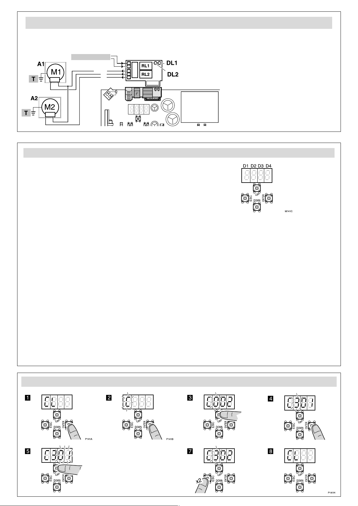
C0Number of operators 01, 20101: one operator,
02: two operators (only available with C301)
1Operator 1 turning direction
(operator 2 also changes)
01, 20101: direction A, 02: direction B. Check direction by
pressing ST1 (open) and ST2 (close)
2Operator 2 turning direction
(operator 1 also changes)
01, 20101: direction A, 02: direction B. Check direction by
pressing ST1 (open) and ST2 (close)
3Gate type 01... 30101: swing, 02: sliding, 03: up-and-over
4Opening safety device
(photocell)
0,10,10000: not installed,
10: no testing, 11: with testing
5Closing safety device (photocell)
Closing photocell with C520 or
C521, also prevents gate
opening from starting
0...2 0,10000: not installed,
10: no testing, 11: with testing
20: no testing, 21: with testing
6Electrolock / electromagnet
C630 and C640 are used to
manage an external relay at
24Vdc, connected to cable
connectors P11-P12. The
electromagnet must be
externally supplied (through this
relay) and sized in line with the
electromagnets used.
0...4 0...4 00 00: not installed
1X: electrolock without reverse impulse.
Programmable electrolock time: 3 seconds
with X=0(by default), 3.5s with X=1, 4s with
X=2, 4.5s with X=3, 5s with X=4.
2X: electrolock with reverse impulse.
Programmable time (electrolock/motor
reverse): 4.5/1.5 seconds with X=0(by default),
5/2s with X=1, 5.5/2.5s with X=2, 6/3s with
X=3, 6.5/5s with X=4.
30: electromagnet without impulse
40: drop electromagnet
7Encoder / Limit switches
The cabling depends on the type
of operator selected (C301,
C302 or C303); see the
corresponding wiring diagram)
0 0...5 00 00: not installed;
01: with single encoder;
02: with limit switches;
03: with dual encoder;
04: with encoder and limit switches (not available
with C301 selected);
05: VULCAN VUS and ATLAS (ATS) G6xxI (only
available with C301 or C303 selected)
8Radio card 01, 20201: RSD card (no decoder);
02: two channel decoder card
9Safety strip 01, 20101: mechanical; 02: resistive 8k2
ASlowdown 0 0...3 02 00: no slowdown;
01: slowdown in opening and closing;
02: slowdown in opening;
03: slowdown in closing
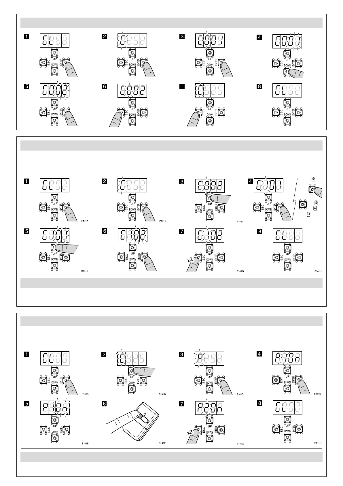
P1
Total opening radio programming
oç Programmes total opening channel and code
2
Pedestrian opening radio programming
oç Programmes pedestrian opening channel and code
3Programming gate travel oç Programmes the operations in accordance with the
configuration CA
F1Key command by way of ST1
and ST2 pushbuttons.
With F101 the gate (total or
pedestrian) can be kept open by
keeping ST1 or ST2 pressed
down respectively. This allows
the time scheduler to be used in
combination with F2 and/or F4
K00.
00...40100: ST1 and ST2 without effect, the key commands
are given by radio (channel 1: total opening-
closing, channel 2: pedestrian opening-closing)
01:
ST1 total opening-closing, ST2 pedestrian opening-
closing
02: ST1 total opening, ST2 total closing
03: dead-man mode (the display shows HP.);
04: dead-man mode in closing
2Automatic or step-by-step
operation mode and standby
time (in seconds) in automatic
mode
0..5. 0...9 00 00: step-by-step mode
01:
automatic mode and standby time 1 second
;
...
59: automatic mode and standby time 59 sec.;
1.0: 1 min. 0 sec.; ...; maximum 4 minutes
3Pedestrian opening (%) 0...9 0...9 40 00: pedestrian opening is not carried out,
10: 10% of total opening, etc
4Pedestrian closing mode 0...5 0...9 00 00: semi-automatic mode
01:
automatic mode and stand-by time 1 second
;
...
59: automatic mode and stand-by time 59 sec.;
1.0: 1 min. 0 sec.; ...; maximum 4 minutes
Complete programming chart (I)
16
D1 D2 Parameter D3 D4
Default
option
Options or values
A0Flashing light 01, 20101: output with voltage, with no pre-warning
02: output with voltage, with pre-warning
1Garage light time 0..5. 0...9 03 03 = 3 sec.; 59 = 59 sec.; 2.5 = 2 min. 50 sec.;
....; maximum 4 minutes
2Torque/nominal force 0 1...9 09 01: minimum,..., 09: maximum
3Regulation of torque/force and
slowdown speed 0 1...9 09 01: minimum,..., 09: maximum
5Recede after closing (ensures the
operator does not become
seized on the stopper)
0 0...5 00 00: no recede; ...;
05: maximum recede
6Torque/maximum trapping force
(level of increase relative to
nominal)
The D3 digit allows the level to
be adjusted during opening;
The D4 digit allows the level to
be adjusted during closing
0...9 0...9 00
00
: disabled in opening and closing;
01
: disabled in opening and level 1 in closing;
10
: level 1 in opening and disabled in closing;
….;
65
: level 6 in opening and level 5 in closing;
…;
99
: level 9 in opening and closing
7(Opening or closing) photocell
used during standby (in
automatic mode only)
0 0...2 02 00: does not affect standby time
01: immediate close when the photocells are
released
02: restarts standby time
8Effect of the ST1-ST2
pushbuttons during standby (in
automatic mode only)
00...20200: has no effect during standby
01: brings about closing after 3 seconds
02: restart standby time
9Opening mode 01...30201: community opening
02: step-by-step alternative shutdown
03: automatic alternative shutdown (if F200 is
selected, A903 changes to A902)
ALapse between leaves in
opening and closing 0...9 0...9 22 00: no lapse in opening or closing (only apply in
gates without overlap);
XY:Xlapse in opening
(X=1: 1 second, ... , X=9: 9 seconds)
Ylapse in closing
(Y=1: 1 second, ... , Y=9: 9 seconds)
bUse of the EPS1 card connector
For parameters Ab02 and Ab03,
use the EPS1 card and bridge the
network input cable connectors
instead of connecting them to
the network (see “Brake
connection” diagram).
0 0...3 00 00: use for standard traffic light;
01: use for brakes
02: NC contact with gate open (L1-COM) and
gate closed (L2-COM)
03: impulse 1 second Open (L1-COM) when
starting opening and Close (L2-COM) when
starting closing. Allows another board to be
activated.
CHydraulic pressure maintenance 0 0...6 00 00: no pressure maintenance;
01: every 0.5 hours; 02: every 1 hour;
03: every 2 hours; 04: every 6 hours;
05: every 12 hours; 06: every 24 hours
dRam 00,1 00 00: no ram; 01: with ram
ESpecial features 0 0...2 00 00: no special function;
01: opening photocell C4 programmed for
pedestrian passage;
02: industrial;
N0Programming lock key
Be sure to remember any key
used, for future access to the
programming
0 0,1 0000 The preset option is 0000 (no key). If any figure is
changed, this is considered a key.
Select the required key (starting with D1) using
UP and DOWN. Press ESC to cancel or ENTER to
confirm and move to D2, and so on.
1Total operations completed XX Indicates the hundreds of cycles completed (for
example, 68 indicates 6,800 cycles completed)
2Partial operations completed XX Indicates the hundreds of cycles completed. This
can be reset by pressing ST1, ST2 and ENTER at
the same time.
t0FTP communication Oç Immediate communication with the server
1GSM signal intensity XX Indicates signal intensity
Complete programming chart (and II)

Other manuals for VIVO-M203

3

This manual suits for next models

1

Other Erreka Controllers manuals

Erreka AZIMUT User manual

Erreka

Erreka AZIMUT User manual

Erreka ERTAIN 4 SYSTEM User manual

Erreka

Erreka ERTAIN 4 SYSTEM User manual

Erreka V2 CICLON User manual

Erreka

Erreka V2 CICLON User manual

Erreka VIVO-M101 User guide

Erreka

Erreka VIVO-M101 User guide

Erreka GLOBAL 4 User manual

Erreka

Erreka GLOBAL 4 User manual

Erreka VULCAN User guide

Erreka

Erreka VULCAN User guide

Erreka VIVO-M201 User guide

Erreka

Erreka VIVO-M201 User guide

Erreka ATLAS G 605 User guide

Erreka

Erreka ATLAS G 605 User guide

Erreka ROLL 60C User manual

Erreka

Erreka ROLL 60C User manual

Erreka LINCE LIS424 User guide

Erreka

Erreka LINCE LIS424 User guide

Erreka ERGOS Series User manual

Erreka

Erreka ERGOS Series User manual

Popular Controllers manuals by other brands

dixell XR01-02CX Installing and operating instructions

dixell

dixell XR01-02CX Installing and operating instructions

Airwell RCW30 user manual

Airwell

Airwell RCW30 user manual

EuroLite TP-310 user manual

EuroLite

EuroLite TP-310 user manual

Buderus RC20 operating instructions

Buderus

Buderus RC20 operating instructions

ACS contsys MIR-491 operating instructions

ACS contsys

ACS contsys MIR-491 operating instructions

AUMA SGExC 05.1 Operation instructions

AUMA

AUMA SGExC 05.1 Operation instructions

Norac UC4 Plus Rogator 64 Series installation manual

Norac

Norac UC4 Plus Rogator 64 Series installation manual

Ransburg 9060 Service manual

Ransburg

Ransburg 9060 Service manual

Smartrise C4 user manual

Smartrise

Smartrise C4 user manual

Airwell RCW22 Installation and owner's manual

Airwell

Airwell RCW22 Installation and owner's manual

Skydroid H12 manual

Skydroid

Skydroid H12 manual

Vello Extenda LW-100 quick start guide

Vello

Vello Extenda LW-100 quick start guide

YASKAWA CIPR-GA70C Series Initial Steps

YASKAWA

YASKAWA CIPR-GA70C Series Initial Steps

Extron electronics Basic MediaLink Controllers MLC 52 IR user manual

Extron electronics

Extron electronics Basic MediaLink Controllers MLC 52 IR user manual

SOMFY animeo IB+ 9001614 installation guide

SOMFY

SOMFY animeo IB+ 9001614 installation guide

National Instruments IC-3121 user manual

National Instruments

National Instruments IC-3121 user manual

Liebert AC4 user manual

Liebert

Liebert AC4 user manual

FAE VRTMT 8 manual

FAE

FAE VRTMT 8 manual

manuals.online logo
manuals.online logoBrands
  • About & Mission
  • Contact us
  • Privacy Policy
  • Terms and Conditions

Copyright 2025 Manuals.Online. All Rights Reserved.