manuals.online logo
Brands
  1. Home
  2. •
  3. Brands
  4. •
  5. ESA
  6. •
  7. Industrial PC
  8. •
  9. ESA ERGO222A Series Assembly instructions

ESA ERGO222A Series Assembly instructions

This manual suits for next models

1

Other ESA Industrial PC manuals

ESA LUMIA BOX User manual

ESA

ESA LUMIA BOX User manual

ESA LUMIA2MINIA1350 User manual

ESA

ESA LUMIA2MINIA1350 User manual

Popular Industrial PC manuals by other brands

Chipsee PPC-A72-101 manual

Chipsee

Chipsee PPC-A72-101 manual

Advantech UNO-2184G user manual

Advantech

Advantech UNO-2184G user manual

MSI MS-9A76 manual

MSI

MSI MS-9A76 manual

Stackrack THOR200 user manual

Stackrack

Stackrack THOR200 user manual

Moxa Technologies DA-682C Series user manual

Moxa Technologies

Moxa Technologies DA-682C Series user manual

Nodka eBOX-3000-ETC user manual

Nodka

Nodka eBOX-3000-ETC user manual

Siemens SIMATIC IPC627E Quick install guide

Siemens

Siemens SIMATIC IPC627E Quick install guide

Artila Matrix-516 user guide

Artila

Artila Matrix-516 user guide

MSI MS-9A89 user manual

MSI

MSI MS-9A89 user manual

Siemens SIMATIC Rack PC 840 V2 Getting started

Siemens

Siemens SIMATIC Rack PC 840 V2 Getting started

Advantech IPPC-6152A user manual

Advantech

Advantech IPPC-6152A user manual

Beckhoff CX9020 manual

Beckhoff

Beckhoff CX9020 manual

Dell Embedded Box PC 5000 Installation and operation manual

Dell

Dell Embedded Box PC 5000 Installation and operation manual

IBASE Technology ASB200-918 Series user manual

IBASE Technology

IBASE Technology ASB200-918 Series user manual

Lenovo ThinkCentre M90q Hardware Maintenance Manual

Lenovo

Lenovo ThinkCentre M90q Hardware Maintenance Manual

IXXAT Econ 100 Hardware manual

IXXAT

IXXAT Econ 100 Hardware manual

Kontron KBox A-151-TGL user guide

Kontron

Kontron KBox A-151-TGL user guide

AXIOMTEK ICO500-518 Series user manual

AXIOMTEK

AXIOMTEK ICO500-518 Series user manual

manuals.online logo
manuals.online logoBrands
  • About & Mission
  • Contact us
  • Privacy Policy
  • Terms and Conditions

Copyright 2025 Manuals.Online. All Rights Reserved.

Rev. 0 Date: 20/02/2019 405.1300.254.0
ERGO PC INDUSTRIALE
ERGO INDUSTRIAL PC
ERGO PC INDUSTRIEL
ERGO INDUSTRIAL PC
ERGO PC INDUSTRIAL
Dimensioni / Dimensions / Dimensions / Abmessungen / Dimensiones
ERGO222Axxxxx
ERGO222Txxxxx
Montaggio supporto VESA / VESA support mounting / Montage du support VESA /
Montage des VESA-Ständers / Montaje de soporte VESA
Montaggio supporto VESA / VESA support mounting / Montage du support VESA /
Montage des VESA-Ständers / Montaje de soporte VESA
Montaggio copertura cavi / Cab e cover assemb y / Fixation du cache-câb e /
Befestigung der Kabe abdeckung / Fijación cubierta cab e
Posteriore / Rear side / Face arrière / Rückseiten / Posterior
A Alimenta ione
Alimenta ioneAlimenta ione
Alimenta ione
Power supply, Alimentation,
Spannungsversorgung, Alimentación
E #
##
#1
11
1
-
--
-
ETH10/100/1000 Mbit
ETH10/100/1000 Mbit ETH10/100/1000 Mbit
ETH10/100/1000 Mbit –
––
–
RJ45
RJ45RJ45
RJ45
Porta
Porta Porta
Porta ETH
ETH ETH
ETH 1
11
1,
, ,
, Porte ETH
ETH ETH
ETH 1
11
1,
, ,
, ETH
ETH ETH
ETH 1
11
1
Schnittstelle
Puerto ETH
ETH ETH
ETH 1
11
1
B #
##
#2
22
2
Port
PortPort
Porta
aa
a
DP
DPDP
DP
DP port, Porte DP, DP Schnittstelle, Puerto DP
F USB
USBUSB
USB-
--
-A
AA
A
Porta USB, USB port, Port USB, USB-Schnittstelle,
Puerto USB
C #
##
#1
11
1
Port
PortPort
Porta
aa
a
DP
DPDP
DP
DP port, Porte DP, DP Schnittstelle, Puerto DP
G Porta
Porta Porta
Porta COM
COMCOM
COM
Porta seriale, Serial port, Port sériel, Serielle
Schnittstelle, Puerto serie
D #
##
#2
22
2
-
--
-
ETH10/100/1000 Mbit
ETH10/100/1000 Mbit ETH10/100/1000 Mbit
ETH10/100/1000 Mbit –
––
–
RJ45
RJ45RJ45
RJ45
Porta
Porta Porta
Porta ETH
ETH ETH
ETH 2
22
2,
, ,
, Porte ETH
ETH ETH
ETH 2
22
2,
, ,
, ETH
ETH ETH
ETH 2
22
2
Schnittstelle
Puerto ETH
ETH ETH
ETH 2
22
2
H VGA - Output
VGA port, Porte VGA, VGA Schnittstelle, Puerto
VGA
Sostituzione de a batteria / Substituting the battery / Substitution de a pi e /
Austauschen der Batterie / Sustitución de a batería
IT
a. Spegnere ERGO.
b. Rimuovere la copertura posteriore.
c. Rimuovere la scheda madre.
d. Sostituire la batteria della scheda madre (vedi manuale scheda madre).
ATTENZIONE: Inserire la batteria nuova rispettando il tipo e le polarità.
e. Rimontare la copertura e la scheda madre
EN
a. Switch o ERGO.
b. Remove the back cover.
c. Remove the motherboard.
d. Replace the battery on the motherboard (see motherboard manual).
ATTENTION: Insert the new battery checking that the polarities are correct.
Discarded batteries should be placed in appropriate containers.
e. Replace back cover and the motherboard.
FR
a. Éteindre le ERGO.
b. Retirez la couverture arrière.
c. Retirez la carte mère.
d. Remplacer la pile sur la carte mère (voir le manuel de la carte mère).
ATTENTION : Introduire la nouvelle pile en respectant les polarités. Ne pas jeter les
piles dans la nature.
e. Remonter le couvercle et la carte mère.
DE
a. Das ERGO ausschalten.
b. Ent ernen Sie die hintere Abdeckung.
c. Ent ernen Sie das Hauptplatine.
d. Ersetzen Sie die Batterie au der Hauptplatine (siehe Gebrauchsanweisung der
Hauptplatine).
ACHTUNG: Bei Batteriewechsel au korrekte Polung achten. Altbatterien müssen
entsprechend entsorgt werden.
e. Wieder zusammenbauen Sie die Abdeckung und das Hauptplatine wieder an
ES
a. Apague el ERGO.
b. Retire la tapa posterior.
c. Retire la placa base.
d. Reemplazar la batería en la placa base (ver el manual de la placa base).
ATENCIÓN: Introduzca la nueva batería observando las polaridades. Tire las baterías
descargadas a los contenedores apropiados.
e. Vuelve a colocar la tapa y la placa base.
A imentazione / Power supp y / A imentation / Spannungsversorgung /
A imentación
AVVERTENZA
/
/ /
/ WARNING
/
/ /
/ AVERTISSEMENT
/
/ /
/ HINWEIS
/
/ /
/ ADVERTENCIA
IMPORTANTE: eggere attentamente queste istruzioni prima de ’insta azione de
prodotto.
IMPORTANT: P ease read carefu y these instructions before mounting the product.
IMPORTANT: ire attentivement ces instructions avant ’insta ation du produit.
WICHTIG: esen Sie die Hinweise sorgfä tig durch bevor Sie Insta ationen durchführen.
IMPORTANTE: eer estas instrucciones con cuidado antes de a insta ación
producto.
Power supp y 4 pins connectors
1
24 VDC
2 0 VDC
3 Not Connected
4 Protective ground
Significato dei pin del connettore di alimenta ione
Power connector pin-out
Signification des pins du connecteur d’alimentation
Anschluß des Versorgungssteckers
Significado de los pines de el conector de alimentación
~
+- 24V
3
+24V
PE
0V
ERGO
DEVICE
PE
N
L1
4
1
2
Collegamento consigliato / Recommended power connection / Connexion
conseillée / Empfohlene Verdrahtung / Empfohlene Verdrahtung
A imentazione / Power supp y / A imentation / Spannungsversorgung /
A imentación
~
+-
24V
PE
N
L1
~
-
24V
+
PE
N
L1
Attenzione: Queste due con igurazioni danneggiano gravemente il prodotto.
Warning: These two con iguration will seriously damage components.
Attention: Ces deux con igurations peuvent endommager certains composants.
Warnung: Diese beiden Anschlussarten ühren zu Schäden am Gerät.
Atencion: Las dos con iguraciones de arriba dañan gravemente el EW.
IMPORTANTE
La massa dei dispositivi collegati alle porte di comunica ione seriali e/o parallele deve essere tassativamente allo
stesso poten iale dello 0V di alimenta ione del prodotto ERGO. La circola ione di una corrente tra lo 0V di
alimenta ione e la massa delle porte di comunica ione potrebbe causare il danneggiamento di alcuni componenti
di ERGO o dei dispositivi ad esso collegati.
IMPORTANT
The earth of the devices connected to the serial and/or parallel communication ports MUST have the same
potential as the 0V supply of ERGO. The circulation of current between the 0V supply and the earth of the
communication ports could cause damage to certain components of the ERGO or of the devices connected to it.
IMPORTANT
La masse des dispositifs connectés aux ports de communication parallèls ou sériels doit formellement être au
même potentiel qu’il 0V d’alimentation du ERGO. La circuòation d’un courant entre il 0V d’alimentation et la
masse des ports de communication pouvait causer des dommages aux composants du ERGO ou des dispositifs
connés.
WICHTIG
Die Erde der Parallelen und/order Seriellen Datenleitung müssen das gleiche Potential haben wie die Erde der
Spannungsversorgung vom ERGO. Eine nicht korrekte Erdung der Spannungsversorgung und der
Datenleitungen können schwere Schäden an den ERGO sowie an den angeschlossene Komponenten hervor
rufen.
ATENCION
La masa de los dispositivos conectados en los puertos de comunicación serie y/o paralelo tiene que estar
conectada imprescindiblemente al mismo potencial del 0V de alimentación del ERGO. La circulación de una
corriente entre el 0V de alimentación y la masa de los puertos de comunicación podría causar daños a algunos
componentes del ERGO o bien a algunos dispositivos conectados.
Temperatura di esercizio / Working temperature / Température d’exercice /
Betriebstemperatur / Temperatura de servicio
0 / +50°C
Cavi di co egamento / Connection cab es / Câb es de raccordement /
Schnittste enkabe / Cab es de conexión
IT
Per limitare al massimo l’influen a dei disturbi è necessario utili are cavi schermati di buona
qualità.
Caratteristiche del cavo di collegamento seriale:
• Resisten a in corrente continua - Max. 151 Ohm/Km
• Accoppiamento capacitivo - Max. 29pF/m
• Schermatura > 80% oppure Totale
In ogni caso:
• Cercare il percorso più breve.
• Effettuare la posa separata da cavi disturbati e/o cavi di poten a.
• Utili are connettori con gusci metallici o di plastica conduttiva.
Collegare la schermatura del cavo seriale attenendosi alle indica ioni riportate nell’immagine
seguente (FIG.1).
NOTA: La cal a deve risultare connessa elettricamente sia al corpo connettore che al
coperchio.
Lo schermo del cavo deve risultare connesso elettricamente sia alla custodia che al corpo
del connettore stesso da ambo i lati del cavo.
Nel caso che non possa essere eseguita l'opera ione di collegamento schermo lato
Dispositivo causa tipo di connettore seriale particolare, la schermatura stessa dovrà essere
portata esternamente al connettore e collegata al morsetto di terra.
EN
In order to limit as much as possible the influence of these disturbances good quality
shielded cables must be used.
Specifications of serial connection cable:
• Direct current resistance - Max. 151 Ohm/Km
• Capacity coupling - Max. 29pF/m
• Shielding > 80% or total
Always:
• Find the shortest route.
• Lay disturbed cables separately.
• Use connectors with metal or conduc-tive plastic shells.
Connect the serial cable shield in accordance with the instructions on the following image
(FIG.1).
NOTE: The braiding must be electrically connected both to the connector body and shell.
The interface cable braiding must be electrically connected both to the shell and the body
of the connector at both ends of the cable.
If the connection operation cannot be carried out at the Device side due to the particular
type of serial connector, the braiding will have to be taken outside the connector and
connected to the earth terminal.
FR
Pour limiter au maximum l’influence de ces parasites il faut utiliser des câbles blindés de
bonne qualité
Caractéristiques du câble de raccordement sériel :
• Résistance en courant continu - Max. 151 Ohm/Km
• Accouplement capacitif - Max. 29pF/m
Cavi di co egamento / Connection cab es / Câb es de raccordement /
Schnittste enkabe / Cab es de conexión
• Blindage > 80% ou bien total
Dans tous les cas :
• Chercher le parcours le plus bref.
• Effectuer la pose séparée des câbles perturbés.
• Utiliser des connecteurs du type spécial à carcasse avec gaines métalliques ou en
plastique conductible.
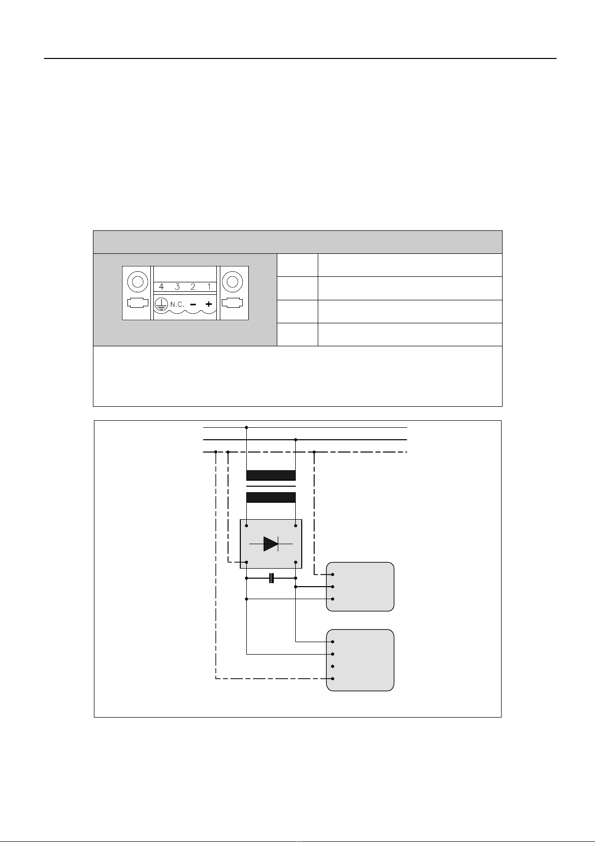
Raccorder le blindage du câble sériel en se tenant strictement aux indications reportées
dans l'image suivante (FIG.1).
NOTE: La gaine doit être connectée électriquement au corps du connecteur et à son
habillage.
La protection du câble d’interface doit résulter électriquement connectée aussi bien à la
gaine qu’au corps du connecteur luimême des deux côtés du câble.
Dans le cas où l’opération de raccordement protection côté Périphérique ne puisse pas être
exécutée à cause du type particulier de connecteur sériel, le blindage même devra être
porté extérieurement au connecteur et raccordé à la borne de terre.
DE
Da die serielle Kommunikation extrem anfällig für Störungen ist, müssen ur Vermeidung
dieser Störungen qualitativ hochwertige abgeschirmte Leitungen verwendet werden.
Empfehlungen für serielle Schnittstellenkabel:
• Gleichstromwiderstand - Max. 151 Ohm/Km
• Kapa itive Kopplung - Max. 29pF/m
• Abschirmung > 80% oder Komplettschirmung
In jedem Fall:
• Leitungen auf dem kür esten Weg verlegen.
• Datenleitungen getrennt von Lastleitungen verlegen.
• Steckergehäuse aus Metall oder leitfähigem Kunststoff verwenden.
Schließen Sie die Abschirmung des seriellen Kabels gemäß den Anweisungen in der
folgenden Abbildung an (FIG.1).
Bemerkung: Das Schirmgeflecht muß elektrisch sowohl mit dem Steckerkörper als auch mit
dem Gehäuse verbunden sein.
Der Schirm des Schnittstellenkabels muss sowohl an das Gehäuse als auch an den
Steckerkörper an beiden Kabelenden angeschlossen werden. Falls der geräteseitige
Anschluss der Kabelabschirmung aufgrund eines besonderen seriellen Steckertyps nicht
möglich ist, muss die Abschirmung aus dem Steckverbinder herausgeführt und an eine
Erdklemme angeschlossen werden.
ES
Para limitar al máximo sus influencias, es necesario utili ar cables apantallados de calidad.
Características del cable de conexión en serie:
• Resistencia en corriente continua - Máx. 151 Ohm/Km
• Acoplamiento de capacidad - Máx. 29pF/m
• Apantallado > 80% o tota
En todo caso:
• Busque el recorrido más corto.
• No realice el tendido junto a cables con perturbaciones.
• Utili ar conectores tipo con carcasa metálicos o de plástico conductivo.