ESA ESA-3600 User manual

HYBRID INVERTER USER MANUAL
(V1.0)
ADD: 99 Coventry Street, Southbank, VIC 3004, Australia
Tel: +61 133 765

1 Notes On This Manual .......................................................................................................1
1.1 Validity .................................................................................................................1
1.2 Target Group .....................................................................................................1
1.3 Additional Information ..................................................................................1
1.4 Storage Of The Manuals ...............................................................................1
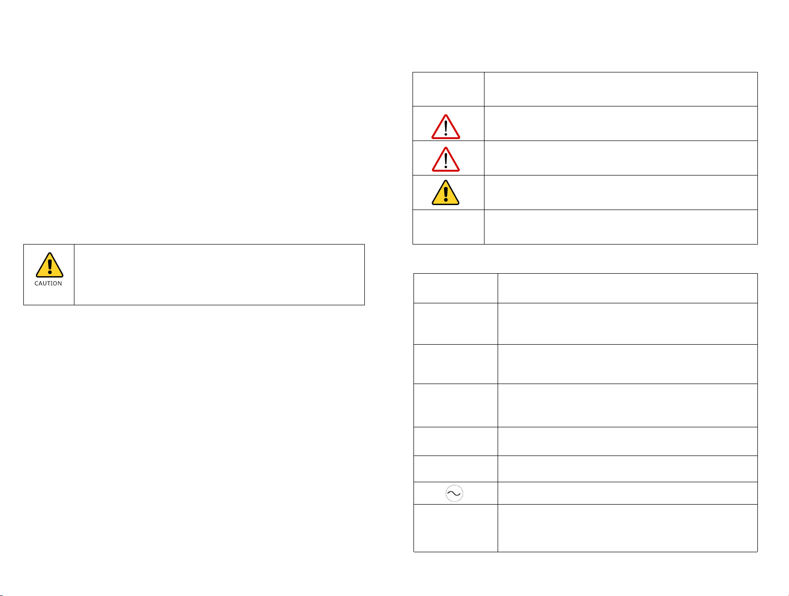
1.5 Symbols Used ...................................................................................................2
1.6 Markings On This Product ...........................................................................2
2 Safety And Conformity ......................................................................................................3
2.1 Safety Instructions ...........................................................................................3
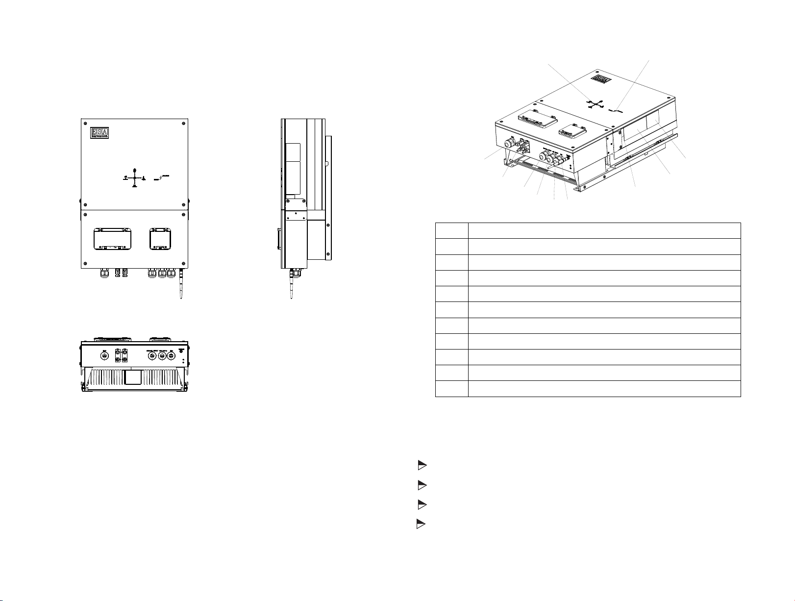
3 Product Description ...........................................................................................................5
3.2 Information Of The Unit ...............................................................................5
3.3 Storage Of Inverter .........................................................................................6
4 Unpacking ..............................................................................................................................7
5 Installation And Electrical Connection ..........................................................................8
5.1 Safety ....................................................................................................................8
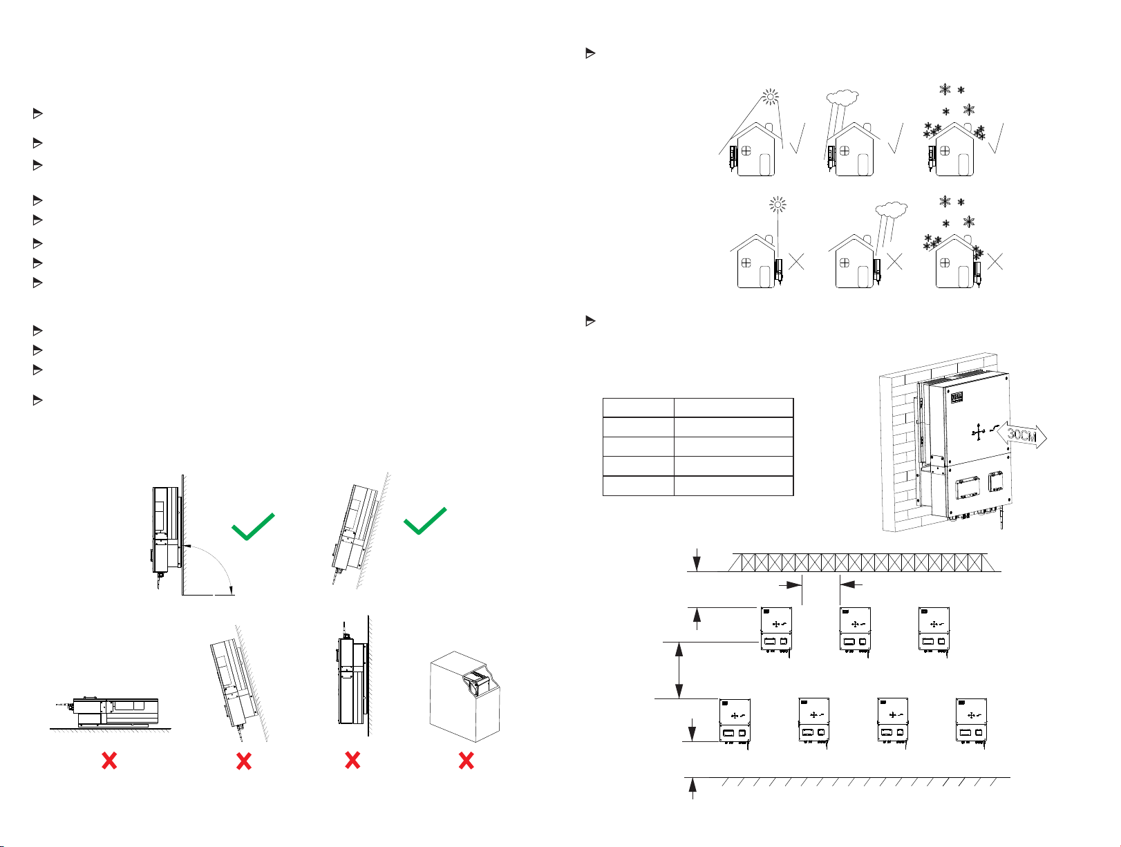
5.2 Selecting The Installation Location .......................................................9-10
5.3 Mounting The Inverter With Bracket ........................................................11
5.4 Fixed The Inverter On The Wall ..................................................................12
5.5 Check Inverter Installation Status ..............................................................13
5.6 Electrical Connection ......................................................................................13
5.6.1 Safety ................................................................................................................13
5.6.2 System Diagram With Inverter Electrical ..............................................13
5.6.3 Connect To The Grid(AC Utility) ..............................................................14
5.6.4 Connect To The Back-up ............................................................................15
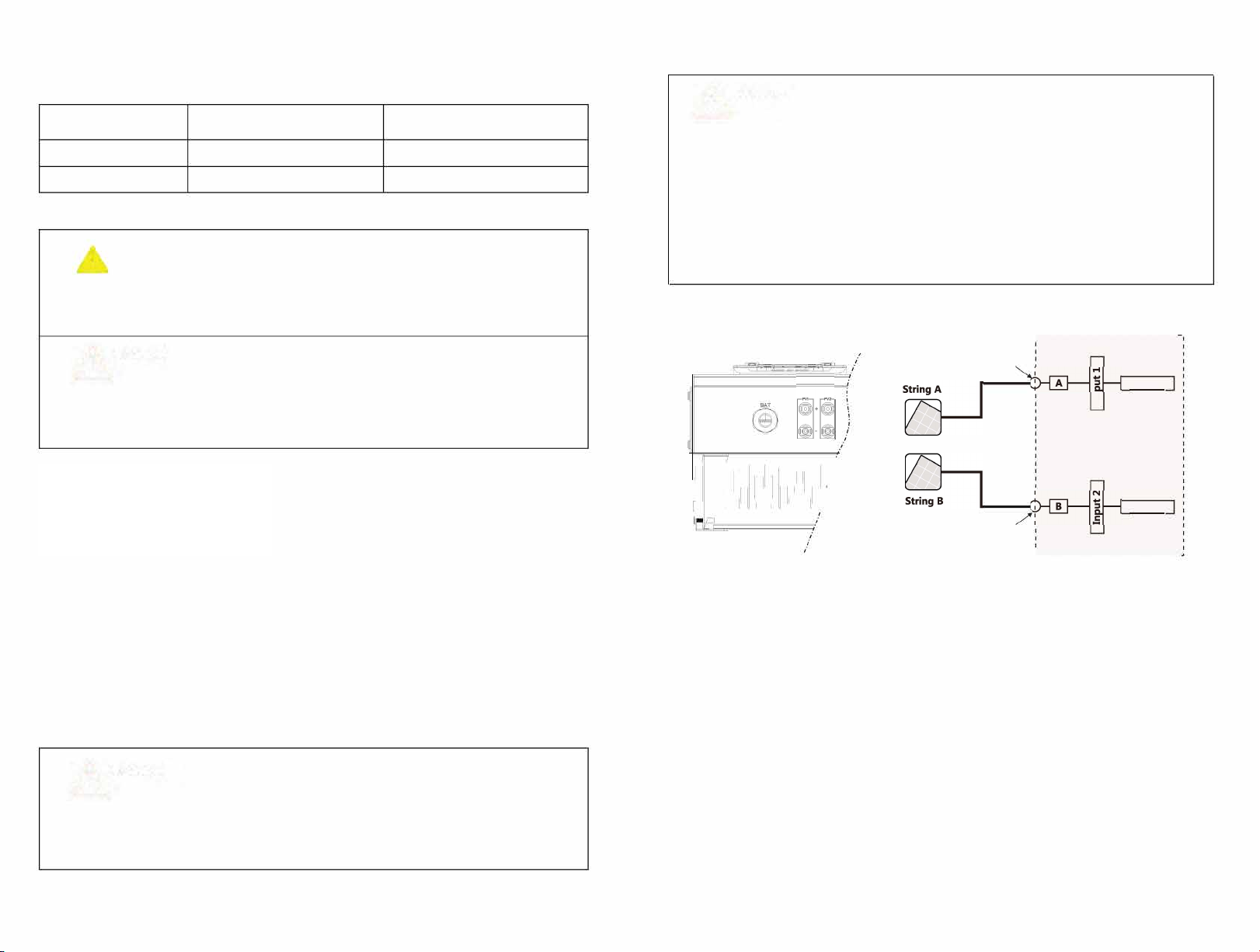
5.6.5 Connect To PV Panel ...................................................................................16
5.6.6 Connect To The Battery .......................................................................17-18
5.6.7 Load Monitor Connect To The Inverter ................................................19
5.6.8 Grounding Connection …………………………………...................................20
5.6.9 Communication wiring diagram of lithium battery…………………...21
5.7 Earth Fault Alarm Connection .....................................................................22
6 Communications …………………………………………………………….......................23
6.1 Wi-Fi/GPRS ……………………………………………………………………...23
6.2 The DRMO Function for SAA Certification ……………………….23
6.3 Set Inverter Regulations …………………………………………………..24
6.4 WiFi Dongle setting using Laptop …………………………………...24
6.4.1 Connecting WiFi Dongle to the Internet ………………….25-26
6.5 Monitoring your Inverter System …………………………………....27
7 The Inverter Parameter setting …………………………………….....................…28
7.1 Setting Interface ………………………………………………………..…...28
7.2 Volt-Watt Function ……………………………………...........…………..28
7.3 Set volt-var function ..........………………………………………………29
8 Start-Up And Shut Down Of The Inverter ...................................................30
8.1 Start-Up The Inverter .....................................................................30
8.2 Disconnecting The Inverter ..........................................................30
9 Maintenance And Cleaning ..............................................................................31
9.1 Checking Heat Dissipation ............................................................31
9.2 Cleaning The Inverter .....................................................................31
9.3 Checking The DC Switch ...............................................................31
10 Decommissioning ..............................................................................................31
10.1 Dismantling The Inverter ............................................................31
10.2 Packing The Inverter .....................................................................31
10.3 Storing The Inverter ......................................................................31
11 Work Modes ........................................................................................................32
12 Manufacturer Warranty ...................................................................................32
13 Technical Data ..............................................................................................33-34
Contents
8.3 Commissioning of the Hybrid Inverter .....................................30
8.4 Country Code Settings ...................................................................30

This manual is for qualified personnel that have received training and
have demonstrated skills and knowledge in construction and
operation of this device. Qualified personnel are trained to deal with
the dangers and hazards involved in installing electric devices.
1 Notes On This Manual
1.1 Validity
This manual describes the assembly, installation, commissioning and mainte nance of the ESA
hybrid inverter.
This manual does not cover any details concerning equipment connected to the unit ( e.g.
PV modules). Information concerning the connected equipment is available from the
manufacturer's instructions.
1.2 Target Group
1.3 Additional Information
Find further information on special topics on our website.
1.4 Storage of the manuals
The manual and other documents must be stored in a convenient place and be available at all
times. We assume no liability for any damage caused by failure to observe these instructions.
Description
WARNING indicates a hazardous situation which, if not avoided,
will result in death or serious injury.
CAUTION indicates a hazardous situation which, if not avoided,
could result in a minor or moderate injury.
NOTE Failure to observe this warning may lead to damage to
property.
Warning regarding dangerous voltage
The product works with high voltage. All work on the product
must only be performed as described in its documentation and
by qualified trades people.
Beware of hot surface
The product can become hot during operation.
Do not touch the product during operation.
Observe the operating instructions
Read the product's documentation before working on it.
Follow all safety precautions and instructions as described in
the documentation.
Point of connection for grounding protection.
Direct Current (DC)
Alternating Current (AC)
Signals danger due to electrical shock and indicates the
times (5 minutes) to allow after the inverter has been turned
off and disconnected to ensure safety in any installation
operation.
1.5 Symbols Used
1.6 Markings On This Product
The following types of safety instructions and general information appear in this
document as described below:
DANGER indicates a hazardous situation which, if not avoided,
will result in death or serious injury.
Manual – Read the Manual!
Symbol
1 2
A

2 Safety And Conformity
2.1 Safety Instructions
Danger To Life Due To Lethal Voltages!
Lethal voltages are present within the unit and on the power supply lines.
Therefore, only authorized electricians may install and open the unit. Even when
the unit is disconnected, high contact voltages may still be present within the
unit.
Danger Of Burn Injuries Due To Hot Enclosure Parts!
During operation, the four sides of the enclosure lid and the heat sink may become
hot. Only touch the front enclosure lid during operation.
Grounding The PV Generator
Comply with the local requirements for grounding the PV modules and the PV
generator. We recommend connecting the generator frame and other electrically
conductive surfaces in a manner which ensures continuous conduction with
ground in order to have optimal protection of the system and personnel.
Capacitive Discharge Currents
PV modules with large capacities relative to earth, such as thin-film PV modules
with cells on a metallic substrate, may only be used if their coupling capacity does
not exceed 470nF. During feed-in operation, a leakage current flows from the cells
to earth, the size of which depends on the manner in which the PV modules are
installed (e.g. foil on metal roof ) and on the weather (rain, snow). This "normal"
leakage current may not exceed 30mA due to the fact that the inverter would
otherwise automatically disconnect from the electricity grid as a protective
measure.
DC and AC Breaker
Disconnecting the unit securely from the grid and the PV generators, battery using DC and
AC breaker. DC and AC breaker shall be able to disconnect all non- ground conductors after
installation.
Grounding The PV Modules
This unit is a transformer-less inverter. It has no galvanic separation. Do not earth the DC
circuits of the PV modules to the inverter. Only Earth the mounting frame. If you bond the
PV modules to the inverter you will receive an error message "PV ISO Low".
Qualification Of Skilled Workers
Knowledge of how an inverter works and is operated
Instruction in how to deal with the dangers and risks associated with installing
and using electrical devices and plants
Training in the installation and commissioning of electrical devices and plants
Knowledge of all applicable standards and guidelines
Knowledge and observance of this manual and all safety instructions
NOTE
NOTE
NOTE
No one should be opening the unit
3 4

3 Product Description
3.1 Inverter Overview
A The Inverter Power Flow Direction Indicator
B The Inverter Operation Status Indicator
C
PV Input Terminals
D
Battery Input
E Essential Supply (AC OUT)
F Grid Supply (AC IN)
G COM
H Wireless
I Inverter Serial No.
J Spec Label
K Warning Signals Label
3.3 Storage of Inverter
If you want to storage the unit in your warehouse, you should choose an appropriate
location to store the inverter.
The unit must be stored in original packaging.
The storage temperature should be always between -25℃ and +60℃.
The storage relative humidity should be always between 0 and 95%.
If there are a batch of unit need to be stored, the maximum layers for original
carton is four.
Note; The battery storage much be according with the battery manufacturers
specifications.
Figure 1
Figure 2
3.2 Information of the Unit
The unit is bidirectional which applies to the PV system with battery storage. Energy produced
by the PV system is used to optimize self-consumption. Excess energy is used to charge the
batteries, and then fed into the public grid when the PV energy is adequate.
When PV energy output is insufficient to support connected loads, the system automatically
draws energy from the batteries if battery capacity is sufficient. If the battery capacity is
insufficient to meet own consumption requirements, electricity will be drawn from the public
grid.
I
J
K
AB
C
DEGH
F
5 6

5 Installation and Electrical Connection
5.1 Safety
Danger to life due to fire or explosion
Despite careful construction, electrical devices can cause fires. Do not install the
inverter on easily flammable materials and where flammable materials are stored.
Risk of burns due to hot enclosure parts
Mount the inverter in such a way that it cannot be touched inadvertently.
Item Name Quantity
A Inverter 1
B Mounting Frame 1
C
D
E
F
G
H
I
J
AB C
D E FGH I
J
4 Unpacking
Thoroughly inspect the packaging upon receipt. If any damage to the packaging is visible,
or if you find that the unit is damaged after unpacking, please notify the distributor
immediately.
If there is anything damaged or missing, please contact your supplier. Do not dispose of the
original packaging. If you want to transport the unit, it is better stored in the original packaging.
Complete Delivery Should Contain As Follows:
Figure 3
All electrical installations shall be done in accordance with the IEE Wiring Regulations.
Do not remove the casing. The inverter contains no user serviceable parts. Please refer
servicing to qualified service personnel.
All wiring and electrical installation should only be conducted by a qualified electrician.
Carefull
y remove the unit from its packaging and inspect for external damage. If you find
any imperfections, please contact your local supplier.
The inverter must only be operated with PV generation. Do not connect any other source
of renewable energy to it.
Both AC and DC voltage sources are terminated inside the PV Inverter.
Please disconnect these circuits before servicing.
This unit is designed to feed power to the public power grid (utility) only. Do not connect
this unit to a generator. Connecting the inverter to external devices could result in
serious damage to your equipment.
When a photo-voltaic panel is exposed to light, it generates a DC voltage. When
connected to this equipment, a photo-voltaic panel will charge the DC capacitors.
Energy stored in this equipment's DC capacitors presents a risk of electric shock. Even after the
unit is disconnected from the grid and photo-voltaic panels, high voltages may still exist inside
the PV-Inverter.
Although designed to meet all safety requirements, some parts and surfaces of the
Inverter are still hot during operation. To reduce the risk of injury, do not touch the heat
sink at the back of the PV-Inverter or nearby surfaces while Inverter is operating.
Battery Input Terminations 2
6
7 8
�
K
K WIFI or GPRS 1

Observe the minimum clearances to walls, other inverters or objects as shown in the
diagram below in order to guarantee sufficient heat dissipation.
5.2 Selecting The Installation Location
This is guidance for the installer to choose a suitable installation location, to avoid
potential damages to the device and operators.
The inverter shall not be installed where in direct contact with water or in direct
sunlight.
The unit shall be mounted at least 914 mm (3 feet) above the ground.
The installation location must be suitable for the inverter's weight and dimensions
for a long period of time.
Select the installation location so that the status display can be easily viewed.
Do not install the inverter on structures constructed of flammable materials.
The humidity of the installation location should be 0 - 95%, without condensation.
The installation location must be safely accessible to get to at all times.
Vertical installation or tilted backwards by max. 15° and make sure the connections
of inverter are at the bottom. Never install horizontally and avoid forward and
sideways tilt.
Be sure that the inverter is out of the children's reach.
Do not put anything on the inverter. Do not cover the inverter.
Do not install the inverter near television antenna or any other antennas, antenna
cables.
The Inverter requires adequate cooling space. Provide the best ventilation for the
Inverter to ensure the heat escapes adequately. The ambient temperature should be
below 40° C to ensure optimum operation.
90〫
Figure 4
The inverter should not be installed in direct sunlight, direct heavy water sources or
unstable locations. We recommend that the inverters be installed at a location with some
cover or protection.
Figure 5
Figure 7
Roof
Ground
60cm
60cm
60cm
40cm
Direction Min. clearance(cm)
above 60
below 60
sides 40
front 30
Figure 6
9 10

5.4 Fixed The Inverter On The Wall
Falling equipment can cause serious or even fatal injury. Never mount the inverter on the
bracket unless you are sure that the mounting frame is securely mounted on the wall.
Raise the inverter a little higher than the bracket. Consider the weight during the process
to maintain the balance of the inverter. Hang the inverter on the bracket through the
hooks on bracket.
After confirming the inverter is fixed securely.
Lock the four screws on both sides of the wall bracket.
Ambient Dimensions Using Inverters In Series
There must be sufficient clearance between the individual inverters to ensure that
the ambient air from the adjacent inverter is not taken in.
If necessary, increase the clearance spaces and make sure there is enough fresh air
supply to ensure sufficient cooling of the inverters, and heat dissipation.
5.3 Mounting The Inverter With Bracket
In order to avoid electrical shock or other injury, inspect existing electrical wiring
systems or plumbing installations before drilling holes for bracket fixings
The dimension of bracket as in [Figure 8]:
Fix The Bracket With 6PCS
M6X50 Expansion Bolt
399mm
529 mm
Figure 8
Figure 10
Figure 11
Remove the four screws on both sides of the wall bracket .
Move the wall bracket in the direction of the arrow ; Take away the wall bracket
Figure 9
Arrow Up
Using the mounting frame as a template, drill holes as illustrated in the image below.
11 12

5.6.3 Connect To The Grid (AC Utility)
5.5
Check Inverter Installation Status
Check the mounting of the inverter by trying to raise it from the bracket. The
inverter should remain firmly attached.
Please ensure that the correct mounting surface is selected to allow for vibration of
the inverter during normal operation.
5.6 Electrical Connection
High voltages which may cause electric shocks are present in the conductive parts
of the inverter. Prior to performing any work on the inverter, disconnect the inverter
on the AC side, PV side and battery side.
Do not reverse the polarity of the battery! It will damage the inverter and void
any warranty.
Danger To Life Due To Lethal Voltages!
5.6.1 Safety
Danger of damage to electronic components due to electrostatic discharge. Take
appropriate ESD precautions when replacing and installing the inverter.
Before connecting the DC power cables, the AC supply must be earthed.
Earthing.
5.6.2 System Diagram With Inverter Electrical
Ensure all wiring is
correctly selected and erected in accordance with BS7671:2015, IEE wiring regulations.
Figure 12
NOTE
Figure 14
R1
R2
1
2
3
4
R3
R4
A1
A2
Figure 15
14
13
The neutral of the EPS and the main load should be connected externally to maintain the neutrality

ESA-3600
ESA-5000
2
&
5.6.4 Connect To The Back-Up
&
15
5.6.5 Connect To PV Panel
&
Figure 16 Figure 17
r-- - - - - - - - - - - - - - - - -
String Input
MPPTl
� J 1 1 1 1 1 11 MPPT2
String Input
! __________________ _
all
°
16
A Conductor Cross-section:
See the conductor cross section in
the following chart above
B Bare Length: 8mm around

�Before connecting PV panels to the DC terminals, please make sure the polarity is
correct. Incorrect polarity connection could damage the inverter.
�Check short-circuit current of the PV string. The total short-circuit current of the PV
string should be less than the inverter's maximum DC current.
�Connect the positive and negative terminals from the PV panel to positive ( +) terminals
and negative(-) terminals on the PV-Inverter. Each DC terminal on Inverter can
withstand 11A.
♦For instance, if the positive pole of a string is connected at MPP tracker A and the
string's negative pole at MPP tracker B, this is called a mixed connection, the
inverter no longer fulfils the requirements of the EMC Directive.
♦Only connect strings at one input zone and never mix the input zones A and B.
♦High voltages exist when the PV panel is exposed to the sun. To reduce risk of
electric shock, avoid touching live components and treat connection terminals
carefully.
(
2 )
ESA-3600
ESA-5000
5.6.6 Connect To The Battery
Before connecting to the battery, you must install a separate DC breaker (not less than
120A) between the inverter and battery. That will ensure the inverter can be securely
disconnected during maintenance.
Reversed polarity will damage the inverter!!!
It is very important for system safety and efficient operation to use appropriate cable
for battery connection. To reduce risk of injury, you much use the proper
recommended cable size, refer to the following;
Figure 18 A
A
2
�The battery must be installed in accordance with the manufacturer's instructions.
�The MAX charge/ discharge current of the inverter is 50A.
�The inverter's battery rated voltage is 48V. The battery series connection voltage must
not exceed 48V or it will damage the inverter and void any warranty.
Follow the below steps to implement the battery connection:
(1) Check the battery nominal voltage meets the inverter spec.
(2) Disconnect the breaker between inverter and battery.
(3) Check out the polarity of the battery and the inverter.
(4) Terminate battery DC cables by means of the lugs provided.
(5) Screw the DC cable to the inverter's battery input terminal.
(6) The correct battery technology must be selected upon commission, so that it can
be controlled via the BMS
Figure 19
0
0
CNB
&
we recommend using the Solarshop appointed lithium battery, because the battery
BMS communication has been designed to be compatible with the Solarshop Hybrid
Inverter.
Danger to life due to voltages!
Before you install the BAT.NTC, you must turn off the inverter, check all the separate
breakers are off, and the inverter's LED is off. Then you can safely install the BAT.NTC
terminal to the inverter.
17 18

5.6.7 Connect CT Clamp Or Mid Approved Meter To Inverter
In the system, a CT or mid approved meter must be installed to monitor the power of
the house to decide the inverter status: charge or discharge.
CT or meter must be installed at the origin of supply. In this case, the inverter can
monitor all household consumption of power. According to the sensor, the inverter will
control the PV power feeding to the grid to balance the level of household power use.
Place the CT reader inbetween the meter and the inverter. This must be positioned in
front of local load and around the LIVE wire only with the arrow pointing TOWARDS the
inverter.
-.
5.6.8 Grounding connection
ESA Hybrid Inverter must be grounded by cable, the grounding point is showed as follow, and
the minimum grounding cable wire diameter is 10.0mm.
20
INVERTER
48V
Battery
Back-Up
Loads
Max.output
2500VA
Grid
Grid
L
N
PE
Back-Up
L
N
PE
L
N
PE
L
N
PE
CT
Figure 20

5.6.9 Communication wiring diagram of lithium battery
When installing lithium batteries, the batteries' BMS need to connected to the
BMS terminals in the inverter. (the terminal locations within the inverter are
illustrated above) . The steps for wiring the BMS are as follows:
1. Unscrew the rubber nut on the waterproof cover of the energy storage machine;
2. Unscrew the six battery cover screws and remove the cover. Feed the 485 wire through the
rubber nut, seal ring, threaded sleeve and waterproof cover in turn. Once fed through,
connect the RS485 wire supplied to one of the green coloured (plugs) cable termination
point. Connect to the corresponding port within the battery labelled as BMS+/BMS-.
3. Lock the waterproof cover with the screws provided and tighten the rubber nut to the
waterproof cover.
4. Pass the other end of the RS485 wire through the COMM port at the base of the inverter
and connect to the BMS terminals using the green coloured (plug) cable termination point.
we recommend using the Solar Shop appointed lithium battery
because the battery BMS communication has been designed to be
compatible with the GivEnergy Hybrid Inverter.
21 22
5.7 Earth Fault Alarm Connection
If this occurs the inverter will disconnect from the grid stopping power supply. The Inverter
will detect a low insulation resistance level during the preliminary stage of a ground leakage
on the DC side during operation with the grid. It will be visible with the red LED status on the
front of the inverter as well as an error and fault notification on the monitoring portal.
Usually this fault derives from a PV string, array or another DC connection point..
To remedy this issue, first ensure the inverter is fully and safely disconnected. The PV strings
could to be checked for earth faults in the first instance of trouble shooting. To determine
and locate where any earth fault exists, carry out the appropriate measurement tests of the
voltages between the positive / negative poles of each string and the earth potential
(individually and together).
the BMS + / BMS – cables will connect into the inverter.

6 Communications
6.1 Wi-Fi/GPRS
Hybrid inverter uses Wi-Fi/GPRS as standard wireless communication.
6.2 The DRM0 Function for SAA Certification
The DMR0 function of hybrid inverter is provided for SAA.
The DRM0 connection CNS in the front plate, as the picture:
When it receives the order from DRM0 connection, the inverter will act responding to the
order, the inverter must POWER OFF or POWER ON
6.2.1 DRM pin assignment
1
2
3
s
6
7
8
23 5 78
I',111111!
J 5 Plug
s
1 s
2 s
3 s
s
6.3 Set inverter regulations
Go to http://www.givenergy.cloud and enter your username and password Enter the
setting interface, enter the machine serial number, you can set the regulations.
The values for regulations and Settings correspond to the following table
30
Hybrid Inverter
798
-
5
2078 UK
6.4 WiFi Dongle settings using Laptop
Step 1
The units WiFi dongle has been pre loaded in the USB port in the unit and is
accessible by removing the front cover. Search and select the dongle on the WiFi
options on your android or laptop device. Once connected to it proceed to Step 2.
Alternatively, remove the WiFi dongle and plug it into a laptop like you would any
other USB device. Once the dongle receives power, it will start to flash slowly . Select
the WiFi Signal 'WDxxxxxx' and type the default password '12345678'
► �Dl732L012
WLANlOS0ll
WLAN10S003
WLAN10S005
23 24
WiFi dongle is connected to the USB port on the
inverter (as shown in the figure below) after setting
up for the customer's wifi network configuration.
DRM RJ45 port can be found on the
inverter at the following location.

6.4.1 Connecting the WiFi Dongle to the Internet
Step 2
Open up a web browser (we recommend Google Chrome) and type in 10.10.100.254. You should be
prompted to enter credentials to access this page. By default, the username and password are both
'ad min'. This can be reconfigured later for security, if you or the end user wishes for this to be
changed.
t
Mode Selection
�0
►
�
I@
6
g
� 0
I)
25 26

6.5 Monitoring your Inverter System
Once you system inverter had been connected to your the Internet, you can monitor the
performance of your system. By following the below instructions:
1. Go to your web browser and enter the following URL:
www.energystorageaustralia.com<http://www.energystorageaustralia.com>
2. On the homepage, select “Monitoring portal” on the top menu tab.
3. As issued by ESA or your retailer, enter your User name and Password (default password
also issued)
4. We recommend that once you are in the Portal you change your password – which can be
completed at any time once you are first logged in.
5. The monitoring Portal will enable you to monitor in real time (5 minute reading intervals)
your PV generation, load (consumption), export/import with the grid and if you have
battery storage, your state of Charge
6. Many other features of the Monitoring portal are available such as accessing historical
data, report generation, grid charging etc. A member of the ESA team can further assist
with the portal features.
From the menu list on top left hand side you would be able to select Overview and see
Generation, Import, Export, consumption, you will see the same info in the graph below if you
place the mouse over the column.
You are able to view by month which shows everyday during that month.
The second thing to look at is My Hybrid, which shows what the system performance is at any
moment, on top of the page you will Graphs which shows the Generation and demanded Power.
7 The Inverter Parameter Setting
After setting the wifi connection, enter the setting interface of the website to set inverter parameters
7.1 Click the Settings option in the menu bar, as shown in Figure 1 below
Enter the serial number of the machine in the search box. Select this machine Click Remote Control
Option in the lower right corner to enter the setting interface
H BOBWISE
-
7.2 Volt-watt function
7.2.1 Query Volt - Watt Function
Select the Volt Watt Enable (128,0,1) option, and the Volt - Watt function shown in the option box
0- Disable
1-Enable
7 .2.2 Set the Volt - Watt function
In the option Volt Watt Enable (128,0,1), set the value to Enable or prohibit the Volt - Watt
function
sed
I
I
GivEnergy
28
27 28

7 The Inverter Parameter Setting
H BOBWISE
-
GivEnergy
27
7.3 Set volt-var function
7.3.1 Query and set the Volt-var function and volt-var voltage threshold
7.3.1.1 Click Volt-var function enable to select the type for query
7.3.1.2 In the Volt-var function enable selection, set 6 to enable and 0 to
disable
sed
7.3.2 Query and set the Volt-VAR voltage threshold
7.3.2.1 Click the options Volt-VAR Vl, Volt-VAR V2, Volt-VAR V3 and Volt-VAR V4
respectively to query the threshold voltage of the Volt-VAR function
7.3.2.2 Select Volt-var Vl, Volt-VAR V2, Volt-var V3 and Volt-VAR V4 to input the
voltage value to be modified and set
I
I
8 Start-Up And Shut Down Of The Inverter
8.1 Start-Up The Inverter
(1) Connect the AC circuit breaker;
(2) Turn on the DC switch;
(3) Turn on the battery breaker;
(4) The inverter will start automatically when the PV voltage is higher than 150V
and the battery voltage is higher than 46.4V.
8.2 Disconnecting The Inverter
(1) Disconnect the AC circuit breaker to prevent it from being
reactivated;
(2) Disconnect the Battery breaker to prevent it from being
reactivated;
(3) Turn off the PV switch;
(4) Check the inverter operating status;
(5) Wait until LED display has gone out, the inverter is shut down.
1. Start up the inverter by turning on the AC circuit breaker. GRID and LOAD
LEDs on the hybrid inverter front panel should light up and status led should
be solid green. Check with ESA team to make sure that CT has been placed
correctly. Checks can be done on the portal to make sure that correct load is
reflected in the portal.
2.
•
Turn on the DC circuit breakers for PV strings. PV LED indicator should
light up once hybrid inverter detects power generation from PV panels (if
there is sun). Wait for 65 seconds and check the portal for PV generation.
Check that LOAD does not increase with PV generation. If so check the CT
placement again ensuring energy flow on the portal matches to that on
site.
3. For systems with batteries connected, turn on the battery DC circuit breaker.
The battery LED indicator should light up once the hybrid inverter can
establish communication with battery.
4. In regards to confirming the effective installation and commissioning of the
system, further verification can be undertaken by monitoring the system
through the portal. Refer to section 6.5 – Monitoring the System for
instructions on this.
8.3 Commissioning of hybrid inverter
8.4 Country Code Setting
The ESA inverter has been pre-set only for use in Australia – so
there is no requirement to set or change this coding.
29 30

9 Maintenance and Cleaning
9.1 Checking Heat Dissipation
If the inverter regularly reduces its output power due to high temperatures, please
improve the heat dissipation conditions. You need to clean the heat sink, or look
for other obstructions.
9.2 Cleaning The Inverter
If the inverter is dirty, please shut down the inverter and clean the enclosure lid.
9.3 Checking The DC Switch
Check for externally visible damage and discoloration of the breaker, and the
cables at regular intervals. If there are any signs of visible damage to the
breaker, or visible discoloration or damage to the cables, contact the installer.
Once a year, turn the rotary switch of the DC switch from the On position to the Off
position 5 times in succession. This cleans the contacts of the rotary switch and
prolongs the electrical endurance of the DC Disconnect.
10 Decommissioning
10.1 Dismantling The Inverter
(1) Disconnect the inverter as described;
(2) Remove all connection cables from the inverter;
(3) Screw off all projecting cable glands;
(4) Lift the inverter off the bracket and unscrew the bracket screws;
Danger of burn injuries due to hot enclosure parts!
Wait 20 minutes before disassembling until the housing has cooled down.
10.2 Packing The Inverter
If possible, always pack the inverter in its original packaging and secure it with
tension belts. If this is no longer available, you may also use an equivalent sized
carton. The box must be capable of being closed completely and made to
support both the weight and the size of the inverter.
10.3 Storing The Inverter
Store the inverter in a dry place where ambient temperatures are always between -25°C
and +60°C.
11 Work Modes
31 32
12 Manufacturer Warranty
This inverter is covered by a 5(five) year warranty. Completion of the on-line registration
certificate validates a standard factory warranty of 5(five) years from the date of
commission. A warranty extension can be purchased within a 12 month period of original
installation. Please contact your supplier for further details. The warranty statement is
available as a separate document and it can also be downloaded from the
www.energystorageaustralia.com website.

100V ~ 600V
120V ~ 550V
SPEC ESA-3600 IESA-5000
Yes
Yes
peak
peak
25A
I
0
With derating
dB(A)
Up
derating
Yes/Yes/Opt/Opt
Protection Devices
polarity protection
rating
Output protection
Output overvoltage protection-varistor
monitoring
monitoring
Max. output protection
Integrated pole leakage
monitoring
General Date
Weight
Operating
(typical)
humidity
Consumption: operating (standby)/ night
Topology
Cooling
Rating
Features
Battery
Display
Warranty:
approvals
Note:
(1) Back-Up output power depends on the battery.
(2) Specifications are subject to change without further notice.
13 Technical Data
33 34
Nominal AC output power (at 230V 50Hz)
Max. output current (at 230V 50Hz)
6500W
LiFeP04
This manual suits for next models
1
Table of contents