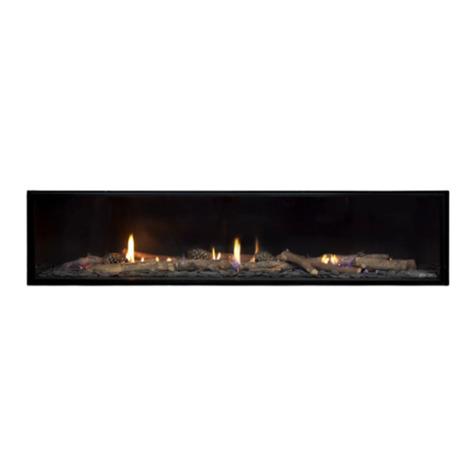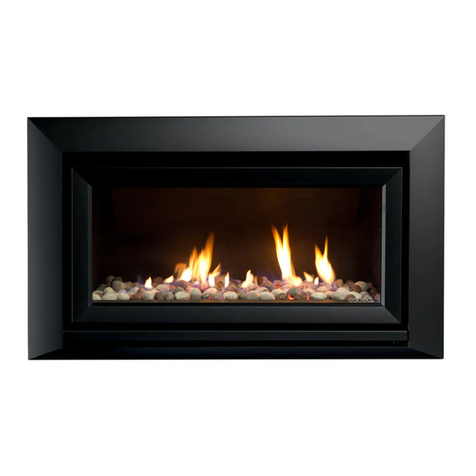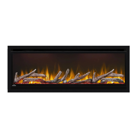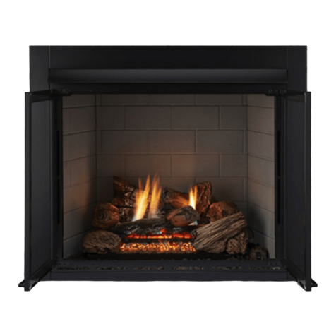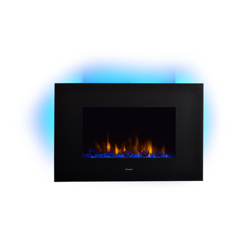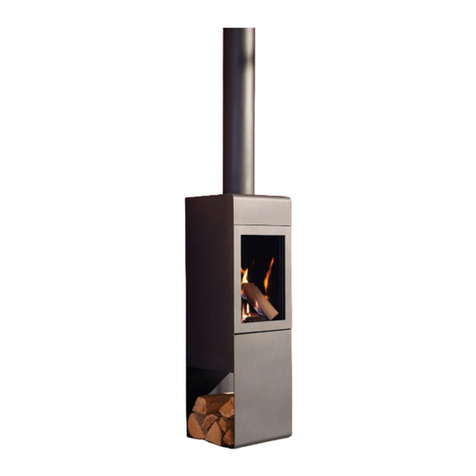
DN1150 Corner Gas Fireplace
Information Sheet for Builders and Architects
630704_3 DN1150 Corner Builders and Architects Informaon Sheet
3
14
wall framing
Fireplace glass
viewing area 30
wall lining
exposure line
only non-combustible or
heat resistant wall linings
allowed in shaded area
any wall lining or
finish in this area
For the full installaon manual and CAD
les, scan to visit the technical website
3
14
wall framing
Fireplace glass
viewing area 30
wall lining
exposure line
only non-combustible or
heat resistant wall linings
allowed in shaded area
any wall lining or
finish in this area
CAVITY OPTIONS
Please Note: the DN1150 Gas replace is non-load-bearing, make sure to provide
sucient support for any framework or building components above it.
The DN1150 Corner gas replace is versale for room installaon in dierent
conguraons. It ts beneath counters or cabinetry with a capped framework at
the minimum cavity height. The cavity can be made from various materials, both
combusble and non-combusble. Extra heat protecon might be necessary for
recessing or joinery specicaons.
NOTE: Available as an accessory, the Kitset Wall Unit (KWU) can assist in installaon
of the DN1150 Corner and Peninsula models. This metal support structure simplies
setup and can hold up to 500kg of framework and cladding without transferring load
to the replace.
FINISHES
Use 10mm to 20mm deep wall linings or nishes, taking care to select materials
suitable for the installaon. Prevent combusble or heat sensive wall linings from
extending forward or beneath the 14mm replace trim.
Maintain a 3mm gap (+/- 2mm) to the replace’s nishing trim.
Replace the 14mm replace trim with the 22mm Extended Trim Kit or a custom
soluon, for adequate heat protecon. Prolonged heat exposure may damage the
appearance or long-term performance of wall linings.
For specic nish details, refer to: www.escea.com/replace-specicaon
FIREPLACE BASE
Install the replace on a minimum 12mm rm, connuous surface like a concrete
oor, plywood, or compressed cement sheet. Avoid installing directly on carpet, rugs,
or heat-sensive oor nishes.
TV CLEARANCE
When mounng a TV or electrical appliance above a replace, this can be completed
surface-mounted or recessed. Ensure the TV’s base is at least 200mm above the glass
viewing area. Note that TV clearance recommendaons are suggesons only, and
Escea is not responsible for their compability with all electrical appliances.
Fireplace Width (A) including 14mm nishing trim 1288mm
Fireplace Height (B) 795mm
Fireplace Depth (C) excluding 14mm nishing trim 378mm
Framed Cavity Opening Width min. 1320mm
Framed Cavity Opening Height min. 850mm
Framed Cavity Opening Depth min. 365mm
FIREPLACE AND CAVITY DIMENSIONS
FURTHER INFORMATION
*This detail is applicable for all sides of the replace viewing area.
Where an installaon scenario is not covered within this document or the Escea
DN1150 Corner Install Manual, please contact the Escea Architectural Advisory Team
for further assistance.
PH (NZ): 0800 17 3000 PH (WA): 1800 730 140
FIREPLACE CLEARANCES
Ensure all clearances are met to any combusble or heat sensive materials in front,
above, to the side, or below the replace viewing area. Following these clearances,
will allow the use of standard building materials, whether combusble or non-
combusble.
Ensure that any combusble mantels or protruding ledges above the replace are
posioned at least 200mm above the viewing area. Mantel height depends on its
depth; the greater the protrusion, the higher the clearance. For more details, check
the Escea DN1150 Corner Install Manual at:
www.escea.com/replace-specicaons
A hearth is not necessary, but if used, a combusble hearth must be at least 100mm
below the glass viewing area or made enrely of non-combusble materials.
Install in accordance with AS/NZS5601.1 and the Escea DN1150 Corner Install
Manual. Contractors and installers should verify all dimensions on site prior to the
manufacture or construcon of any structure or nishes.
200mm
100mm
50mm
50mm
1000mm
1000mm
100mm
200mm
