Eskon EPA300 User manual
EPA300
USER
MANUAL
PROCESS CONTROL DEVICE

2
1. INDEX
1. INDEX ------------------------------------------------------------------------------------ 2
2. CONNECTIONS ------------------------------------------------------------------------- 3
3. FRONT PANEL DEFINITIONS------------------------------------------------------- 5
4. SETUP------------------------------------------------------------------------------------ 6
4.1 CONNECTION TO SENSOR DEVICE------------------------------------------------------------------ 6
4.2 DEVICE CALIBRATION---------------------------------------------------------------------------------- 7
4.3 ENTER RELAY SET VALUE ----------------------------------------------------------------------------- 8
5. OPERATING MODE: FUNCTIONS -------------------------------------------------10
5.1 Tare Function------------------------------------------------------------------------------------------ 10
5.2 Viewing the Maximum and Minimum Reading Values-------------------------------------- 10
5.3 Changing Quick Set Values------------------------------------------------------------------------- 10
5.4 Transition to Programming Mode---------------------------------------------------------------- 10
6. PROGRAMMING MODE: PROGRAMMING DIVICE ----------------------------12
6.1 Output Menu [OUT] --------------------------------------------------------------------------------- 12
6.1.1 1. Relay Output Setting (OUT-1)--------------------------------------------------------------- 12
6.1.2 2., 3., 4. Relay Output Settings (OUT-2-3-4)------------------------------------------------ 14
6.1.3 Current and Voltage Analog Output Settings (ANLOG)---------------------------------- 14
Wave Form (VAVE.F.)--------------------------------------------------------------------------------------- 14
Analog Output Scale Setting (Scale)-------------------------------------------------------------------- 14
6.1.4 UART and CANopen Digital Output Settings (DGTAL)------------------------------------ 15
6.1.5 Keypad Setting (SOUND) ------------------------------------------------------------------------ 15
6.2 Calibration Menu [CALIB] -------------------------------------------------------------------------- 15
6.2.1 Specifying Scale Values (SCALE) --------------------------------------------------------------- 15
6.2.2 Manual Calibration Method Determination (CALOP) ------------------------------------ 16
6.2.3 Number of Calibration (CL.CNT)--------------------------------------------------------------- 16
6.2.4 Automatic Calibration (START) ---------------------------------------------------------------- 16
6.3 Display Menu [DISP] --------------------------------------------------------------------------------- 16
6.3.1 Choice of decimal point location (POINT) --------------------------------------------------- 16
6.3.2 Tare Functain Settings (TARE) ----------------------------------------------------------------- 16
6.3.3 Screen Refresh Rate (REFRS) ------------------------------------------------------------------- 17
6.3.4 Blocking the on Screen Volatility (FILTR) ---------------------------------------------------- 18
6.4 Secure Menu [SECUR]------------------------------------------------------------------------------- 18
6.4.1 Hide Menu (HIDE)--------------------------------------------------------------------------------- 18
6.4.2 Menu Lock (LOCK)-------------------------------------------------------------------------------- 19
6.4.3 Set Password (PASS)------------------------------------------------------------------------------ 19
6.4.4 Return to Factory Setting (FTRY) -------------------------------------------------------------- 19
6.4.5 Restart the Device (RESET)---------------------------------------------------------------------- 19
7. WARRANTY DOCUMENT-----------------------------------------------------------21
3
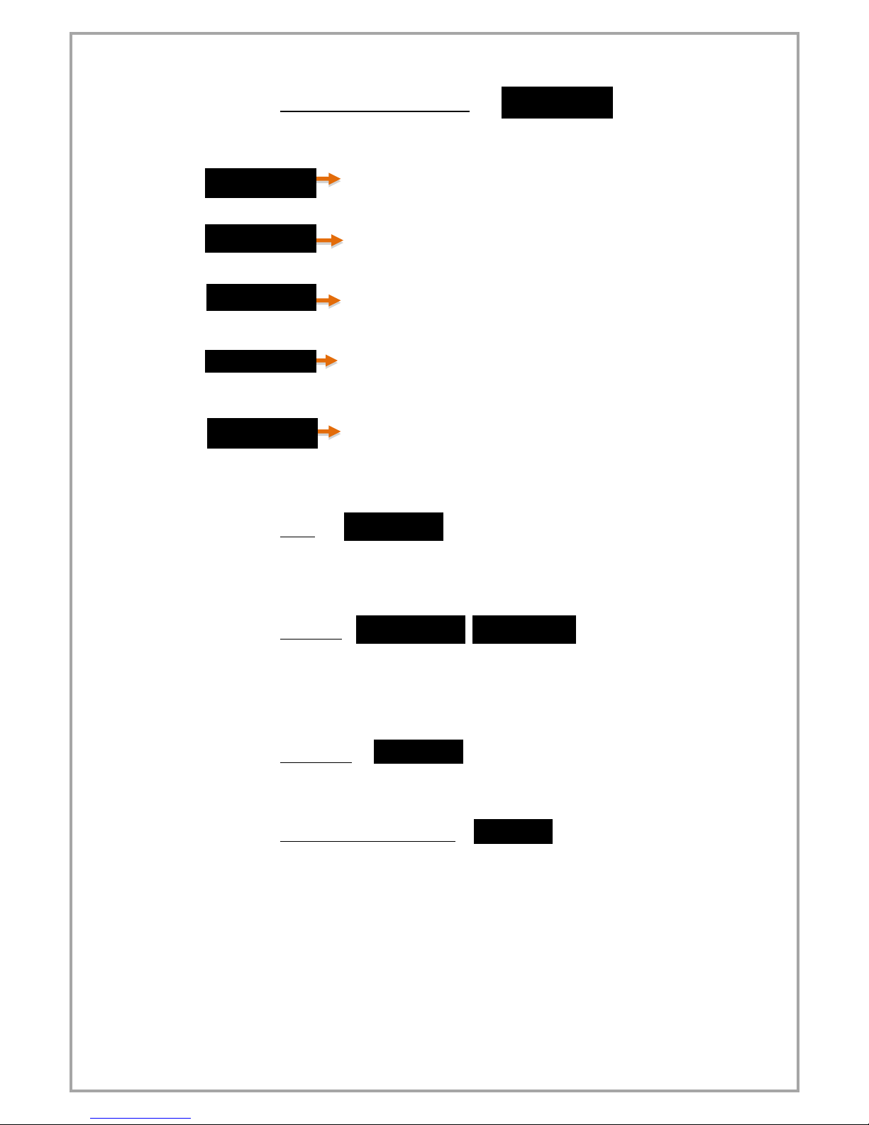
Supply Voltage
24 VAC / DC or 85 /
265 VAC
1. Relay Output
OUT-1
2. Relay Output
OUT-2
Shown in tables
below with pin
numbers assigned.
3. Relay Output
OUT-3
4. Relay Output
OUT-4
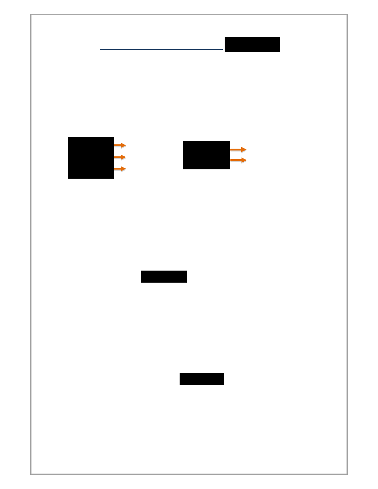
2. CONNECTIONS
Digital Comn.
28
29
30
RS485
A
B
GND
RS232
Rx
Tx
GND
USB HID
USB CONNECTOR
USB VIRTUAL
USB CONNECTOR
CANopen
CAN HIGH
CAN LOW
GND
Analog
Outputs
20
21
22
23
24
25
26
27
4-20 mA
Output
4-20 mA
Output
GND
4-20 mA
Output
GND
4-20 mA
Output
GND
0-10 V
Output
0-10 V
Output
GND
0-10 V
Output
GND
0-10 V
Output
GND
Tare
Output
Tare
Input
GND
COM
NO
NC
COM
NO
NC
COM
NO
NC
COM
NO
NC
L
N
1
2
3
4
5
6
7
8
9
10
11
12
13
14
+
15
16
17
18
19
20
21
22
23
24
25
26
27
28
29
30
-
+
-

4
SENSOR
15
16
17
18
19
Potentiometer
1. tip
2. tip
3. tip
X
X
4-20 mA Input
Supply
Sensor Signal
GND
X
X
0-10 V Input
Supply
Sensor Signal
GND
X
X
3,33 mV/V Input
Supply
X
GND
Signal(+)
Signal(-)
SAFETY WARNINGS
1. Follow the instructions and warnings in the user guide.
2. Please check the power supply type before connects energy to the device.
3. Please the device mounted on panel against dangers of fall, snap, shake
during working.
4. Make Sensor connections without energy on the device; do not connect in
any way during operation.
5. Make sure that is shielded cables between device and sensor.
6. Do not leave the device exposed to a heat source (solar, heater etc.)
7. EPA300 industrial control device is not suitable for use in the external
environment, Use only room conditions.
8. Wipe with a damp cloth to clean the device, do not use water, thinner etc.
9. Comply with the limit values specified in the technical specifications for
relay outputs.
10. The device cannot be changed by the user in the event of a fault, Please
contact our technical service in case of failure.
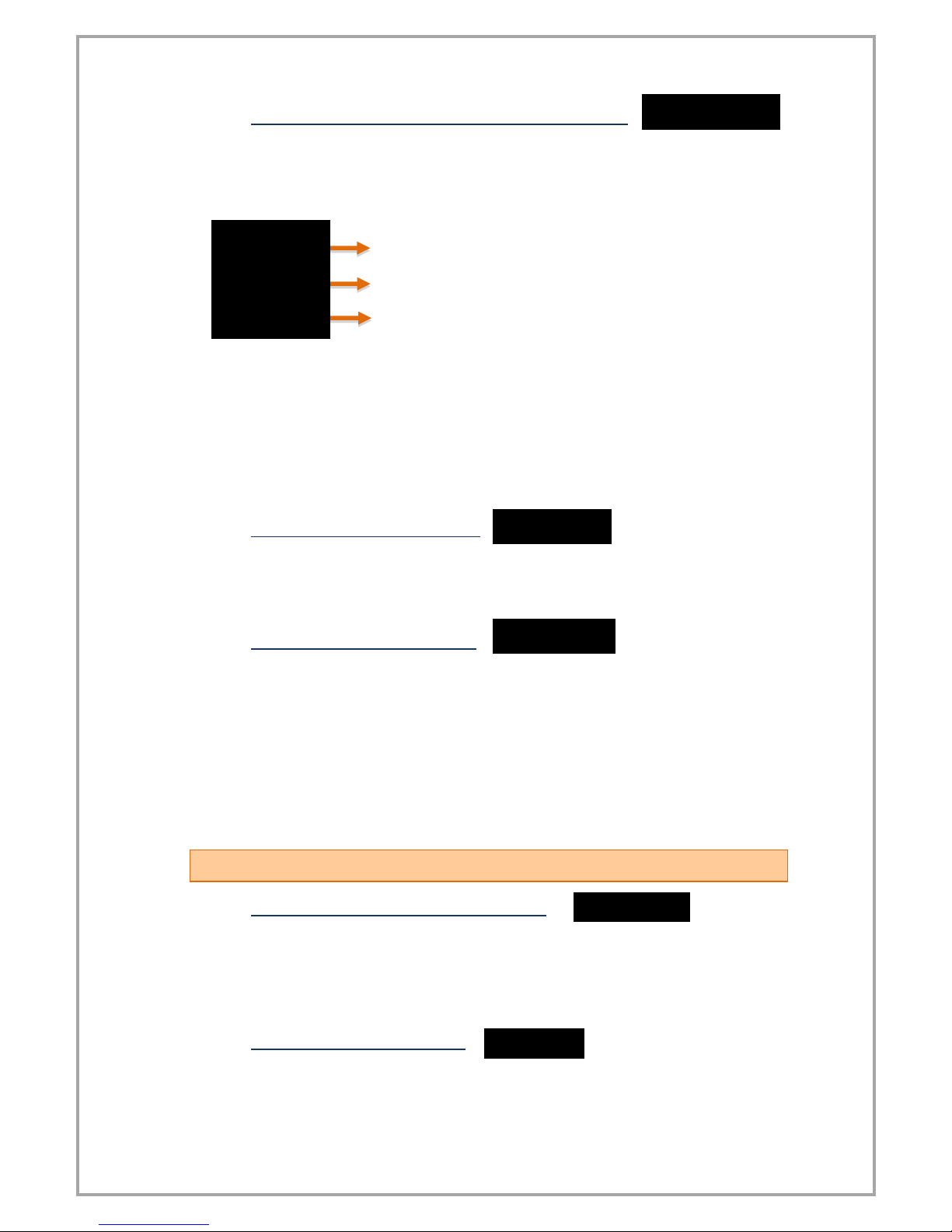
5
3. FRONT PANEL DEFINITIONS
8
7
1
2
3
4
6
5
1) PRG ( ): Programming and Enter key. It is used to enter the menus or
confirm the entered values.
2) ESC ( ): Escape, exit and backspace key. It is used to return to the upper
menu or to exit the menus.
3) UP ( ): Up key. Navigating between menus; Is used to increment the
value or move to a higher digit when entering a value.
4) DOWN ( ): Down key. Navigating between menus; Used to decrease the
value when entering a value or to switch to a lower step.
5)Set1 Status LED: 1. Display when the relay output is active.
6)Set2 Status LED: 2. Display when the relay output is active.
7)Set3 Status LED: 3. Display when the relay output is active.
8)Set4 Status LED: 4. Display when the relay output is active.
9)Min Status LED: Lights up when the lowest (minimum) value read from the
moment the device starts to operate.
10)Max Status LED: Lights up when the maximum read value is displayed
when the device starts operating.
11)Tare Status Led: Indicator that is lit when the key function is active.
12) Display Screen: Display screen consisting of 5 lines from a single line.
13) LED bar: The entered scale values increase and decrease in range.
9
10
00
00
00
00
00
11
12
13
6
4. SETUP
4.1 CONNECTION TO SENSOR DEVICE
Potentiometer connections:
Connections of 4-20mA or 0-10 V sensors:
Linear potentiometer
Pressure sensor with 4-20 mA
or 0-10 V output
+

7
3.33 mV / V Ratiometric Sensor connections:
4.2 DEVICE CALIBRATION
Your device is calibrated automatically according to factory settings and operates in
the 0-100 value range. That is, the smallest reading on the sensor shows 0 on the
screen and 100 on the screen. You can change this scale from the calibration menu.
Use S-LO for the minimum value that will be shown on the screen, S-HI for the
maximum value.
+
(Keep it pressed)
.
.
The decimal point
starts flashing. Use
the UP and DOWN
keys to select the
decimal point.
Press and hold the UP and DOWN
keys to move to the next step. To
enter a negative (-) value, press
the DOWN key to come to one of
the non-digitized steps.
When PRG key is
pressed and entered,
the value input screen
opens. Enter the
desired value using
the UP and DOWN
keys.
.
.
The new S-LO value you confirmed with the PRG key has been
set. Press UP to move to S-HI.
8
After specifying the S-LO value, you can do the same for the S-HI value.
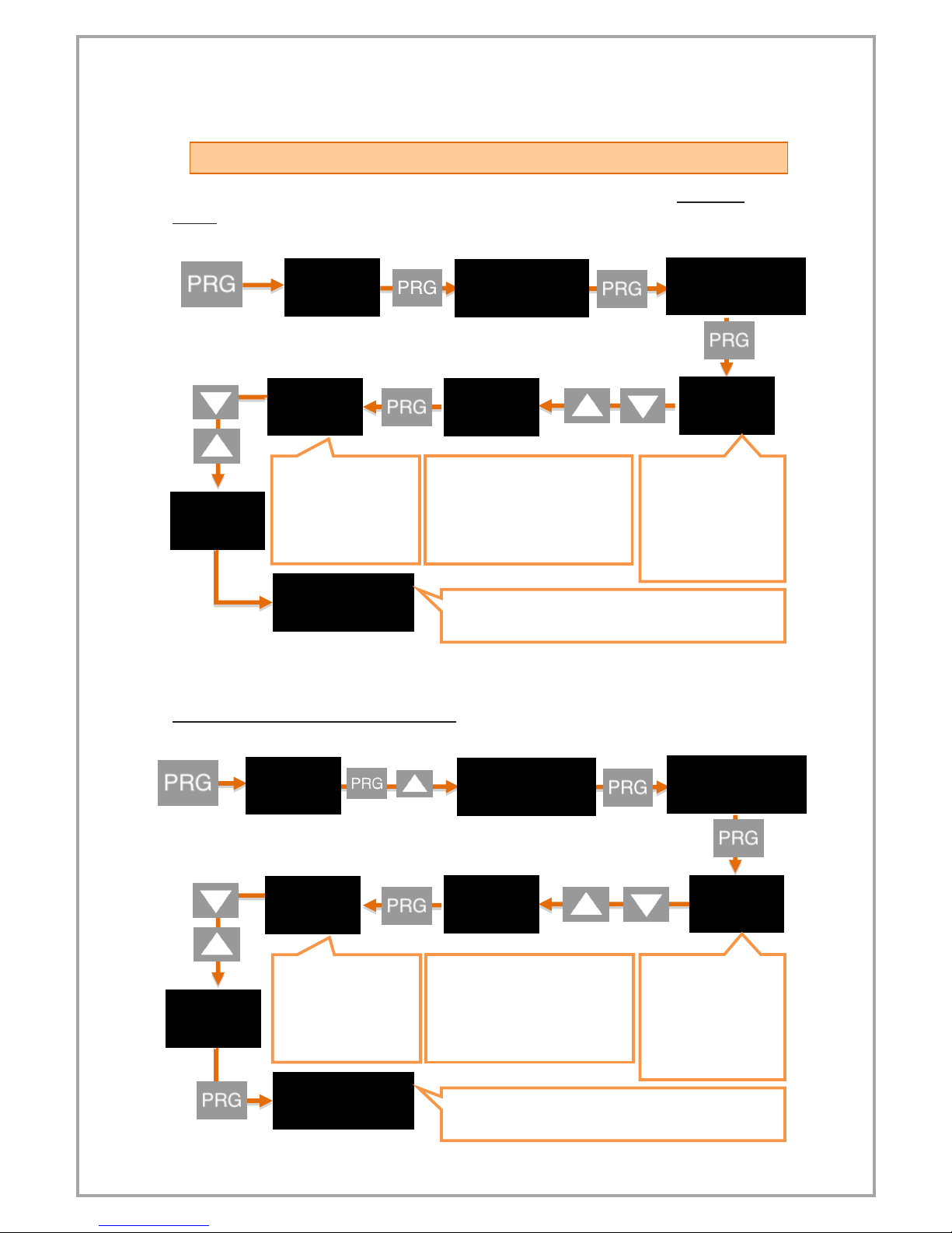
4.3 ENTER RELAY SET VALUE
Set the SET values for the relay outputs of your device to be activated. For SET-1
value:
2. Set the SET-2 value for Relay output:
(Keep it pressed)
.
The decimal point
starts flashing. Use the
UP and DOWN keys to
select the decimal
point.
Press and hold the UP and DOWN
keys to move to the next step. To
enter a negative (-) value, press
the DOWN key to come to one of
the non-digitized steps.
When PRG key is
pressed and entered,
the value input screen
opens. Enter the
desired value using
the UP and DOWN
keys.
.
The new S-LO value you confirmed with the PRG key has
been set. Press UP to move to S-HI.
.
(Keep it pressed)
.
When PRG key is
pressed and entered,
the value input screen
opens. Enter the
desired value using
the UP and DOWN
keys.
.
The new S-LO value you confirmed with the PRG key has
been set. Press UP to move to S-HI.
.
The decimal point
starts flashing. Use the
UP and DOWN keys to
select the decimal
point.
Press and hold the UP and DOWN
keys to move to the next step. To
enter a negative (-) value, press
the DOWN key to come to one of
the non-digitized steps.
9
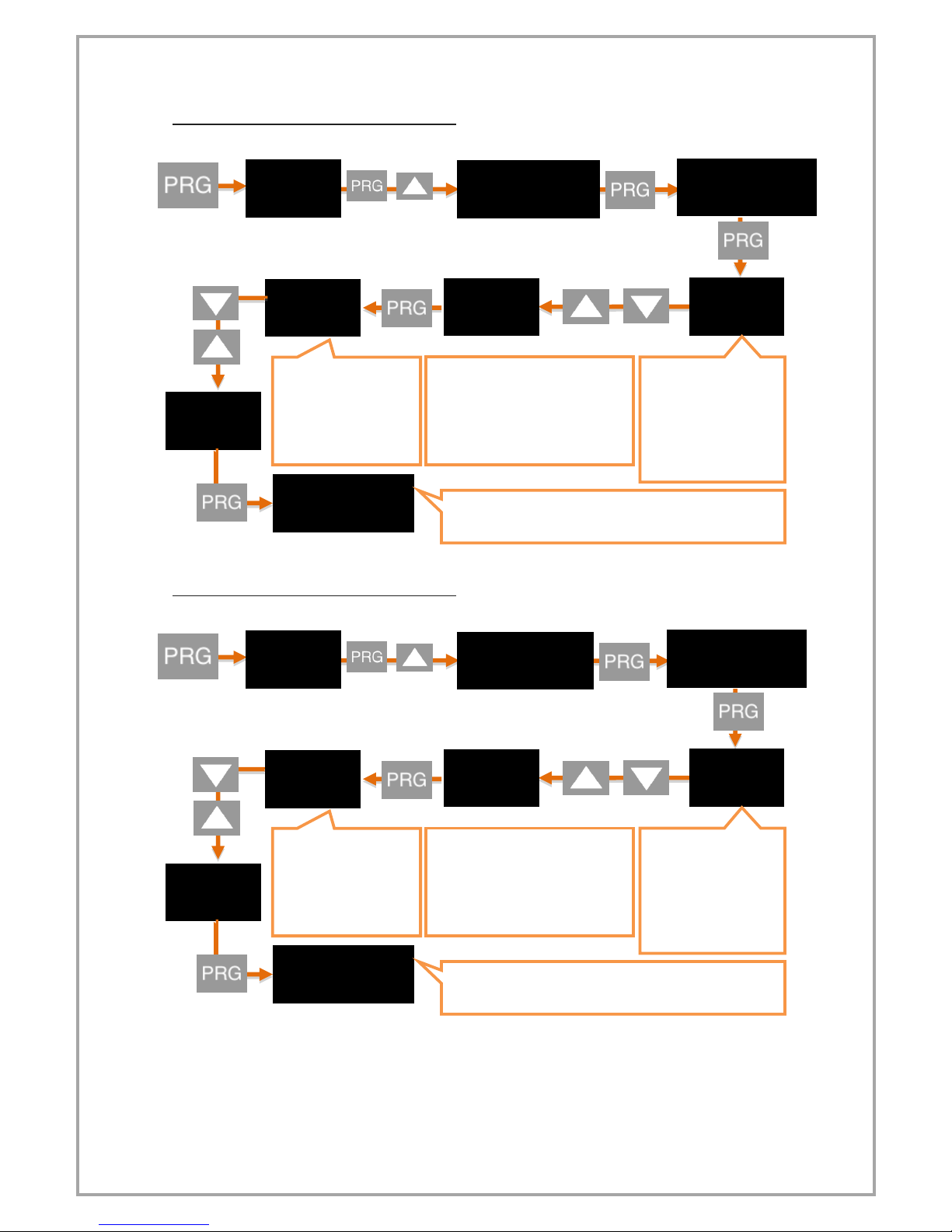
3. Set the SET-3 value for Relay output:
4. Set the SET-4 value for Relay output:
(Keep it pressed)
.
The decimal point
starts flashing. Use the
UP and DOWN keys to
select the decimal
point.
Press and hold the UP and DOWN
keys to move to the next step. To
enter a negative (-) value, press
the DOWN key to come to one of
the non-digitized steps.
When PRG key is
pressed and entered,
the value input screen
opens. Enter the
desired value using
the UP and DOWN
keys.
.
The new S-LO value you confirmed with the PRG key has
been set. Press UP to move to S-HI.
.
(Keep it pressed)
.
The decimal point
starts flashing. Use the
UP and DOWN keys to
select the decimal
point.
Press and hold the UP and DOWN
keys to move to the next step. To
enter a negative (-) value, press
the DOWN key to come to one of
the non-digitized steps.
When PRG key is
pressed and entered,
the value input screen
opens. Enter the
desired value using
the UP and DOWN
keys.
.
The new S-LO value you confirmed with the PRG key has
been set. Press UP to move to S-HI.
10
5. OPERATING MODE: FUNCTIONS
Your EPA300 process controller operates in two different modes. Your device is in
'operating mode' while the initial value of the sensor readout is displayed; In the
'programming mode' on the screen where the settings are changed and the parameters are
changed. In this section, the functions in operating mode are explained.
5.1 Tare Function
***Only works when the Tare function is active. For activating or explaining the types of functions,
6.3.2 Setting the Tare Function
Each time the UP key is pressed while the unit is in the operating mode, the Tare function is
activated according to the type of the selected function and the Tare status lights up.
5.2 Viewing the Maximum and Minimum Reading Values
If you press the DOWN key while the unit is in operating mode, you can see the lowest
(minimum) value read from the moment the unit starts to operate. At the same time, Min
status will flash on the screen.
When you press the DOWN key again, you can see the highest (maximum) value read from
the moment the device starts to operate. At the same time Max will be on the screen.
5.3 Changing Quick Set Values
Press and hold the ESC key to quickly change all adjustable setpoints while the unit is
in run mode. You can then change the desired SET value by pressing the PRG key. When
entering a value, press and hold the UP and DOWN keys to move to the next step. To enter a
negative (-) value, press the DOWN key to come to one of the non-digitized steps.
5.4 Transition to Programming Mode
To switch your device from working mode to programming mode
.
.
.
(Keep it pressed)
1
2
3
.
.
4
5
6

11
Press and hold PRG until OUT appears in the display. To return to the operating mode, press
the ESC key repeatedly until you return to the operating mode.
12
6. PROGRAMMING MODE: PROGRAMMING DIVICE
Your EPA300 process controller operates in two different modes. Your device is in
'operating mode' while the initial value of the sensor readout is displayed; In the
'programming mode' on the screen where the settings are changed and the parameters are
changed. In this section, the functions in Programming Mode are explained.
To switch your device from working mode to programming mode Press and hold
PRG until OUT appears in the display. To return to the operating mode, press the ESC key
repeatedly until you return to the operating mode. While your device is in Programming
Mode;
-To scroll between menus, press the DOWN and UP keys
-Press enter (PRG) to enter any menu.
-Use the ESC key to exit from any menu and return to the upper menu.
-When entering any parameter value, press the DOWN key to dicrease, press the UP
to increase the value. Press and hold the keys to move to the next or previous digit.
The EPA300 consists of 4 main menu items: Output, Secure, Display and Calibration.
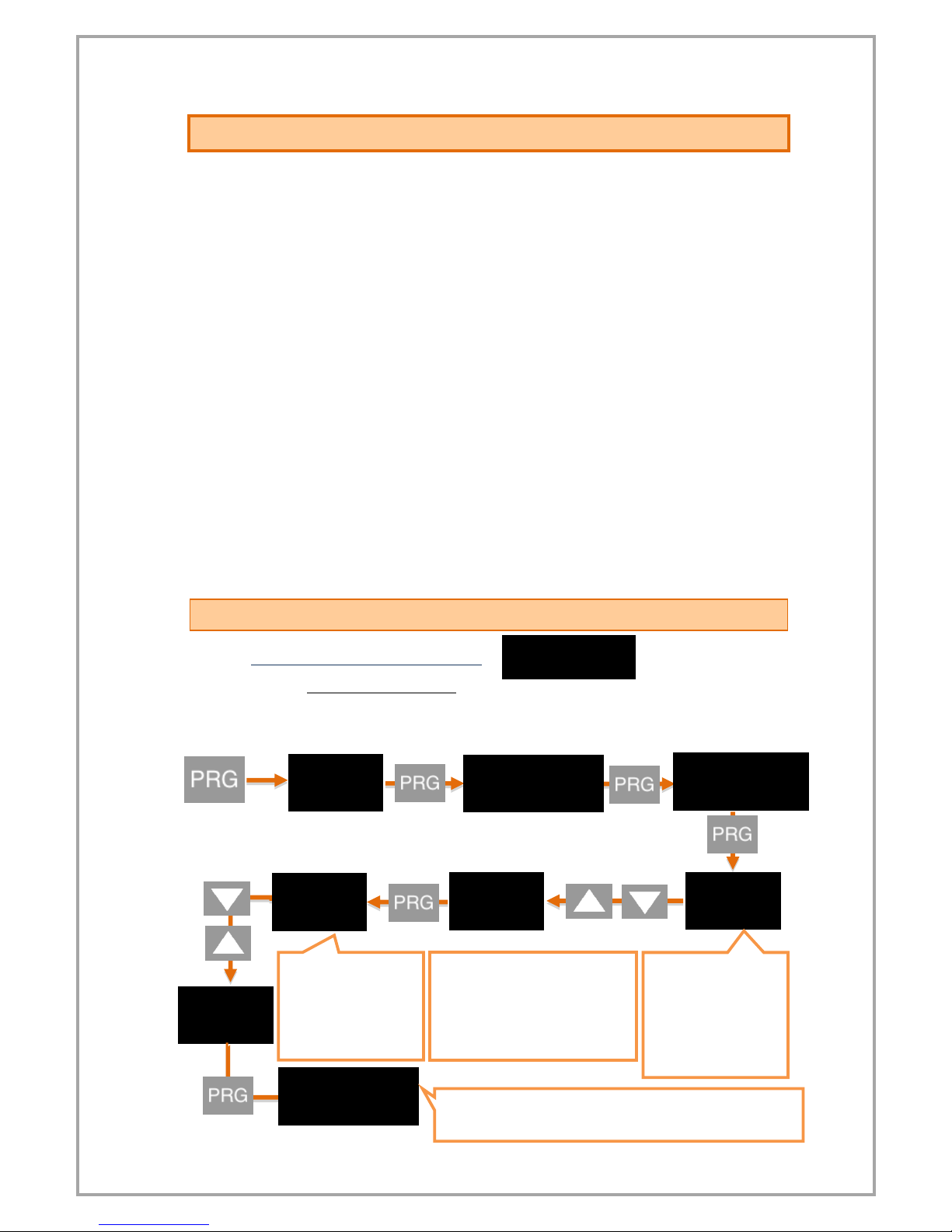
6.1 Output Menu [OUT]
6.1.1 1. Relay Output Setting (OUT-1)
6.1.1.1 Entering the Set Value
The first relay output activates and sets the value of the lit LED of the status SET1.
(Keep it pressed)
The decimal point
starts flashing. Use
the UP and DOWN
keys to select the
decimal point.
.
Press and hold the UP and DOWN
keys to move to the next step. To
enter a negative (-) value, press
the DOWN key to come to one of
the non-digitized steps.
When PRG key is
pressed and entered,
the value input screen
opens. Enter the
desired value using
the UP and DOWN
keys.
.
The new S-LO value you confirmed with the PRG key has been
set. Press UP to move to S-HI.
13
6.1.1.2 Relay Output Funtion Selection
This function selection determines when the relay output will be activated and
deactivated according to the set values.
6.1.1.3 Delay
It specifies in seconds how long the relay output will remain active after it is
activated. If '0' is entered as a zero value, the relay output will remain active until it
changes conditionally.
6.1.1.4 Hysteresis
Due to the unstability in decimal value read on the connected sensor, you can enter
the hysteresis value to prevent the relay from being turned on and off at any time,
so that the set value you set for the relay will be activated and deactivated as low as
Hysdn and above Hysup.
6.1.1.5 Offset value
If you want to add offset to the entered set value, this menu is used. If all set values
are selected forward or negative by the specified offset value, they are shifted back.
6.1.1.6 The default state of the relay
Depending on the factory settings of your device, the relay is normally closed and
activated with the specified setpoint and functions. Use the Cond option on the Out-
1 menu to activate the default in the default position and turn off with the specified
setpoint and functions. The factory setting NC (NormallyClosed) is the option that
the relay is normally closed, NO. (Normally Open) indicates that the relay is normally
open.
.
.
The relay is activated when the value read in the device
increases by increasing Set-1 value.
The relay is activated when the read value in the device is
between Set-1 and Set-2.
The value read in the device is activated whenever the
set-1 value increases or decreases.
The value read in the device activates the relay whenever
the Set-1 or Set-2 value increases or decreases.
The value read in the device is activated when the value
of Set-1 or the value of Set-1 is increased or decreased by
every level such as 2,3,4,5 ....
14
6.1.2 2., 3., 4. Relay Output Settings (OUT-2-3-4)
In this menu you can set the relay outputs 2, 3 and 4 of your EPA300. Complete
settings 5.1.1. The 1 st relay output described in chapter is the same as the OUT-1
settings.
6.1.3 Current and Voltage Analog Output Settings (ANLOG)
If your EPA300, which is manufactured specifically for your order, has an analog
output module, you can make the necessary settings from this menu.
Select the analogue output from the TYPE menu:
From the COND menu, select whether the analogue output module is active or not.
Use ON to activate or OFF to activate.
From InvrS menu, you can choose which value to increase or decrease according to
the sensor reading on the analogue output. This option, which is OFF by default,
provides an analog output that increases or decreases in proportion to the value
read at the sensor. If you turn this ON, the value read out at the sensor will increase
while the value at the analog output will decrease, ie an inversely proportional
output will be provided.
Wave Form (VAVE.F.)
The waveform of the output signal can be selected from the Vave.f menu. There are
4 options in the menu: Liner, Sin, Cos, Trian. When the liner option is confirmed with
the PRG key, a linearly increasing waveform is obtained in the specified scale range.
When the Cos option is confirmed with the PRG key, a waveform in the form of a
waveform that starts from zero and completes a complete cosine wave is obtained
at the scale interval specified. When the Sin option is confirmed, a waveform in the
form of a waveform that starts at the peak value of the sine wave and completes a
complete sinusoidal wave in the determined scale range is obtained. When the
triangle option is selected in the same way, a triangle wave is obtained in the scale
interval determined at the exact middle value corresponding to the top.
Analog Output Scale Setting (Scale)
In the device with the analogue output feature, SCALE mode in this menu must be
ON to set the output signal to the desired scale range. S-LO started appearing on the
analogue menu afterwards. And S-HI. Options and scale values can be entered.
0.5 - 4.5 Volt
0 –20 mA
0 - 10 Volt
4 - 20 mA
0 - 5 Volt
.
.
.
.
.
15
6.1.4 UART and CANopen Digital Output Settings (DGTAL)
WARNING: After changing the UART or CANopen settings, you need to restart the
device for the changes to take effect.
If your device has a USB port, use MyPanelMeter, which you can download from our
website to check your device. Check the user manual of the program.
6.1.4.1. UART Settings
If you are communicating with your device via RS-485 or RS-232; You can make the
necessary settings here. You can select the communication protocol, baudrate,
parity, address and period information. For the MODBUS Protocol address
information, see the relevant booklet.
6.1.4.2. CANopen Ayarları
Here you can configure the baud rate, Node ID, Heartbeat, PDO etc. of your device
related to the CANopen protocol.
For more information on CANopen, see the EPA300-CANopen booklet.
6.1.5 Keypad Setting (SOUND)
When you press any key on your device, you can turn the beep sound on and off from this
menu. Use ON to turn the sound on, OFF to turn it off.
6.2 Calibration Menu [CALIB]
6.2.1 Specifying Scale Values (SCALE)
When your device is calibrated to its factory settings, it operates at a value range
of 0-100. That is, the smallest reading on the sensor shows 0 on the screen and 100
on the screen. You can change this scale from this menu.
Use the S-LO for the minimum value of the scale, and the S-HI menus for the
maximum value. To change the value, press the PRG key. After specifying the value
with the UP and DOWN keys, press the PRG key again to locate the decimal point.
Then press the PRG key to confirm the value.
You can use the Fctor menu to expand this scale by multiplying it by a fixed
factor. The number of this factor, which is the default value of 1, is multiplied by the
values of S-LO and S-HI to determine the scale value.
For example; When you set the S-LO value to 1, the S-HI value to 20 and make
the factor 4, your device will run in the 4-80 value range.
WARNING: Changing the scale value does not change the calibration of your
device, it only indicates the displayed value range on the screen. For the calibration
of the instrument, 6.2.2.
16
6.2.2 Manual Calibration Method Determination (CALOP)
Your device has been automatically calibrated during production. If you do not, you
can do this calibration according to the sensor. You need to select the calibration
method from this menu.
In the 2-point calibration option, only the maximum and minimum points are
selected. With the multiple calibration option, you can calibrate your device at up to
10 different points. For example; If the length of the sensor is 40 cm and you want to
calibrate at 5 different points, these points are; There must be 0 cm, 10 cm, 20 cm,
30 cm, and 40 cm points at which the sensor starts.
Select the FCAL option if you want to calibrate your device to factory calibration
again.
6.2.3 Number of Calibration (CL.CNT)
In this menu that appears when you select the segmented calibration option, you
can specify the number of points you want to calibrate the device. It's a maximum of
10.
6.2.4 Automatic Calibration (START)
From this menu 5.2.2. You can start your automatic calibration by pressing the PRG
key according to the selected calibration method in the section. During the
calibration that will start according to your chosen meta; You can see the calibration
point to be determined on the first line by the ignored segment number and on the
second line the unprocessed value read on the sensor. You can scroll through the
segments, ie the calibration points, with the UP and DOWN keys. You can confirm
the segment you want to specify with the PRG key while the sensor is in position for
calibration. DONE will appear on the screen for a very short period of time.
6.3 Display Menu [DISP]
6.3.1 Choice of decimal point location (POINT)
In the value that appears on the display in run mode, you can set the position of the
decimal point in this menu. This value, which is '2' in the factory settings, indicates
how many decimal places to display after a call. If you select '0', only the whole
number appears on the screen.
6.3.2 Tare Functain Settings (TARE)
In this menu you can define the Tare Function and its properties.
From the EVENT menu you can select the Tare Function type:
.
.
Factory calibration (Default)
2 point calibration
Segmented calibration
.
.
.

17
When the unit is in operation mode, each time the UP key is pressed;
In the PrSet option, you can specify the value to be equalized when the Tare key is
pressed.
If your EPA300, which is specially manufactured according to your order, has the
Digital Tare Input module, you can make settings from the INPUT menu under the
Tare menu.
The EDGE option determines which edge of the edge signal coming from the Tare
function is activated. RISE for rising edge, FALL for falling edge. For example; When
you connect this signal to a button, the RISE option activates the tare when the
button is pressed and the FALL option when the button is released after the button
is pressed.
In the FILTR option, you can specify how many milliseconds the modulated signal is
to be controlled. By default, this value is 100 ms.
6.3.3 Screen Refresh Rate (REFRS)
Indicates how many milliseconds the value displayed on the screen will be refreshed.
By default this value is 100 ms; To reduce or reduce the on-screen vibrations, or
reduce the duration of your device's response to movement of the sensor.
ZERO: Then the value read on the sensor is equal to zero and the
Tare state LED is lit.
PRESET: Then, the value read on the sensor is equalized to the
specified value and the Tare status LED is lit.
REPEATED ZERO: The first time it is pressed, the value read on the
sensor is equal to zero and the Tare status LED is lit. When it is
pressed later, the read value returns to the state before the key is
activated and the Tare status LED is turned off.
REPEATED PRESET: When pressed for the first time, the value read
on the sensor is equal to zero and the Tare status LED is lit. When
it is pressed later, the read value returns to the state before the
key is activated and the Tare status LED is turned off.
.
.

18
6.3.4 Blocking the on Screen Volatility (FILTR)
Your EPA300 is programmed to display the signals received from its connected
sensor in the most accurate way on the screen by processing them with special
algorithms. But; You can solve this problem by filtering from this menu in the event
of a trembling of the value displayed on the screen due to various reasons such as
noise in the vicinity, disturbances in the sensor. There are three different filtering
methods for this:
1. AVRGE (Average Calculation):
When you activate this filter by turning the STATE option ON, your device will
refresh the value that appears on the display after you have read as many values
from the sensor as you would select COUNT. For example; COUNT will default to
500, and your device will refresh the value on the screen after you have taken 500
samples from the sensor, that is, after reading it, taking the average of these values.
Accordingly, increasing COUNT will reduce flicker on the screen; But your device will
slow the response of the sensor to its rapid movement.
2. LQE(Lineer Quadratic Estimation):
You can also activate this filter, also known as a thick filter, by turning the STATE
option ON. If you decrease the default COVARIANCE of 500, the flicker on the screen
will decrease; But your device will slow down the reaction of the sensor to its rapid
movement.
3. HYS (hysteresis):
You can activate the hysteresis filter by turning the STATE option ON. With this filter,
which has two parameters named Delta and A.Error, the value read from the sensor
is not reflected on the screen until it changes to Delta. When the sum of the non-
reflected values on the screen is equal to A.Error, the display is updated with the
average of these values.
6.4 Secure Menu [SECUR]
6.4.1 Hide Menu (HIDE)
You can hide the menus ON you do not want the operator to see your device to use
them.
All menus except Secure are hidden.
The Output menu is hidden.
The Calib menu is hidden.
The Display menu is hidden.
The Quick Set change menu is hidden. See. 5.3.
.
.
.
.
.

19
6.4.2 Menu Lock (LOCK)
If you have not set a password before, you will see NPASS in the display when you
enter this menu. Press the PRG key to set the desired password here. Then use the
DOWN and UP keys to select the menus you want to lock. Definitions of Menüler
5.4.1. It is the same as in the Menu Hiding section.
6.4.3 Set Password (PASS)
Use this menu item to set a password or to change the password you have
previously set. If no password was previously set; When you enter this menu, the
display will show NPASS. Press the PRG key to set the desired password here. If the
password has already been set; The display shows PASS? Will appear and you will be
asked to enter this password. After inputting the password, the display will show
NPASS. You can specify your new password here and confirm it with the PRG key.
6.4.4 Return to Factory Setting (FTRY)
You can return your EPA300 to factory settings from the time box you desire. Press
the PRG key to return to the factory settings. Here you are going to face the PASS?
You need to enter 12345, which is the factory password, not the user password you
specified on the password screen.
6.4.5 Restart the Device (RESET)
In any case, press the PRG key to come back to this menu to restart your device. The
device will automatically power off and on and start working.
NOTE: The EPA 300 can be used with the instrument panel only, without the need
for relay outputs.
.
20
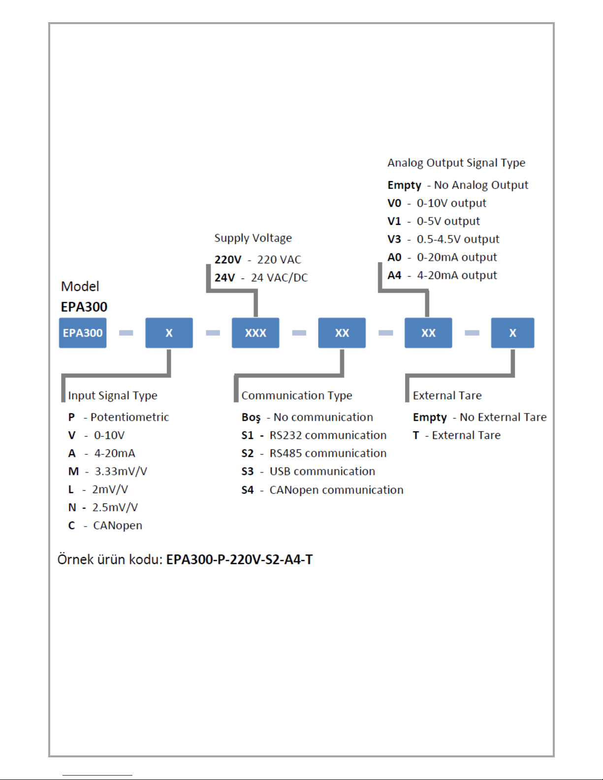
Order Coding:
When ordering your EPA 300 process controller, you can use the following coding format.
Other manuals for EPA300
1
Table of contents
Other Eskon Controllers manuals


